EP0904876A2 - Chuck - Google Patents
Chuck Download PDFInfo
- Publication number
- EP0904876A2 EP0904876A2 EP98116954A EP98116954A EP0904876A2 EP 0904876 A2 EP0904876 A2 EP 0904876A2 EP 98116954 A EP98116954 A EP 98116954A EP 98116954 A EP98116954 A EP 98116954A EP 0904876 A2 EP0904876 A2 EP 0904876A2
- Authority
- EP
- European Patent Office
- Prior art keywords
- chuck
- rotary cylinder
- end portion
- portion side
- cylinder
- Prior art date
- Legal status (The legal status is an assumption and is not a legal conclusion. Google has not performed a legal analysis and makes no representation as to the accuracy of the status listed.)
- Granted
Links
Images

Classifications
-
- B—PERFORMING OPERATIONS; TRANSPORTING
- B23—MACHINE TOOLS; METAL-WORKING NOT OTHERWISE PROVIDED FOR
- B23B—TURNING; BORING
- B23B31/00—Chucks; Expansion mandrels; Adaptations thereof for remote control
- B23B31/02—Chucks
- B23B31/10—Chucks characterised by the retaining or gripping devices or their immediate operating means
- B23B31/117—Retention by friction only, e.g. using springs, resilient sleeves, tapers
Definitions
- the present invention relates generally to a chuck gripping a tool of a drill, end mill and so forth. More particularly, the invention relates to a chuck, in which a chuck cylinder having an outer periphery tapered toward a tip end side of a chuck body, is projected, a flange portion is formed on the base end side of the chuck cylinder, a tightening rotary cylinder having a tapered inner peripheral surface is externally fitted on the chuck cylinder, and a plurality of needle rollers causing orbital motion in spiral fashion are disposed between the tightening rotary cylinder and the chuck cylinder.
- Fig. 3 shows the conventional chuck.
- the chuck is designed to insert a base end portion of a tool (not shown) into a chuck cylinder 2 of a chuck body 1, and the tightening rotary cylinder 4 externally fitted on the tapered outer peripheral surface of the chuck cylinder 2 via the needle rollers 3 is rotated in a direction approaching to the flange portion 5 of the chuck body 1 to contract a diameter of the chuck cylinder 2 to firmly grip and fasten the tool.
- the conventional chuck is constructed to leave a proper length of gap S between a base end surface 4a of the tightening rotary cylinder 4 and a tip end surface 5a of the flange portion 5 on the side of the chuck body in a condition where the tool is sufficiently gripped and fixed.
- the present invention has been worked out to solve the problem set forth above. It is an object of the present invention to increase rigidity of a chuck including extremely shortening an under head length.
- Another object of the present invention is to make an under head length of the chuck shorter than the under head length of the conventional chuck.
- a further object of the present invention is to provide increased contact area when the rear end surface of the tightening rotary cylinder abuts with the tip end surface of the flange portion to increase rigidity of the chuck, to avoid interference between the tip end portion of the tightening rotary cylinder with the surrounding and to facilitate production.
- a chuck comprises:
- An axial length of the flange portion of the chuck body may be shorter than a dimension defined in a dimension defined by Japanese industrial standard.
- a ratio of the outer diameter D1 of the larger diameter end portion side of the tightening rotary cylinder and the outer diameter of the smaller diameter end portion side may be within a range of about 0.75 to about 0.85.
- a ratio (L1/L2) of an axial length L1 of the larger diameter end portion side and an axial length L2 of the smaller diameter end portion side may be within a range of about 0.60 to about 0.85.
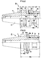
- a chuck body 10 includes a taper shank portion 11 fitted on a main shaft (not shown) of a machining center or so forth, a flange portion 12 formed on a large diameter side end portion of the taper shank portion 11 and a chuck cylinder 13 integrally projected coaxially from the flange portion 12 to the tip end side of the chuck body 10.
- the chuck cylinder 13 has a straight inner peripheral surface 13a corresponding to a straight shank portion (not shown) of the tool to be gripped and fixed, and a tapered outer peripheral surface 13b reducing diameter toward a tip end.
- a groove form cut-out 14 for good resilient deformation.
- a tightening rotary cylinder 15 has a diameter on a rear end portion side 15 1 than that on a front end portion side 15 2 .
- An external diameter D1 of the rear end surface 15a of the rotary cylinder 15 is formed to be slightly smaller than an external diameter Df of the flange portion 12 of the chuck body 10. It should be noted that the external diameter D1 of the rear end surface 15a of the tightening rotary cylinder may be formed the same as the external diameter Df of the flange portion 12.
- a ratio between the larger diameter end side, namely the external diameter D1 of the rear end portion side 15 1 and the small diameter end side, namely the external diameter D2 of the tip end portion side 15 2 is in a range of about 0.75 to about 0.85. Also, it is preferred that a ratio (L1/L2) of a length L1 of the rear end portion side 15 1 in the axial direction and a length L2 of the tip end portion side 15 2 is in a range of about 0.60 to about 0.85.
- the tightening rotary cylinder 15 has a tapered inner peripheral surface 15b tapered to reduce diameter toward the tip end corresponding to the tapered outer peripheral surface 13a of the chuck cylinder 13.
- a plurality of needle rollers 16 which causes orbital motion in spiral fashion with respect to the tapered outer peripheral surface 13a of the chuck cylinder 13, is disposed.
- the needle roller 16 is held in a retainer 17. With respect to a generating line of the outer peripheral surface 13a of the chuck cylinder 13, an axis of each needle roller 16 is arranged with an appropriate inclination.
- the needle roller 16 causes orbital motion in spiral direction with rotation with respect to the tapered outer peripheral surface 13a of the chuck cylinder 13 to ride on the tapered outer peripheral surface 13a.
- the chuck cylinder 13 reduces the diameter resiliently to grip and fix the tool.
- the tightening rotary cylinder 15 contacts the rear end surface 15a thereof with the tip end surface 12a of the flange portion 12 in a condition where the chuck cylinder 13 reduces a diameter via the needle roller 16 by rotation in the tightening direction to sufficiently grip and fix the tool.
- the rear end surface 15a of the rotary cylinder 15 contacts with the tip end surface 12a of the flange portion 12 by rotating the tightening rotary cylinder 15 in the tightening direction to reduce diameter of the chuck cylinder 13 via the needle rollers 16 to sufficiently grip and fix the tool.
- the rear end surface 15a of the tightening rotary shaft 15 of the shown embodiment of the chuck A according to the invention contacts with the tip end surface 12a of the flange portion 12 to eliminate the gap.
- the under head length Na of the chuck A becomes shorter than the under head length Nc of the conventional chuck C in the corresponding amount to increase the rigidity of the chuck.
- the rear end portion side 15 1 of the tightening rotary cylinder 15 is formed with a diameter larger than the tip end portion side 15 2 , and in conjunction therewith, the outer diameter D1 of the rear end surface is the same as the outer diameter Df of the flange portion 12 of the chuck body 10 or slightly smaller.
- the rear end surface 15a of the tightening rotary cylinder 15 contacts with the tip end surface 12a of the flange portion 12 to provide extremely large contact area to further increase rigidity of the chuck.
- the reason why the tightening rotary cylinder 15 is formed to have a ratio (D2/D1) of the outer diameter D1 of the larger diameter end portion side 15 1 and the smaller diameter end portion side 15 2 within a range of about 0.75 to about 0.85, is that the outer diameter D1 of the rear end surface 15a of the rotary cylinder 15 is substantially equal to the outer diameter Df of the flange portion 12 of the chuck body 10, and that if the diameter on the tip end portion side 15 2 is excessively small, rigidity and strength of the rotary cylinder 15 per se is lowered, and if the diameter of the tip end portion side 15 2 is excessively large, a problem should be encountered to cause interference with the surrounding.
- D2/D1 In order to avoid lowering of rigidity of the tightening rotary cylinder 15 per se , D2/D1 has to be greater than or equal to about 0.75. On the other hand, in order to avoid a problem in interference, D2/D1 has to be less than or equal to about 0.85.
- Fig 2 shows another embodiment of a chuck B according to the present invention.
- the chuck B is characterized in that the length H of a flange portion 22 of the chuck body 10 in the axial direction is formed to be shorter than a dimension Ho defined in Japanese industrial standard (see Fig. 3).
- the shown embodiment has the same construction as the chuck A shown in Fig. 1, except for the foregoing point.
- the tightening rotary cylinder 15 is tightened for contacting the rear end surface 15a with the end surface of the flange portion 12.
- the diameter of the rear end portion side 15 1 is greater than that of the tip end portion side 15 2
- the outer diameter D1 of the rear end surface 15a is the same as the outer diameter Df of the flange portion 12 of the chuck body 10 or slightly smaller than the latter
- a ratio (D2/D1) between the outer diameter D1 of the rear end portion side 15 1 and the outer diameter D2 of the tip end portion side 15 2 is in a range of about 0.75 to about 0.85
- a ratio (L1/L2) between the axial length L1 of the rear end portion side 15 1 and the axial length L2 of the tip end portion side 15 2 is in a range of about 0.60 to about 0.85.
- the under head length Nb of the chuck B can be further shortened than the under head length Na of the chuck A shown in Fig. 1 for the corresponding length to further enhance the rigidity of the chuck.
- a gripping groove G for manipulator is provided in the outer peripheral surface of the flange portion 22, so that an engaging portion of the manipulator may engage with the groove G upon griping operation of the chuck body 10 by the manipulator.
- the outer peripheral portion t on one side of the gripping groove G is required to form at least a given width of the outer peripheral surface to permit the supporting roller to slidingly contact. It should be noted that, by the shown embodiment of the present invention, since the axial length of the flange portion of the chuck body is formed to be shorter than the dimension defined by Japanese industrial standard in the predetermined length, the under head length of the chuck can be shorted in the corresponding amount to further enhance rigidity of the chuck.
Landscapes
- Engineering & Computer Science (AREA)
- Mechanical Engineering (AREA)
- Gripping On Spindles (AREA)
- Clamps And Clips (AREA)
Abstract
Description
It should be noted that, by the shown embodiment of the present invention, since the axial length of the flange portion of the chuck body is formed to be shorter than the dimension defined by Japanese industrial standard in the predetermined length, the under head length of the chuck can be shorted in the corresponding amount to further enhance rigidity of the chuck.
Claims (5)
- A chuck comprising:a chuck cylinder projected on a tip end side of a chuck body having a tapered outer peripheral surface;a tightening rotary cylinder having a tapered inner peripheral surface and externally fitted on said chuck cylinder;a plurality of needle rollers causing orbital motion in spiral fashion and disposed between said tightening rotary cylinder and said chuck cylinder;a rear end portion side of said tightening rotary cylinder being provided greater diameter than that on a tie end portion side,an outer diameter on a read end surface of said tightening rotary cylinder being formed to be slightly smaller than or equal to an outer diameter of a flange portion of said chuck body, andsaid tightening rotary cylinder being tightened to abut said rear end surface with an end surface of said flange portion.
- A chuck as set forth in claim 1, wherein an axial length of said flange portion of said chuck body is shorter than a dimension defined in a dimension defined by Japanese industrial standard.
- A chuck as set forth in claim 1, wherein a ratio of the outer diameter D1 of said larger diameter end portion side of said tightening rotary cylinder and the outer diameter of said smaller diameter end portion side is within a range of about 0.75 to about 0.85.
- A chuck as set forth in claim 2, wherein a ratio (D2/D1) of the outer diameter D1 of said larger diameter end portion side of said tightening rotary cylinder and the outer diameter of said smaller diameter end portion side is within a range of about 0.75 to about 0.85.
- A chuck as set forth in claim 1, wherein a ratio (L1/L2) of an axial length L1 of said larger diameter end portion side and an axial length L2 of said smaller diameter end portion side is within a range of about 0.60 to about 0.85.
Applications Claiming Priority (3)
| Application Number | Priority Date | Filing Date | Title |
|---|---|---|---|
| JP26134497 | 1997-09-26 | ||
| JP26134497A JP3390640B2 (en) | 1997-09-26 | 1997-09-26 | Chuck |
| JP261344/97 | 1997-09-26 |
Publications (3)
| Publication Number | Publication Date |
|---|---|
| EP0904876A2 true EP0904876A2 (en) | 1999-03-31 |
| EP0904876A3 EP0904876A3 (en) | 1999-04-07 |
| EP0904876B1 EP0904876B1 (en) | 2004-07-21 |
Family
ID=17360539
Family Applications (1)
| Application Number | Title | Priority Date | Filing Date |
|---|---|---|---|
| EP19980116954 Expired - Lifetime EP0904876B1 (en) | 1997-09-26 | 1998-09-08 | Chuck |
Country Status (3)
| Country | Link |
|---|---|
| EP (1) | EP0904876B1 (en) |
| JP (1) | JP3390640B2 (en) |
| DE (1) | DE69825108T2 (en) |
Family Cites Families (5)
| Publication number | Priority date | Publication date | Assignee | Title |
|---|---|---|---|---|
| GB2162098B (en) * | 1984-06-29 | 1987-10-07 | Daishowa Seiki | Chuck assembly |
| US4721423A (en) * | 1986-10-07 | 1988-01-26 | Daishowa Seiki Kabushiki Kaisha | Chuck |
| DE4209175A1 (en) * | 1992-03-20 | 1993-09-23 | Imt Ingenieurgemeinschaft Fuer | CHUCK |
| JP3563562B2 (en) * | 1997-02-24 | 2004-09-08 | 株式会社日研工作所 | Chuck |
| JP3040905U (en) | 1997-02-25 | 1997-09-05 | 株式会社日研工作所 | Chuck |
-
1997
- 1997-09-26 JP JP26134497A patent/JP3390640B2/en not_active Expired - Lifetime
-
1998
- 1998-09-08 EP EP19980116954 patent/EP0904876B1/en not_active Expired - Lifetime
- 1998-09-08 DE DE69825108T patent/DE69825108T2/en not_active Expired - Lifetime
Also Published As
| Publication number | Publication date |
|---|---|
| EP0904876A3 (en) | 1999-04-07 |
| EP0904876B1 (en) | 2004-07-21 |
| DE69825108T2 (en) | 2005-07-21 |
| JPH1199406A (en) | 1999-04-13 |
| JP3390640B2 (en) | 2003-03-24 |
| DE69825108D1 (en) | 2004-08-26 |
Similar Documents
| Publication | Publication Date | Title |
|---|---|---|
| US5421682A (en) | Tool bit chucking shank | |
| JPH06134608A (en) | Tool attaching device | |
| AU6296998A (en) | Screw | |
| US6022029A (en) | Chuck assembly | |
| EP0904876B1 (en) | Chuck | |
| JPS58211802A (en) | Bore groove machining tool | |
| US5743123A (en) | Method of thread rolling a screw shaft | |
| JP3513681B2 (en) | Holding tool | |
| JPS6257807A (en) | Drill | |
| JPH0735693Y2 (en) | Machine tool spindle | |
| USH885H (en) | Bearing device for a crankshaft | |
| JP2000000705A (en) | Tool chuck | |
| JPH0410963Y2 (en) | ||
| JP2579452Y2 (en) | Drill | |
| JPS64241Y2 (en) | ||
| JPS5848003Y2 (en) | Check | |
| JPH081763Y2 (en) | Chuck | |
| JP2601429Y2 (en) | Shank type rotary cutting tool | |
| KR200206749Y1 (en) | Super precision lathe | |
| JP2887657B2 (en) | Manufacturing method of collet chuck | |
| JPH0540886Y2 (en) | ||
| KR0178477B1 (en) | Tool for Chamfering Automotive Bearings | |
| KR19980058887A (en) | Boring Method of Workpiece | |
| JPH1158246A (en) | Lapping reamer | |
| KR200206731Y1 (en) | Chuck correcting jig |
Legal Events
| Date | Code | Title | Description |
|---|---|---|---|
| PUAI | Public reference made under article 153(3) epc to a published international application that has entered the european phase |
Free format text: ORIGINAL CODE: 0009012 |
|
| PUAL | Search report despatched |
Free format text: ORIGINAL CODE: 0009013 |
|
| AK | Designated contracting states |
Kind code of ref document: A2 Designated state(s): CH DE FR GB IT LI |
|
| AX | Request for extension of the european patent |
Free format text: AL;LT;LV;MK;RO;SI |
|
| AK | Designated contracting states |
Kind code of ref document: A3 Designated state(s): AT BE CH CY DE DK ES FI FR GB GR IE IT LI LU MC NL PT SE |
|
| AX | Request for extension of the european patent |
Free format text: AL;LT;LV;MK;RO;SI |
|
| 17P | Request for examination filed |
Effective date: 19990520 |
|
| AKX | Designation fees paid |
Free format text: CH DE FR GB IT LI |
|
| 17Q | First examination report despatched |
Effective date: 20000405 |
|
| GRAP | Despatch of communication of intention to grant a patent |
Free format text: ORIGINAL CODE: EPIDOSNIGR1 |
|
| GRAS | Grant fee paid |
Free format text: ORIGINAL CODE: EPIDOSNIGR3 |
|
| GRAA | (expected) grant |
Free format text: ORIGINAL CODE: 0009210 |
|
| AK | Designated contracting states |
Kind code of ref document: B1 Designated state(s): CH DE FR GB IT LI |
|
| REG | Reference to a national code |
Ref country code: GB Ref legal event code: FG4D |
|
| REG | Reference to a national code |
Ref country code: CH Ref legal event code: EP |
|
| REF | Corresponds to: |
Ref document number: 69825108 Country of ref document: DE Date of ref document: 20040826 Kind code of ref document: P |
|
| REG | Reference to a national code |
Ref country code: CH Ref legal event code: NV Representative=s name: NOVAGRAAF INTERNATIONAL SA |
|
| ET | Fr: translation filed | ||
| PLBE | No opposition filed within time limit |
Free format text: ORIGINAL CODE: 0009261 |
|
| STAA | Information on the status of an ep patent application or granted ep patent |
Free format text: STATUS: NO OPPOSITION FILED WITHIN TIME LIMIT |
|
| 26N | No opposition filed |
Effective date: 20050422 |
|
| PG25 | Lapsed in a contracting state [announced via postgrant information from national office to epo] |
Ref country code: IT Free format text: LAPSE BECAUSE OF NON-PAYMENT OF DUE FEES Effective date: 20050908 |
|
| PGRI | Patent reinstated in contracting state [announced from national office to epo] |
Ref country code: IT Effective date: 20091201 |
|
| REG | Reference to a national code |
Ref country code: CH Ref legal event code: PFA Owner name: DAISHOWA SEIKI CO., LTD. Free format text: DAISHOWA SEIKI CO., LTD.#3-39, NISHIISHIKIRI-CHO 3-CHOME#HIGASHIOSAKA-SHI, OSAKA 579-8013 (JP) -TRANSFER TO- DAISHOWA SEIKI CO., LTD.#3-39, NISHIISHIKIRI-CHO 3-CHOME#HIGASHIOSAKA-SHI, OSAKA 579-8013 (JP) |
|
| REG | Reference to a national code |
Ref country code: FR Ref legal event code: PLFP Year of fee payment: 18 |
|
| REG | Reference to a national code |
Ref country code: FR Ref legal event code: PLFP Year of fee payment: 19 |
|
| REG | Reference to a national code |
Ref country code: FR Ref legal event code: PLFP Year of fee payment: 20 |
|
| PGFP | Annual fee paid to national office [announced via postgrant information from national office to epo] |
Ref country code: DE Payment date: 20170928 Year of fee payment: 20 Ref country code: FR Payment date: 20170928 Year of fee payment: 20 Ref country code: GB Payment date: 20170921 Year of fee payment: 20 Ref country code: IT Payment date: 20170926 Year of fee payment: 20 Ref country code: CH Payment date: 20170921 Year of fee payment: 20 |
|
| REG | Reference to a national code |
Ref country code: DE Ref legal event code: R071 Ref document number: 69825108 Country of ref document: DE |
|
| REG | Reference to a national code |
Ref country code: CH Ref legal event code: PL |
|
| REG | Reference to a national code |
Ref country code: GB Ref legal event code: PE20 Expiry date: 20180907 |
|
| PG25 | Lapsed in a contracting state [announced via postgrant information from national office to epo] |
Ref country code: GB Free format text: LAPSE BECAUSE OF EXPIRATION OF PROTECTION Effective date: 20180907 |