EP0904867A2 - Method and system for determining heating point and heating line in bending of steel plate - Google Patents
Method and system for determining heating point and heating line in bending of steel plate Download PDFInfo
- Publication number
- EP0904867A2 EP0904867A2 EP98118299A EP98118299A EP0904867A2 EP 0904867 A2 EP0904867 A2 EP 0904867A2 EP 98118299 A EP98118299 A EP 98118299A EP 98118299 A EP98118299 A EP 98118299A EP 0904867 A2 EP0904867 A2 EP 0904867A2
- Authority
- EP
- European Patent Office
- Prior art keywords
- steel plate
- heating
- points
- point
- line
- Prior art date
- Legal status (The legal status is an assumption and is not a legal conclusion. Google has not performed a legal analysis and makes no representation as to the accuracy of the status listed.)
- Granted
Links
Images


Classifications
-
- B—PERFORMING OPERATIONS; TRANSPORTING
- B21—MECHANICAL METAL-WORKING WITHOUT ESSENTIALLY REMOVING MATERIAL; PUNCHING METAL
- B21D—WORKING OR PROCESSING OF SHEET METAL OR METAL TUBES, RODS OR PROFILES WITHOUT ESSENTIALLY REMOVING MATERIAL; PUNCHING METAL
- B21D11/00—Bending not restricted to forms of material mentioned in only one of groups B21D5/00, B21D7/00, B21D9/00; Bending not provided for in groups B21D5/00 - B21D9/00; Twisting
- B21D11/20—Bending sheet metal, not otherwise provided for
-
- B—PERFORMING OPERATIONS; TRANSPORTING
- B21—MECHANICAL METAL-WORKING WITHOUT ESSENTIALLY REMOVING MATERIAL; PUNCHING METAL
- B21D—WORKING OR PROCESSING OF SHEET METAL OR METAL TUBES, RODS OR PROFILES WITHOUT ESSENTIALLY REMOVING MATERIAL; PUNCHING METAL
- B21D11/00—Bending not restricted to forms of material mentioned in only one of groups B21D5/00, B21D7/00, B21D9/00; Bending not provided for in groups B21D5/00 - B21D9/00; Twisting
- B21D11/22—Auxiliary equipment, e.g. positioning devices
Definitions
- This invention relates to a method and a system for determining a heating point and a heating line in the bending of a steel plate. More specifically, the invention relates to the method and system useful for application to the bending of a steel plate having complicated curved surfaces, such as an outer panel of a ship hull.
- the outer panel of a ship hull is composed of a steel plate about 10 to 30 mm thick with a complicated undevelopable curved surface which reduces propulsion resistance for efficient navigation in the water.
- a processing method generally called line heating has been known for long. This method heats the surface of a steel plate locally by means of a gas burner or the like, to cause the extraplane angular deformation or intraplane shrinkage deformation of the steel plate due to plastic distortion, and skillfully combines these deformations to obtain the desired shape. This method is used at many shipyards.
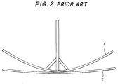
- an operator compares the shapes of each wooden pattern 1 and the steel plate 2 by visual observation, and considers differences between their shapes, e.g., the clearance between the wooden pattern 1 and the steel plate 2. Based on this consideration, the operator studies what position to heat in order to bring the steel plate 2 close to the target shape. As a result, the operator determines each heating position (heating point). Concretely, the wooden pattern 1 is rolled along the frame line of the steel plate 2 in a vertical plane (the same plane as in Fig. 2). The points of contact of the wooden pattern 1 with the steel plate 2 during the rolling motion are watched to determine the heating points in consideration of the clearance between the wooden pattern 1 and the steel plate 2 in each state.
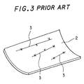
- the steel plate 2 is heated with a gas burner by the operator along the heating lines 3 determined by the operator's sense based on many years of experience. As a result, a predetermined curved surface is obtained. Acquiring the ability to determine the heating lines 3 rationally is said to require more than about 5 years of experience. This has posed the problems of the aging and shortage of experienced technicians. The bending procedure also takes a large amount of time for incidental operations, such as the production, mounting and removal of the wooden pattern 1 for the steel plate 2, thus lengthening the entire operating time.
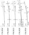
- the wooden pattern 1' is rolled along a frame line from the initial position shown in Fig. 6(a), whereby the wooden pattern 1' is brought into contact with the steel plate 2' as shown in Fig. 6(b). At this time, contact points on the steel plate 2' are designated as A, B, while contact points on the wooden pattern 1' are designated as C, D. Then, the wooden pattern 1' is rolled in the reverse direction to return it to the initial state (the state shown in Fig. 6(a)) as shown in Fig. 6(c).
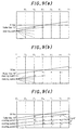
- FIG. 9(b) shows that the heating points belonging to Group 1 based on the starting point 1 have been fixed, and the heating points based on the starting point 2 are being investigated. On this occasion, the heating points that have already been grouped are neither used as the starting points nor subjected to grouping. In this manner, the heating points lying below the roller line 16'' are grouped.
- a straight line (or a curve) is obtained from the sequence of heating points in each group, as shown in Fig. 9(c), and this line is designated as a virtual heating line 3'.
- the heating line 3' is obtained by the method of least squares if it is a straight line, or by spline interpolation or the like if it is a curve.
- the target shape is rolled along the steel plate, but the same effect is obtained if the steel plate is rolled along the target shape. In short, one of them may be rolled relative to the other so that the contact point of the two is obtained.
- the purpose of determining the heating points in the above manner is to obtain the heating positions and heating intensities (quantities of heat given to the steel plate) for causing the necessary change in shape. Between the heating intensity and the angle ⁇ , there is a predetermined relationship, which can be found experimentally. Thus, at a time when the angle ⁇ is found, the heating intensity can be determined (needles to say, if the angle ⁇ is recorded as data, it can be converted to the heating intensity later, where necessary). Thus, at step S 14 , the heating intensity with respect to the angle ⁇ may be obtained along with data on the angle ⁇ , although this is not directly related to the processing for finding the heating point.
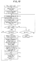
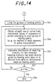
- Fig. 14 shows an example in which the heating intensity (determined by the bending angle ⁇ ) at each heating point is taken into consideration during the processings illustrated in Fig. 13, and the information on the heating intensity is incorporated into the information on the heating line.
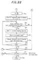
- the distribution of the heating intensity is calculated for the determined heating line by the process subsequent to step S 56 in accordance with the instant embodiment (step S 59 ).
- the heating intensity has been directly obtained separately based on the bending angle ⁇ at the heating point, or is determined on the basis of information on the bending angle ⁇ at the heating point.
- the heating points on each heating line 3 can be heated with the most appropriate quantity of heat.
- this can be easily achieved by controlling an electric current supplied to the high frequency heating coil to control the amount of heat input to the steel plate 2.
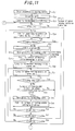
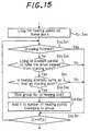
- Fig. 15 shows an example in which the heating intensity (determined by the bending angle ⁇ ) at each heating point is taken into consideration during the processings illustrated in Figs. 11 and 12, and this heating intensity is also incorporated into the conditions for grouping.
- the heating intensity is same as the heating intensity at the starting point (the heating intensity includes that within a predetermined tolerance range) (step S 60 ). If this judgment shows that the heating point in question does not have the same heating intensity, this heating point is excluded from the relevant group. In other words, the same group No. as that of the starting point is assigned to the heating point, provided that it has the same heating intensity.
- the heating points on each heating line 3 can be heated with the same quantity of heat.
- the most appropriate amount of heat input to the steel plate can be given by keeping the electric current supplied to the high frequency heating coil constant for a single heating line 3.
- the term "virtual" has been defined as not existing as a real one, but existing as electronic data or a graphic expressed in a visible form on the display unit 16. However, such a restriction need not be applied to the technical idea of the present invention.
- a wooden pattern and a steel plate which an operator prepares by plotting are also included in the concept "virtual” as referred to herein, unless they are real ones.
- Figs. 16 to 18 are explanation drawings for illustrating another example of processing performed by the heating point determining unit 41.
- the processing shown in these drawings focuses on the fact that the curved shape of the steel plate 2 on a predetermined line, such as each frame line, can be regarded as a collection of arcs with a plurality of curvatures.
- the arc of the target shape is compared with the arc of an actually measured shape corresponding to this arc portion on the basis of the curvatures of both arcs. Based on the results of comparison, the heating point is determined. This method is called “the curvature comparison method".
- the target shape is divided into a plurality of fine segments D 1 to D n , these fine segments D 1 to D n are regarded as arcs, curvatures or radii are designated for the respective segments D 1 to D n , and the lengths l 1 to l n of the arcs of the respective segments D 1 to D n are designated, whereby the target shape can be specified.
- the target shape data 12 in the respective segments D 1 to D n are compared with the steel plate measurement data 13, the amount of deformation of the steel plate 2 for making the target shape and the shape of the steel plate agree can be determined by the difference between the two types of data.
- the deformation in heat bending is bending at the heating points. That is, the arcs in the respective fine segments are approximated by straight lines.
- the bending angle at this time is designated as ⁇
- the bending angle ⁇ is given as the difference between the angle formed by the adjacent sublines of the fold line N o and the angle formed by the adjacent sublines of the fold line N C .
- l 0 l C
- the amount of heating e.g., the amount of heat input based on parameters such as an electric current, and the clearance between a high frequency heating coil and the steel plate 2, during high frequency heating
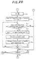
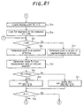
- the heating point determining unit 11 prepares the following data on the basis of the target shape data 12 read in: 1 ⁇ position data on the reference line on each frame line, 2 ⁇ position data on the end of the steel plate 2 as the object to be processed, 3 ⁇ curvature data on the arc in each segment when the curved shape of the steel plate 2 on each frame line is regarded as a collection of arcs with a plurality of curvatures, and 4 ⁇ position data on the point of the boundary between each segment and the adjacent segment.
- the curvature data 3 ⁇ are values designated at the time of designing, or if these values are not designated, the data are calculated using the point sequence data of the target shape data 12.
- data corresponding to 1 ⁇ to 4 ⁇ are compiled from the steel plate shape measurement data 13 as well. At this time, the data 3 ⁇ correspond to the respective segments of the target shape.
- the heating point determining unit 11 processes the data 1 ⁇ to 4 ⁇ on the target shape and the measured shape, and calculates the heating points by the curvature comparison method described based on Figs. 16 to 18.
- An example of the relevant concrete procedure will be explained by reference to Figs. 19 to 22.
- Figs. 19 to 22 are flow charts showing this example.
- the heating points are obtained on the frame lines, but needless to say, the way of obtaining them is not restricted to this manner.
- the frame lines are lines corresponding to the positions at which frame materials are attached.
- data on their positions are stored as design data.
- the use of the frame lines in obtaining the heating points is advantageous in the applicability of such data.
Landscapes
- Engineering & Computer Science (AREA)
- Mechanical Engineering (AREA)
- Length Measuring Devices With Unspecified Measuring Means (AREA)
- Bending Of Plates, Rods, And Pipes (AREA)
- Investigating Strength Of Materials By Application Of Mechanical Stress (AREA)
Abstract
Description
Claims (28)
- A method for determining a heating point in the bending of a steel plate, comprising:placing a virtual wooden pattern formed from target shape data on a virtual steel plate formed from steel plate shape measurement data, said target shape data being data on a target shape of the steel plate to be bent, and said steel plate shape measurement data being obtained by measuring a surface shape of the steel plate;rolling the wooden pattern or the steel plate along a specific line on the steel plate, such as a frame line, from a predetermined reference position in a plane including a cross section of the steel plate, to bring the wooden pattern and the steel plate into contact at two points, with the contact points on the steel plate being designated as A, B, and the contact points on the wooden pattern being designated as C, D;then rolling the wooden pattern or the steel plate in the reverse direction to return it to the reference position;with the wooden pattern or the steel plate being returned to the reference position, obtaining a straight line U connecting the contact points A, B and a straight line V connecting the contact points C, D; anddetermining a heating point on the basis of a point of intersection of the straight lines U, V.
- A method for determining a heating point in the bending of a steel plate, comprising:placing a virtual wooden pattern formed from target shape data on a virtual steel plate formed from steel plate shape measurement data, said target shape data being data on a target shape of the steel plate to be bent, and said steel plate shape measurement data being obtained by measuring a surface shape of the steel plate;rolling the wooden pattern or the steel plate along a specific line on the steel plate, such as a frame line, from a predetermined reference position in a plane including a cross section of the steel plate, to bring the wooden pattern and the steel plate into contact at two points, with the contact points on the steel plate being designated as A, B, and the contact points on the wooden pattern being designated as C, D;then rolling the wooden pattern or the steel plate in the reverse direction to return it to the reference position;with the wooden pattern or the steel plate being returned to the reference position, obtaining a straight line U connecting the contact points A, B and a straight line V connecting the contact points C, D; anddetermining a heating point on the basis of a point of intersection of the straight lines U, V, and also determining a bending angle for the steel plate at the heating point on the basis of an angle of intersection of the straight lines U, V.
- A method for determining a heating point in the bending of a steel plate, comprising:placing a virtual wooden pattern formed from target shape data on a virtual steel plate formed from steel plate shape measurement data, said target shape data being data on a target shape of the steel plate to be bent, and said steel plate shape measurement data being obtained by measuring a surface shape of the steel plate;rolling the wooden pattern or the steel plate along a specific line on the steel plate, such as a frame line, from a predetermined reference position in a plane including a cross section of the steel plate, to bring the wooden pattern and the steel plate into contact at two points, with the contact points on the steel plate being designated as A, B, and the contact points on the wooden pattern being designated as C, D;then rolling the wooden pattern or the steel plate in the reverse direction to return it to the reference position;with the wooden pattern or the steel plate being returned to the reference position, obtaining a straight line U connecting the contact points A, B and a straight line V connecting the contact points C, D; anddetermining a heating point on the basis of a point of intersection of the straight lines U, V; whereinafter obtaining a heating point, or a heating point and a bending angle, relative to a certain reference point, the same steps as described above are repeated while bringing the contact points A, C on a reference point side, which have been used in the determination of the heating point, into contact with each other to use their contact point as a new reference point, thereby determining respective heating points, or respective heating points and respective bending angles, along a specific line up to the end of the steel plate.
- A method for determining a heating point in the bending of a steel plate, comprising:placing a virtual wooden pattern formed from target shape data on a virtual steel plate formed from steel plate shape measurement data, said target shape data being data on a target shape of the steel plate to be bent, and said steel plate shape measurement data being obtained by measuring a surface shape of the steel plate;rolling the wooden pattern or the steel plate along a specific line on the steel plate, such as a frame line, from a predetermined reference position in a plane including a cross section of the steel plate, to bring the wooden pattern and the steel plate into contact at two points, with the contact points on the steel plate being designated as A, B, and the contact points on the wooden pattern being designated as C, D;then rolling the wooden pattern or the steel plate in the reverse direction to return it to the reference position;with the wooden pattern or the steel plate being returned to the reference position, obtaining a straight line U connecting the contact points A, B and a straight line V connecting the contact points C, D; anddetermining a heating point on the basis of a point of intersection of the straight lines U, V, and also determining a bending angle for the steel plate at the heating point on the basis of an angle of intersection of the straight lines U, V; whereinafter obtaining a heating point, or a heating point and a bending angle, relative to a certain reference point, the same steps as described above are repeated while bringing the contact points A, C on a reference point side, which have been used in the determination of the heating point, into contact with each other to use their contact point as a new reference point, thereby determining respective heating points, or respective heating points and respective bending angles, along a specific line up to the end of the steel plate.
- A method for determining a heating line in the bending of a steel plate, comprising:placing a virtual wooden pattern formed from target shape data on a virtual steel plate formed from steel plate shape measurement data, said target shape data being data on a target shape of the steel plate to be bent, and said steel plate shape measurement data being obtained by measuring a surface shape of the steel plate;rolling the wooden pattern or the steel plate along a specific line on the steel plate, such as a frame line, from a predetermined reference position in a plane including a cross section of the steel plate, to bring the wooden pattern and the steel plate into contact at two points, with the contact points on the steel plate being designated as A, B, and the contact points on the wooden pattern being designated as C, D;then rolling the wooden pattern or the steel plate in the reverse direction to return it to the reference position;with the wooden pattern or the steel plate being returned to the reference position, obtaining a straight line U connecting the contact points A, B and a straight line V connecting the contact points C, D;determining a heating point on the basis of a point of intersection of the straight lines U, V;after obtaining a heating point, or a heating point and a bending angle, relative to a certain reference point, repeating the same steps as described above while bringing the contact points A, C on a reference point side, which have been used in the determination of the heating point, into contact with each other to use their contact point as a new reference point, thereby determining respective heating points, or respective heating points and respective bending angles, along a specific line up to the end of the steel plate;drawing straight lines from a certain heating point on a certain line, as a starting point, to heating points on other lines on the basis of the heating points that have been so determined;examining the degree of parallelism between each of the straight lines and a roller line involved during primary bending of the steel plate;if the degree of parallelism is within a predetermined range, performing grouping of the relevant heating points as the heating points of the same group; andconnecting the respective heating points of the same group by a straight line or a curve to determine a heating line.
- A method for determining a heating line in the bending of a steel plate, comprising:placing a virtual wooden pattern formed from target shape data on a virtual steel plate formed from steel plate shape measurement data, said target shape data being data on a target shape of the steel plate to be bent, and said steel plate shape measurement data being obtained by measuring a surface shape of the steel plate;rolling the wooden pattern or the steel plate along a specific line on the steel plate, such as a frame line, from a predetermined reference position in a plane including a cross section of the steel plate, to bring the wooden pattern and the steel plate into contact at two points, with the contact points on the steel plate being designated as A, B, and the contact points on the wooden pattern being designated as C, D;then rolling the wooden pattern or the steel plate in the reverse direction to return it to the reference position;with the wooden pattern or the steel plate being returned to the reference position, obtaining a straight line U connecting the contact points A, B and a straight line V connecting the contact points C, D;determining a heating point on the basis of a point of intersection of the straight lines U, V, and also determining a bending angle for the steel plate at the heating point on the basis of an angle of intersection of the straight lines U, V;after obtaining a heating point, or a heating point and a bending angle, relative to a certain reference point, repeating the same steps as described above while bringing the contact points A, C on a reference point side, which have been used in the determination of the heating point, into contact with each other to use their contact point as a new reference point, thereby determining respective heating points, or respective heating points and respective bending angles, along a specific line up to the end of the steel plate;drawing straight lines from a certain heating point on a certain line, as a starting point, to heating points on other lines on the basis of the heating points that have been so determined;examining the degree of parallelism between each of the straight lines and a roller line involved during primary bending of the steel plate;if the degree of parallelism is within a predetermined range, performing grouping of the relevant heating points as the heating points of the same group; andconnecting the respective heating points of the same group by a straight line or a curve to determine a heating line.
- A method for determining a heating line in the bending of a steel plate, comprising:placing a virtual wooden pattern formed from target shape data on a virtual steel plate formed from steel plate shape measurement data, said target shape data being data on a target shape of the steel plate to be bent, and said steel plate shape measurement data being obtained by measuring a surface shape of the steel plate;rolling the wooden pattern or the steel plate along a specific line on the steel plate, such as a frame line, from a predetermined reference position in a plane including a cross section of the steel plate, to bring the wooden pattern and the steel plate into contact at two points, with the contact points on the steel plate being designated as A, B, and the contact points on the wooden pattern being designated as C, D;then rolling the wooden pattern or the steel plate in the reverse direction to return it to the reference position;with the wooden pattern or the steel plate being returned to the reference position, obtaining a straight line U connecting the contact points A, B and a straight line V connecting the contact points C, D;determining a heating point on the basis of a point of intersection of the straight lines U, V;after obtaining a heating point, or a heating point and a bending angle, relative to a certain reference point, repeating the same steps as described above while bringing the contact points A, C on a reference point side, which have been used in the determination of the heating point, into contact with each other to use their contact point as a new reference point, thereby determining respective heating points, or respective heating points and respective bending angles, along a specific line up to the end of the steel plate;drawing straight lines from a certain heating point on a certain line, as a starting point, to heating points on other lines on the basis of the heating points that have been so determined;examining the degree of parallelism between each of the straight lines and a roller line involved during primary bending of the steel plate;if the degree of parallelism is within a predetermined range, performing grouping of the relevant heating points as the heating points of the same group; andconnecting the respective heating points of the same group by a straight line or a curve to determine a heating line, and also imparting as data the amounts of heating at the respective heating points that have been determined on the basis of the bending angles of the steel plate at the respective heating points.
- A method for determining a heating line in the bending of a steel plate, comprising:placing a virtual wooden pattern formed from target shape data on a virtual steel plate formed from steel plate shape measurement data, said target shape data being data on a target shape of the steel plate to be bent, and said steel plate shape measurement data being obtained by measuring a surface shape of the steel plate;rolling the wooden pattern or the steel plate along a specific line on the steel plate, such as a frame line, from a predetermined reference position in a plane including a cross section of the steel plate, to bring the wooden pattern and the steel plate into contact at two points, with the contact points on the steel plate being designated as A, B, and the contact points on the wooden pattern being designated as C, D;then rolling the wooden pattern or the steel plate in the reverse direction to return it to the reference position;with the wooden pattern or the steel plate being returned to the reference position, obtaining a straight line U connecting the contact points A, B and a straight line V connecting the contact points C, D;determining a heating point on the basis of a point of intersection of the straight lines U, V, and also determining a bending angle for the steel plate at the heating point on the basis of an angle of intersection of the straight lines U, V;after obtaining a heating point, or a heating point and a bending angle, relative to a certain reference point, repeating the same steps as described above while bringing the contact points A, C on a reference point side, which have been used in the determination of the heating point, into contact with each other to use their contact point as a new reference point, thereby determining respective heating points, or respective heating points and respective bending angles, along a specific line up to the end of the steel plate;drawing straight lines from a certain heating point on a certain line, as a starting point, to heating points on other lines on the basis of the heating points that have been so determined;examining the degree of parallelism between each of the straight lines and a roller line involved during primary bending of the steel plate;if the degree of parallelism is within a predetermined range, performing grouping of the relevant heating points as the heating points of the same group; andconnecting the respective heating points of the same group by a straight line or a curve to determine a heating line, and also imparting as data the amounts of heating at the respective heating points that have been determined on the basis of the bending angles of the steel plate at the respective heating points.
- A method for determining a heating line in the bending of a steel plate, comprising:placing a virtual wooden pattern formed from target shape data on a virtual steel plate formed from steel plate shape measurement data, said target shape data being data on a target shape of the steel plate to be bent, and said steel plate shape measurement data being obtained by measuring a surface shape of the steel plate;rolling the wooden pattern or the steel plate along a specific line on the steel plate, such as a frame line, from a predetermined reference position in a plane including a cross section of the steel plate, to bring the wooden pattern and the steel plate into contact at two points, with the contact points on the steel plate being designated as A, B, and the contact points on the wooden pattern being designated as C, D;then rolling the wooden pattern or the steel plate in the reverse direction to return it to the reference position;with the wooden pattern or the steel plate being returned to the reference position, obtaining a straight line U connecting the contact points A, B and a straight line V connecting the contact points C, D;determining a heating point on the basis of a point of intersection of the straight lines U, V;after obtaining a heating point, or a heating point and a bending angle, relative to a certain reference point, repeating the same steps as described above while bringing the contact points A, C on a reference point side, which have been used in the determination of the heating point, into contact with each other to use their contact point as a new reference point, thereby determining respective heating points, or respective heating points and respective bending angles, along a specific line up to the end of the steel plate;drawing straight lines from a certain heating point on a certain line, as a starting point, to heating points on other lines on the basis of the heating points that have been so determined;examining the degree of parallelism between each of the straight lines and a roller line involved during primary bending of the steel plate;if the degree of parallelism is within a predetermined range, and if the amounts of heating at the heating points determined by the bending angles of the steel plate at the respective heating points are equal to each other, performing grouping of the relevant heating points as the heating points of the same group; andconnecting the respective heating points of the same group by a straight line or a curve to determine a heating line.
- A method for determining a heating line in the bending of a steel plate, comprising:placing a virtual wooden pattern formed from target shape data on a virtual steel plate formed from steel plate shape measurement data, said target shape data being data on a target shape of the steel plate to be bent, and said steel plate shape measurement data being obtained by measuring a surface shape of the steel plate;rolling the wooden pattern or the steel plate along a specific line on the steel plate, such as a frame line, from a predetermined reference position in a plane including a cross section of the steel plate, to bring the wooden pattern and the steel plate into contact at two points, with the contact points on the steel plate being designated as A, B, and the contact points on the wooden pattern being designated as C, D;then rolling the wooden pattern or the steel plate in the reverse direction to return it to the reference position;with the wooden pattern or the steel plate being returned to the reference position, obtaining a straight line U connecting the contact points A, B and a straight line V connecting the contact points C, D;determining a heating point on the basis of a point of intersection of the straight lines U, V, and also determining a bending angle for the steel plate at the heating point on the basis of an angle of intersection of the straight lines U, V;after obtaining a heating point, or a heating point and a bending angle, relative to a certain reference point, repeating the same steps as described above while bringing the contact points A, C on a reference point side, which have been used in the determination of the heating point, into contact with each other to use their contact point as a new reference point, thereby determining respective heating points, or respective heating points and respective bending angles, along a specific line up to the end of the steel plate;drawing straight lines from a certain heating point on a certain line, as a starting point, to heating points on other lines on the basis of the heating points that have been so determined;examining the degree of parallelism between each of the straight lines and a roller line involved during primary bending of the steel plate;if the degree of parallelism is within a predetermined range, and if the amounts of heating at the heating points determined by the bending angles of the steel plate at the respective heating points are equal to each other, performing grouping of the relevant heating points as the heating points of the same group; andconnecting the respective heating points of the same group by a straight line or a curve to determine a heating line.
- A system for determining a heating point in the bending of a steel plate, comprising:a heating point determining unit whichreads in target shape data on a target shape of the steel plate to be bent, and steel plate shape measurement data obtained by measuring a surface shape of the steel plate;places a virtual wooden pattern formed from the target shape data on a virtual steel plate formed from the steel plate shape measurement data;rolls the wooden pattern or the steel plate along a specific line on the steel plate, such as a flame line, from a predetermined reference position in a plane including a cross section of the steel plate, to bring the wooden pattern and the steel plate into contact at two points, with the contact points on the steel plate being designated as A, B, and the contact points on the wooden pattern being designated as C, D;then rolls the wooden pattern or the steel plate in the reverse direction to return it to the reference position;with the wooden pattern or the steel plate being returned to the reference position, obtains a straight line U connecting the contact points A, B and a straight line V connecting the contact points C, D; andcalculates the three-dimensional coordinates of a heating point on the basis of a point of intersection of the straight lines U, V.
- A system for determining a heating point in the bending of a steel plate, comprising:a heating point determining unit whichreads in target shape data on a target shape of the steel plate to be bent, and steel plate shape measurement data obtained by measuring a surface shape of the steel plate;places a virtual wooden pattern formed from the target shape data on a virtual steel plate formed from the steel plate shape measurement data;rolls the wooden pattern or steel plate along a specific line on the steel plate, such as a frame line, from a predetermined reference position in a plane including a cross section of the steel plate, to bring the wooden pattern and the steel plate into contact at two points, with the contact points on the steel plate being designated as A, B, and the contact points on the wooden pattern being designated as C, D;then rolls the wooden pattern or the steel plate in the reverse direction to return it to the reference position;with the wooden pattern or the steel plate being returned to the reference position, obtains a straight line U connecting the contact points A, B and a straight line V connecting the contact points C, D; andcalculates the three-dimensional coordinates of a heating point on the basis of a point of intersection of the straight lines U, V, and also calculates a bending angle for the steel plate at the heating point on the basis of an angle of intersection of the straight lines U, V.
- A system for determining a heating point in the bending of a steel plate, whichreads in target shape data on a target shape of the steel plate to be bent, and steel plate shape measurement data obtained by measuring a surface shape of the steel plate;places a virtual wooden pattern formed from the target shape data on a virtual steel plate formed from the steel plate shape measurement data;rolls the wooden pattern or steel plate along a specific line on the steel plate, such as a frame line, from a predetermined reference position in a plane including a cross section of the steel plate, to bring the wooden pattern and the steel plate into contact at two points, with the contact points on the steel plate being designated as A, B, and the contact points on the wooden pattern being designated as C, D;then rolls the wooden pattern or the steel plate in the reverse direction to return it to the reference position;with the wooden pattern or the steel plate being returned to the reference position, obtains a straight line U connecting the contact points A, B and a straight line V connecting the contact points C, D;calculates the three-dimensional coordinates of a heating point on the basis of a point of intersection of the straight lines U, V; andafter obtaining a heating point, or a heating point and a bending angle, relative to a certain reference point, repeats the same steps as described above while bringing the contact points A, C on a reference point side, which have been used in the determination of the heating point, into contact with each other to use their contact point as a new reference point, thereby calculating respective heating points, or respective heating points and respective bending angles, along a specific line up to the end of the steel plate.
- A system for determining a heating point in the bending of a steel plate, whichreads in target shape data on a target shape of the steel plate to be bent, and steel plate shape measurement data obtained by measuring a surface shape of the steel plate;places a virtual wooden pattern formed from the target shape data on a virtual steel plate formed from the steel plate shape measurement data;rolls the wooden pattern or steel plate along a specific line on the steel plate, such as a frame line, from a predetermined reference position in a plane including a cross section of the steel plate, to bring the wooden pattern and the steel plate into contact at two points, with the contact points on the steel plate being designated as A, B, and the contact points on the wooden pattern being designated as C, D;then rolls the wooden pattern or the steel plate in the reverse direction to return it to the reference position;with the wooden pattern or the steel plate being returned to the reference position, obtains a straight line U connecting the contact points A, B and a straight line V connecting the contact points C, D;calculates the three-dimensional coordinates of a heating point on the basis of a point of intersection of the straight lines U, V, and also calculates a bending angle for the steel plate at the heating point on the basis of an angle of intersection of the straight lines U, V; andafter obtaining a heating point, or a heating point and a bending angle, relative to a certain reference point, repeats the same steps as described above while bringing the contact points A, C on a reference point side, which have been used in the determination of the heating point, into contact with each other to use their contact point as a new reference point, thereby calculating respective heating points, or respective heating points and respective bending angles, along a specific line up to the end of the steel plate.
- A system for determining a heating line in the bending of a steel plate, comprising:a heating point determining unit whichreads in target shape data on a target shape of the steel plate to be bent, and steel plate shape measurement data obtained by measuring a surface shape of the steel plate;places a virtual wooden pattern formed from the target shape data on a virtual steel plate formed from the steel plate shape measurement data;rolls the wooden pattern or steel plate along a specific line on the steel plate, such as a frame line, from a predetermined reference position in a plane including a cross section of the steel plate, to bring the wooden pattern and the steel plate into contact at two points, with the contact points on the steel plate being designated as A, B, and the contact points on the wooden pattern being designated as C, D;then rolls the wooden pattern or the steel plate in the reverse direction to return it to the reference position;with the wooden pattern or the steel plate being returned to the reference position, obtains a straight line U connecting the contact points A, B and a straight line V connecting the contact points C, D;calculates the three-dimensional coordinates of a heating point on the basis of a point of intersection of the straight lines U, V; andafter obtaining a heating point, or a heating point and a bending angle, relative to a certain reference point, repeats the same steps as described above while bringing the contact points A, C on a reference point side, which have been used in the determination of the heating point, into contact with each other to use their contact point as a new reference point, thereby calculating respective heating points, or respective heating points and respective bending angles, along a specific line up to the end of the steel plate; anda heating line determining unit whichreads in data on the heating points calculated by the heating point determining unit;draws straight lines from a certain heating point on a certain line, as a starting point, to heating points on other lines on the basis of data on the respective heating points;examines the degree of parallelism between each of the straight lines and a roller line involved during primary bending of the steel plate;if the degree of parallelism is within a predetermined range, performs grouping of the relevant heating points as the heating points of the same group; andconnects the respective heating points of the same group by a straight line or a curve to determine a heating line.
- A system for determining a heating line in the bending of a steel plate, comprising:a heating point determining unit whichreads in target shape data on a target shape of the steel plate to be bent, and steel plate shape measurement data obtained by measuring a surface shape of the steel plate;places a virtual wooden pattern formed from the target shape data on a virtual steel plate formed from the steel plate shape measurement data;rolls the wooden pattern or steel plate along a specific line on the steel plate, such as a frame line, from a predetermined reference position in a plane including a cross section of the steel plate, to bring the wooden pattern and the steel plate into contact at two points, with the contact points on the steel plate being designated as A, B, and the contact points on the wooden pattern being designated as C, D;then rolls the wooden pattern or the steel plate in the reverse direction to return it to the reference position;with the wooden pattern or the steel plate being returned to the reference position, obtains a straight line U connecting the contact points A, B and a straight line V connecting the contact points C, D;calculates the three-dimensional coordinates of a heating point on the basis of a point of intersection of the straight lines U, V, and also calculates a bending angle for the steel plate at the heating point on the basis of an angle of intersection of the straight lines U, V; andafter obtaining a heating point, or a heating point and a bending angle, relative to a certain reference point, repeats the same steps as described above while bringing the contact points A, C on a reference point side, which have been used in the determination of the heating point, into contact with each other to use their contact point as a new reference point, thereby calculating respective heating points, or respective heating points and respective bending angles, along a specific line up to the end of the steel plate; anda heating line determining unit whichreads in data on the heating points calculated by the heating point determining unit;draws straight lines from a certain heating point on a certain line, as a starting point, to heating points on other lines on the basis of data on the respective heating points;examines the degree of parallelism between each of the straight lines and a roller line involved during primary bending of the steel plate;if the degree of parallelism is within a predetermined range, performs grouping of the relevant heating points as the heating points of the same group; andconnects the respective heating points of the same group by a straight line or a curve to determine a heating line.
- A system for determining a heating line in the bending of a steel plate, comprising:a heating point determining unit whichreads in target shape data on a target shape of the steel plate to be bent, and steel plate shape measurement data obtained by measuring a surface shape of the steel plate;places a virtual wooden pattern formed from the target shape data on a virtual steel plate formed from the steel plate shape measurement data;rolls the wooden pattern or steel plate along a specific line on the steel plate, such as a frame line, from a predetermined reference position in a plane including a cross section of the steel plate, to bring the wooden pattern and the steel plate into contact at two points, with the contact points on the steel plate being designated as A, B, and the contact points on the wooden pattern being designated as C, D;then rolls the wooden pattern or the steel plate in the reverse direction to return it to the reference position;with the wooden pattern or the steel plate being returned to the reference position, obtains a straight line U connecting the contact points A, B and a straight line V connecting the contact points C, D;calculates the three-dimensional coordinates of a heating point on the basis of a point of intersection of the straight lines U, V; andafter obtaining a heating point, or a heating point and a bending angle, relative to a certain reference point, repeats the same steps as described above while bringing the contact points A, C on a reference point side, which have been used in the determination of the heating point, into contact with each other to use their contact point as a new reference point, thereby calculating respective heating points, or respective heating points and respective bending angles, along a specific line up to the end of the steel plate; anda heating line determining unit whichreads in data on the heating points and bending angles calculated by the heating point determining unit;draws straight lines from a certain heating point on a certain line, as a starting point, to heating points on other lines on the basis of data on the respective heating points;examines the degree of parallelism between each of the straight lines and a roller line involved during primary bending of the steel plate;if this degree of parallelism is within a predetermined range, performs grouping of the relevant heating points as the heating points of the same group;connects the respective heating points of the same group by a straight line or a curve to determine a heating line; andcalculates the amounts of heating at the respective heating points on the basis of the data on the bending angles of the steel plate at the respective heating points.
- A system for determining a heating line in the bending of a steel plate, comprising:a heating point determining unit whichreads in target shape data on a target shape of the steel plate to be bent, and steel plate shape measurement data obtained by measuring a surface shape of the steel plate;places a virtual wooden pattern formed from the target shape data on a virtual steel plate formed from the steel plate shape measurement data;rolls the wooden pattern or steel plate along a specific line on the steel plate, such as a frame line, from a predetermined reference position in a plane including a cross section of the steel plate, to bring the wooden pattern and the steel plate into contact at two points, with the contact points on the steel plate being designated as A, B, and the contact points on the wooden pattern being designated as C, D;then rolls the wooden pattern or the steel plate in the reverse direction to return it to the reference position;with the wooden pattern or the steel plate being returned to the reference position, obtains a straight line U connecting the contact points A, B and a straight line V connecting the contact points C, D;calculates the three-dimensional coordinates of a heating point on the basis of a point of intersection of the straight lines U, V, and also calculates a bending angle for the steel plate at the heating point on the basis of an angle of intersection of the straight lines U, V; andafter obtaining a heating point, or a heating point and a bending angle, relative to a certain reference point, repeats the same steps as described above while bringing the contact points A, C on a reference point side, which have been used in the determination of the heating point, into contact with each other to use their contact point as a new reference point, thereby calculating respective heating points, or respective heating points and respective bending angles, along a specific line up to the end of the steel plate; anda heating line determining unit whichreads in data on the heating points and bending angles calculated by the heating point determining unit;draws straight lines from a certain heating point on a certain line, as a starting point, to heating points on other lines on the basis of data on the respective heating points;examines the degree of parallelism between each of the straight lines and a roller line involved during primary bending of the steel plate;if this degree of parallelism is within a predetermined range, performs grouping of the relevant heating points as the heating points of the same group;connects the respective heating points of the same group by a straight line or a curve to determine a heating line; andcalculates the amounts of heating at the respective heating points on the basis of the data on the bending angles of the steel plate at the respective heating points.
- A system for determining a heating line in the bending of a steel plate, comprising:a heating point determining unit whichreads in target shape data on a target shape of the steel plate to be bent, and steel plate shape measurement data obtained by measuring a surface shape of the steel plate;places a virtual wooden pattern formed from the target shape data on a virtual steel plate formed from the steel plate shape measurement data;rolls the wooden pattern or steel plate along a specific line on the steel plate, such as a frame line, from a predetermined reference position in a plane including a cross section of the steel plate, to bring the wooden pattern and the steel plate into contact at two points, with the contact points on the steel plate being designated as A, B, and the contact points on the wooden pattern being designated as C, D;then rolls the wooden pattern or the steel plate in the reverse direction to return it to the reference position;with the wooden pattern or the steel plate being returned to the reference position, obtains a straight line U connecting the contact points A, B and a straight line V connecting the contact points C, D;calculates the three-dimensional coordinates of a heating point on the basis of a point of intersection of the straight lines U, V; andafter obtaining a heating point, or a heating point and a bending angle, relative to a certain reference point, repeats the same steps as described above while bringing the contact points A, C on a reference point side, which have been used in the determination of the heating point, into contact with each other to use their contact point as a new reference point, thereby calculating respective heating points, or respective heating points and respective bending angles, along a specific line up to the end of the steel plate; anda heating line determining unit whichreads in data on the heating points and bending angles calculated by the heating point determining unit;draws straight lines from a certain heating point on a certain line, as a starting point, to heating points on other lines on the basis of data on the respective heating points and bending angles;examines the degree of parallelism between each of the straight lines and a roller line involved during primary bending of the steel plate;if this degree of parallelism is within a predetermined range, and if the amounts of heating at the heating points determined by the bending angles of the steel plate at the respective heating points are equal to each other, performs grouping of the relevant heating points as the heating points of the same group; andconnects the respective heating points of the same group by a straight line or a curve to determine a heating line.
- A system for determining a heating line in the bending of a steel plate, comprising:a heating point determining unit whichreads in target shape data on a target shape of the steel plate to be bent, and steel plate shape measurement data obtained by measuring a surface shape of the steel plate;places a virtual wooden pattern formed from the target shape data on a virtual steel plate formed from the steel plate shape measurement data;rolls the wooden pattern or steel plate along a specific line on the steel plate, such as a frame line, from a predetermined reference position in a plane including a cross section of the steel plate, to bring the wooden pattern and the steel plate into contact at two points, with the contact points on the steel plate being designated as A, B, and the contact points on the wooden pattern being designated as C, D;then rolls the wooden pattern or the steel plate in the reverse direction to return it to the reference position;with the wooden pattern or the steel plate being returned to the reference position, obtains a straight line U connecting the contact points A, B and a straight line V connecting the contact points C, D;calculates the three-dimensional coordinates of a heating point on the basis of a point of intersection of the straight lines U, V, and also calculates a bending angle for the steel plate at the heating point on the basis of an angle of intersection of the straight lines U, V; andafter obtaining a heating point, or a heating point and a bending angle, relative to a certain reference point, repeats the same steps as described above while bringing the contact points A, C on a reference point side, which have been used in the determination of the heating point, into contact with each other to use their contact point as a new reference point, thereby calculating respective heating points, or respective heating points and respective bending angles, along a specific line up to the end of the steel plate; anda heating line determining unit whichreads in data on the heating points and bending angles calculated by the heating point determining unit;draws straight lines from a certain heating point on a certain line, as a starting point, to heating points on other lines on the basis of data on the respective heating points and bending angles;examines the degree of parallelism between each of the straight lines and a roller line involved during primary bending of the steel plate;if this degree of parallelism is within a predetermined range, and if the amounts of heating at the heating points determined by the bending angles of the steel plate at the respective heating points are equal to each other, performs grouping of the relevant heating points as the heating points of the same group; andconnects the respective heating points of the same group by a straight line or a curve to determine a heating line.
- A method for determining a heating point in the bending of a steel plate, comprising:determining the number of a plurality of congruent isosceles triangles, which are connected together while sharing their equal sides, on the basis of the radius of a curve of a target shape of the steel plate to be bent, the radius of a curve of a measured shape of the steel plate, and a separately set bending angle of the steel plate so that when the curve of the target shape of the steel plate is regarded as an arc, the arc of the target shape of the steel plate can be approximated by a fold line defined by the bases of the plural congruent isosceles triangles and that when the curve of the measured shape of the steel plate is regarded as an arc, the arc of the measured shape of the steel plate can be approximated by a fold line defined by the bases of a plurality of other congruent isosceles triangles which are connected together while sharing their equal sides, the number of the latter isosceles triangles being the same as the number of the former isosceles triangles whose bases constitute the approximating fold line for the target shape;dividing the arc of the measured shape by the number of the isosceles triangles to form respective points on the arc; andusing the respective points as heating points.
- A method for determining a heating point in the bending of a steel plate, comprising:dividing a curve of a target shape of the steel plate to be bent, into a plurality of successive segments;similarly dividing a curve of a measured shape of the steel plate into a plurality of successive segments in correspondence with the curve of the target shape;determining the number of a plurality of congruent isosceles triangles, which are connected together while sharing their equal sides, for each segment on the basis of the radius of a division of the curve in each segment of the target shape of the steel plate, the radius of a division of the curve in each segment of the measured shape of the steel plate, and a separately set bending angle of the steel plate so that when the division of the curve in each segment of the target shape of the steel plate is regarded as an arc, the arc in each segment of the target shape of the steel plate can be approximated by a fold line defined by the bases of the plural congruent isosceles triangles and that when the division of the curve in each segment of the measured shape of the steel plate is regarded as an arc, the arc in each segment of the measured shape of the steel plate can be approximated by a fold line defined by the bases of a plurality of other congruent isosceles triangles which are connected together while sharing their equal sides, the number of the latter isosceles triangles being the same as the number of the former isosceles triangles whose bases constitute the approximating fold line for the target shape;dividing the arc of the measured shape in each segment by the number of the isosceles triangles to form respective points on the arc; andusing the respective points as heating points.
- A method for determining a heating line in the bending of a steel plate, comprising:determining the number of a plurality of congruent isosceles triangles, which are connected together while sharing their equal sides, on the basis of the radius of a curve of a target shape of the steel plate to be bent, the radius of a curve of a measured shape of the steel plate, and a separately set bending angle of the steel plate so that when the curve of the target shape of the steel plate is regarded as an arc, the arc of the target shape of the steel plate can be approximated by a fold line defined by the bases of the plural congruent isosceles triangles and that when the curve of the measured shape of the steel plate is regarded as an arc, the arc of the measured shape of the steel plate can be approximated by a fold line defined by the bases of a plurality of other congruent isosceles triangles which are connected together while sharing their equal sides, the number of the latter isosceles triangles being the same as the number of the former isosceles triangles whose bases constitute the approximating fold line for the target shape;dividing the arc of the measured shape by the number of the isosceles triangles to form respective points on the arc;using the respective points as heating points;drawing straight lines from a certain heating point on a certain arc, as a starting point, to heating points on other arcs on the basis of the heating points that have been so determined;examining the degree of parallelism between each of the straight lines and a reference line that is a straight line showing the direction of a central axis of a cylinder provided that the target shape is approximately deemed as a part of the cylinder;if this degree of parallelism is within a predetermined range, performing grouping of the relevant heating points as the heating points of the same group; andconnecting the respective heating points of the same group by a straight line or a curve to determine a heating line.
- A method for determining a heating line in the bending of a steel plate, comprising:dividing a curve of a target shape of the steel plate to be bent, into a plurality of successive segments;similarly dividing a curve of a measured shape of the steel plate into a plurality of successive segments in correspondence with the curve of the target shape;determining the number of a plurality of congruent isosceles triangles, which are connected together while sharing their equal sides, for each segment on the basis of the radius of a division of the curve in each segment of the target shape of the steel plate, the radius of a division of the curve in each segment of the measured shape of the steel plate, and a separately set bending angle of the steel plate so that when the division of the curve in each segment of the target shape of the steel plate is regarded as an arc, the arc in each segment of the target shape of the steel plate can be approximated by a fold line defined by the bases of the plural congruent isosceles triangles and that when the division of the curve in each segment of the measured shape of the steel plate is regarded as an arc, the arc in each segment of the measured shape of the steel plate can be approximated by a fold line defined by the bases of a plurality of other congruent isosceles triangles which are connected together while sharing their equal sides, the number of the latter isosceles triangles being the same as the number of the former isosceles triangles whose bases constitute the approximating fold line for the target shape;dividing the arc of the measured shape in each segment by the number of the isosceles triangles to form respective points on the arc;using the respective points as heating points;drawing straight lines from a certain heating point on a certain arc, as a starting point, to heating points on other arcs on the basis of the heating points that have been so determined;examining the degree of parallelism between each of the straight lines and a reference line that is a straight line showing the direction of a central axis of a cylinder provided that the target shape is approximately deemed as a part of the cylinder;if this degree of parallelism is within a predetermined range, performing grouping of the relevant heating points as the heating points of the same group; andconnecting the respective heating points of the same group by a straight line or a curve to determine a heating line.
- A system for determining a heating point in the bending of a steel plate, comprising:a heating point determining unit whichreads in target shape data on a target shape of a steel plate to be bent, and steel plate shape measurement data to be obtained by measuring a surface shape of the steel plate;determines the number of a plurality of congruent isosceles triangles, which are connected together while sharing their equal sides, on the basis of the radius of a curve of the target shape of the steel plate, the radius of a curve of the measured shape of the steel plate, and a separately set bending angle of the steel plate so that when the curve of the target shape of the steel plate is regarded as an arc, the arc of the target shape of the steel plate can be approximated by a fold line defined by the bases of the plural congruent isosceles triangles and that when the curve of the measured shape of the steel plate is regarded as an arc, the arc of the measured shape of the steel plate can be approximated by a fold line defined by the bases of a plurality of other congruent isosceles triangles which are connected together while sharing their equal sides, the number of the latter isosceles triangles being the same as the number of the former isosceles triangles whose bases constitute the approximating fold line for the target shape;divides the arc of the measured shape by the number of the isosceles triangles to form respective points on the arc; andcalculates the coordinates of the respective points as heating points.
- A system for determining a heating point in the bending of a steel plate, comprising:a heating point determining unit whichreads in target shape data on a target shape of a steel plate to be bent, and steel plate shape measurement data to be obtained by measuring a surface shape of the steel plate;divides a curve of the target shape of the steel plate into a plurality of successive segments;similarly divides a curve of the measured shape of the steel plate into a plurality of successive segments in correspondence with the curve of the target shape;determines the number of a plurality of congruent isosceles triangles, which are connected together while sharing their equal sides, for each segment on the basis of the radius of a division of the curve in each segment of the target shape of the steel plate, the radius of a division of the curve in each segment of the measured shape of the steel plate, and a separately set bending angle of the steel plate so that when the division of the curve in each segment of the target shape of the steel plate is regarded as an arc, the arc in each segment of the target shape of the steel plate can be approximated by a fold line defined by the bases of the plural congruent isosceles triangles and that when the division of the curve in each segment of the measured shape of the steel plate is regarded as an arc, the arc in each segment of the measured shape of the steel plate can be approximated by a fold line defined by the bases of a plurality of other congruent isosceles triangles which are connected together while sharing their equal sides, the number of the latter isosceles triangles being the same as the number of the former isosceles triangles whose bases constitute the approximating fold line for the target shape;divides the arc of the measured shape in each segment by the number of the isosceles triangles to form respective points on the arc; andcalculates the coordinates of the respective points as heating points.
- A system for determining a heating line in the bending of a steel plate, comprising:a heating point determining unit whichreads in target shape data on a target shape of a steel plate to be bent, and steel plate shape measurement data to be obtained by measuring a surface shape of the steel plate;determines the number of a plurality of congruent isosceles triangles, which are connected together while sharing their equal sides, on the basis of the radius of a curve of the target shape of the steel plate, the radius of a curve of the measured shape of the steel plate, and a separately set bending angle of the steel plate so that when the curve of the target shape of the steel plate is regarded as an arc, the arc of the target shape of the steel plate can be approximated by a fold line defined by the bases of the plural congruent isosceles triangles and that when the curve of the measured shape of the steel plate is regarded as an arc, the arc of the measured shape of the steel plate can be approximated by a fold line defined by the bases of a plurality of other congruent isosceles triangles which are connected together while sharing their equal sides, the number of the latter isosceles triangles being the same as the number of the former isosceles triangles whose bases constitute the approximating fold line for the target shape;divides the arc of the measured shape by the number of the isosceles triangles to form respective points on the arc; andcalculates the coordinates of the respective points as heating points; anda heating line determining unit whichreads in data on the heating points calculated by the heating point determining unit;draws straight lines from a certain heating point on a certain arc, as a starting point, to heating points on other arcs on the basis of the data on the respective heating points;examines the degree of parallelism between each of the straight lines and a reference line that is a straight line showing the direction of a central axis of a cylinder provided that the target shape is approximately deemed as a part of the cylinder;if this degree of parallelism is within a predetermined range, performs grouping of the relevant heating points as the heating points of the same group; andconnects the respective heating points of the same group by a straight line or a curve to determine a heating line.
- A system for determining a heating line in the bending of a steel plate, comprising:a heating point determining unit whichreads in target shape data on a target shape of a steel plate to be bent, and steel plate shape measurement data to be obtained by measuring the surface shape of the steel plate;divides a curve of the target shape of the steel plate into a plurality of successive segments;similarly divides a curve of the measured shape of the steel plate into a plurality of successive segments in correspondence with the curve of the target shape;determines the number of a plurality of congruent isosceles triangles, which are connected together while sharing their equal sides, for each segment on the basis of the radius of a division of the curve in each segment of the target shape of the steel plate, the radius of a division of the curve in each segment of the measured shape of the steel plate, and a separately set bending angle of the steel plate so that when the division of the curve in each segment of the target shape of the steel plate is regarded as an arc, the arc in each segment of the target shape of the steel plate can be approximated by a fold line defined by the bases of the plural congruent isosceles triangles and that when the division of the curve in each segment of the measured shape of the steel plate is regarded as an arc, the arc in each segment of the measured shape of the steel plate can be approximated by a fold line defined by the bases of a plurality of other congruent isosceles triangles which are connected together while sharing their equal sides, the number of the latter isosceles triangles being the same as the number of the former isosceles triangles whose bases constitute the approximating fold line for the target shape;divides the arc of the measured shape in each segment by the number of the isosceles triangles to form respective points on the arc; andcalculates the coordinates of the respective points as heating points; anda heating line determining unit whichreads in data on the heating points calculated by the heating point determining unit;draws straight lines from a certain heating point on a certain arc, as a starting point, to heating points on other arcs on the basis of the data on the respective heating points;examines the degree of parallelism between each of the straight lines and a reference line that is a straight line showing the direction of a central axis of a cylinder provided that the target shape is approximately deemed as a part of the cylinder;if this degree of parallelism is within a predetermined range, performs grouping of the relevant heating points as the heating points of the same group; andconnects the respective heating points of the same group by a straight line or a curve to determine a heating line.
Applications Claiming Priority (12)
| Application Number | Priority Date | Filing Date | Title |
|---|---|---|---|
| JP26374897 | 1997-09-29 | ||
| JP263748/97 | 1997-09-29 | ||
| JP26374897 | 1997-09-29 | ||
| JP263751/97 | 1997-09-29 | ||
| JP26375197 | 1997-09-29 | ||
| JP26375197 | 1997-09-29 | ||
| JP26108898A JP3727784B2 (en) | 1997-09-29 | 1998-09-16 | Method and apparatus for determining heating points and heating lines in steel plate bending |
| JP26108998 | 1998-09-16 | ||
| JP26108898 | 1998-09-16 | ||
| JP261089/98 | 1998-09-16 | ||
| JP26108998A JP3679932B2 (en) | 1997-09-29 | 1998-09-16 | Method and apparatus for determining heating points and heating lines in steel plate bending |
| JP261088/98 | 1998-09-16 |
Publications (3)
| Publication Number | Publication Date |
|---|---|
| EP0904867A2 true EP0904867A2 (en) | 1999-03-31 |
| EP0904867A3 EP0904867A3 (en) | 2000-08-02 |
| EP0904867B1 EP0904867B1 (en) | 2002-04-10 |
Family
ID=27478569
Family Applications (1)
| Application Number | Title | Priority Date | Filing Date |
|---|---|---|---|
| EP98118299A Expired - Lifetime EP0904867B1 (en) | 1997-09-29 | 1998-09-28 | Method and system for determining heating point and heating line in bending of steel plate |
Country Status (6)
| Country | Link |
|---|---|
| US (3) | US6298310B1 (en) |
| EP (1) | EP0904867B1 (en) |
| KR (1) | KR100288414B1 (en) |
| DE (1) | DE69804735T2 (en) |
| DK (1) | DK0904867T3 (en) |
| NO (1) | NO312276B1 (en) |
Cited By (1)
| Publication number | Priority date | Publication date | Assignee | Title |
|---|---|---|---|---|
| CN104399792A (en) * | 2014-11-28 | 2015-03-11 | 广东工业大学 | Naive Bayes classifier based line heating flame channel point determination method |
Families Citing this family (15)
| Publication number | Priority date | Publication date | Assignee | Title |
|---|---|---|---|---|
| US6298310B1 (en) * | 1997-09-29 | 2001-10-02 | Mitsubishi Heavy Industries, Ltd. | Method and system for determining heating point and heating line in bending of steel plate |
| GB0119023D0 (en) * | 2001-08-03 | 2001-09-26 | Norsk Hydro As | Method and apparatus for distorting a workpiece |
| US6992756B1 (en) * | 2002-10-21 | 2006-01-31 | Og Technologies, Inc. | Apparatus and method for movement measurement and position tracking of long, non-textured metal objects at an elevated temperature |
| KR100911498B1 (en) | 2007-05-30 | 2009-08-07 | 삼성중공업 주식회사 | Triangular heating shape and positioning system and method |
| US20150023387A1 (en) * | 2008-03-31 | 2015-01-22 | Jfe Steel Corporation | Steel plate quality assurance system and equipment thereof |
| US10112227B2 (en) | 2013-11-07 | 2018-10-30 | Illinois Tool Works Inc. | Large scale metal forming control system and method |
| US10231289B2 (en) | 2013-11-07 | 2019-03-12 | Illinois Tool Works Inc. | Large scale metal forming |
| CN105772551B (en) * | 2016-01-29 | 2018-01-30 | 广东工业大学 | A kind of flame forming plate forming detection method based on Chebyshev inequality |
| JP6859164B2 (en) * | 2017-04-06 | 2021-04-14 | 川崎重工業株式会社 | Deformation processing support system and deformation processing support method |
| CA2986676C (en) * | 2017-11-24 | 2020-01-07 | Bombardier Transportation Gmbh | Method for automated straightening of welded assemblies |
| KR102070160B1 (en) * | 2019-07-24 | 2020-01-28 | 기득산업 주식회사 | System For Forming A Curved Surface On A Plate With Position Control Function And Method Thereof |
| KR102070155B1 (en) * | 2019-07-24 | 2020-01-28 | 기득산업 주식회사 | System For Forming A Curved Surface On A Plate |
| KR102070158B1 (en) * | 2019-07-24 | 2020-01-28 | 기득산업 주식회사 | System For Forming A Curved Surface On A Plate |
| KR102436323B1 (en) * | 2021-04-30 | 2022-08-25 | 한국조선해양 주식회사 | The system which forms the convex for the curved shell of the hull |
| CN116689536A (en) * | 2023-04-27 | 2023-09-05 | 中船黄埔文冲船舶有限公司 | Processing method of hyperbolic aluminum plate |
Family Cites Families (12)
| Publication number | Priority date | Publication date | Assignee | Title |
|---|---|---|---|---|
| US4120187A (en) | 1977-05-24 | 1978-10-17 | General Dynamics Corporation | Forming curved segments from metal plates |
| JPH06541A (en) * | 1992-06-17 | 1994-01-11 | Ishikawajima Harima Heavy Ind Co Ltd | Linear heating device |
| EP0575646A1 (en) | 1992-06-22 | 1993-12-29 | Aliteco Ag | A method and a device for forming various workpieces |
| JP2666674B2 (en) * | 1993-01-29 | 1997-10-22 | 石川島播磨重工業株式会社 | Method of bending metal plate by linear heating |
| WO1994021402A1 (en) | 1993-03-25 | 1994-09-29 | Instytut Podstawowych Problemów Techniki | Method of bending metal objects |
| JP2666685B2 (en) * | 1993-07-12 | 1997-10-22 | 石川島播磨重工業株式会社 | Method of bending metal plate by linear heating |
| PL299688A3 (en) | 1993-07-15 | 1995-01-23 | Pan | Method of bending metal workpieces |
| JP2626496B2 (en) * | 1993-08-26 | 1997-07-02 | 石川島播磨重工業株式会社 | Method of bending metal plate by linear heating |
| JP2666691B2 (en) * | 1993-09-07 | 1997-10-22 | 石川島播磨重工業株式会社 | Method of bending metal plate by linear heating |
| JP3478891B2 (en) * | 1995-01-11 | 2003-12-15 | 末弘 水河 | Manufacturing method of band blade |
| KR100319651B1 (en) * | 1997-09-24 | 2002-03-08 | 마스다 노부유키 | Automatic plate bending system using high frequency induction heating |
| US6298310B1 (en) * | 1997-09-29 | 2001-10-02 | Mitsubishi Heavy Industries, Ltd. | Method and system for determining heating point and heating line in bending of steel plate |
-
1998
- 1998-09-24 US US09/159,758 patent/US6298310B1/en not_active Expired - Fee Related
- 1998-09-28 NO NO19984529A patent/NO312276B1/en not_active IP Right Cessation
- 1998-09-28 DK DK98118299T patent/DK0904867T3/en active
- 1998-09-28 KR KR1019980040341A patent/KR100288414B1/en not_active Expired - Fee Related
- 1998-09-28 DE DE69804735T patent/DE69804735T2/en not_active Expired - Fee Related
- 1998-09-28 EP EP98118299A patent/EP0904867B1/en not_active Expired - Lifetime
-
2001
- 2001-04-16 US US09/834,604 patent/US6385556B1/en not_active Expired - Fee Related
-
2002
- 2002-02-04 US US10/061,250 patent/US6456957B1/en not_active Expired - Fee Related
Cited By (1)
| Publication number | Priority date | Publication date | Assignee | Title |
|---|---|---|---|---|
| CN104399792A (en) * | 2014-11-28 | 2015-03-11 | 广东工业大学 | Naive Bayes classifier based line heating flame channel point determination method |
Also Published As
| Publication number | Publication date |
|---|---|
| NO312276B1 (en) | 2002-04-22 |
| EP0904867A3 (en) | 2000-08-02 |
| NO984529D0 (en) | 1998-09-28 |
| US6385556B1 (en) | 2002-05-07 |
| US20020107656A1 (en) | 2002-08-08 |
| DE69804735D1 (en) | 2002-05-16 |
| US6298310B1 (en) | 2001-10-02 |
| EP0904867B1 (en) | 2002-04-10 |
| US6456957B1 (en) | 2002-09-24 |
| KR100288414B1 (en) | 2001-05-02 |
| NO984529L (en) | 1999-03-30 |
| DK0904867T3 (en) | 2002-07-01 |
| DE69804735T2 (en) | 2002-10-02 |
| KR19990030211A (en) | 1999-04-26 |
| US20020032542A1 (en) | 2002-03-14 |
Similar Documents
| Publication | Publication Date | Title |
|---|---|---|
| EP0904867B1 (en) | Method and system for determining heating point and heating line in bending of steel plate | |
| EP0904866B1 (en) | Automatic plate bending system using high frequency induction heating | |
| CN109883336B (en) | Measurement system and measurement method for ship curved plate machining process | |
| EP0134809B1 (en) | Method and apparatus for representation of a curve of uniform width | |
| EP0955105B1 (en) | Bending order selecting method in bending machine and apparatus therefor | |
| JP4585165B2 (en) | Method of manufacturing metal plate having curved surface, apparatus for manufacturing the same, and metal plate having curved surface | |
| EP1747076B1 (en) | Method and apparatus for optimizing forging processes | |
| JP3727784B2 (en) | Method and apparatus for determining heating points and heating lines in steel plate bending | |
| JP3905750B2 (en) | Tolerance determination method and data processing apparatus | |
| US7162398B2 (en) | Method for evaluating the dynamic perspective distortion of a transparent body and method for supporting the designing of a three-dimensionally curved shape of a transparent body | |
| JP2000237826A (en) | How to select the developed shape of the metal plate for bending | |
| JP2812075B2 (en) | Bending detector for steel pipes | |
| JPH11267869A (en) | Welded pipe manufacturing method and welded pipe manufacturing apparatus | |
| JP4252371B2 (en) | Method and apparatus for positioning and arrangement of bending angle detection sensor in bending machine, and control method of bending machine using the bending angle detection sensor | |
| JP7820803B2 (en) | Plate press processing method using a rolling press machine, plate press processing program, and plate press processing system | |
| JPH0639440A (en) | Data preparing method for radius bending | |
| JPH10103921A (en) | Cross section measurement method of workpiece by light cutting method | |
| CN120894505A (en) | Methods and systems for calculating the edge sharpness of automotive body exterior panels | |
| CN118518021A (en) | Laser point cloud-based deformation detection method for aluminum anode guide rod | |
| JP2908078B2 (en) | Measuring method of depth distribution of micro annular groove | |
| JPH10232110A (en) | Workpiece measurement method by light cutting method | |
| CN118799287A (en) | A detection method for wall reinforcement installation compliance based on machine vision | |
| JPS6044046B2 (en) | String heating device | |
| Mori et al. | INCREMENTAL HAMMERING FORMING OF SHEET METALAUTOMATED USING eco CAMERA AND DATABASE | |
| JPH02263208A (en) | Generating method for two-dimensional tool locus |
Legal Events
| Date | Code | Title | Description |
|---|---|---|---|
| PUAI | Public reference made under article 153(3) epc to a published international application that has entered the european phase |
Free format text: ORIGINAL CODE: 0009012 |
|
| 17P | Request for examination filed |
Effective date: 19981026 |
|
| AK | Designated contracting states |
Kind code of ref document: A2 Designated state(s): DE DK FR GB IT NL |
|
| AX | Request for extension of the european patent |
Free format text: AL;LT;LV;MK;RO;SI |
|
| PUAL | Search report despatched |
Free format text: ORIGINAL CODE: 0009013 |
|
| RIC1 | Information provided on ipc code assigned before grant |
Free format text: 7B 21D 11/20 A, 7B 21D 5/00 B |
|
| AK | Designated contracting states |
Kind code of ref document: A3 Designated state(s): AT BE CH CY DE DK ES FI FR GB GR IE IT LI LU MC NL PT SE |
|
| AX | Request for extension of the european patent |
Free format text: AL;LT;LV;MK;RO;SI |
|
| 17Q | First examination report despatched |
Effective date: 20001204 |
|
| AKX | Designation fees paid |
Free format text: DE DK FR GB IT NL |
|
| GRAG | Despatch of communication of intention to grant |
Free format text: ORIGINAL CODE: EPIDOS AGRA |
|
| GRAG | Despatch of communication of intention to grant |
Free format text: ORIGINAL CODE: EPIDOS AGRA |
|
| GRAH | Despatch of communication of intention to grant a patent |
Free format text: ORIGINAL CODE: EPIDOS IGRA |
|
| GRAH | Despatch of communication of intention to grant a patent |
Free format text: ORIGINAL CODE: EPIDOS IGRA |
|
| REG | Reference to a national code |
Ref country code: GB Ref legal event code: IF02 |
|
| GRAA | (expected) grant |
Free format text: ORIGINAL CODE: 0009210 |
|
| AK | Designated contracting states |
Kind code of ref document: B1 Designated state(s): DE DK FR GB IT NL |
|
| REF | Corresponds to: |
Ref document number: 69804735 Country of ref document: DE Date of ref document: 20020516 |
|
| REG | Reference to a national code |
Ref country code: DK Ref legal event code: T3 |
|
| ET | Fr: translation filed | ||
| PLBE | No opposition filed within time limit |
Free format text: ORIGINAL CODE: 0009261 |
|
| STAA | Information on the status of an ep patent application or granted ep patent |
Free format text: STATUS: NO OPPOSITION FILED WITHIN TIME LIMIT |
|
| 26N | No opposition filed |
Effective date: 20030113 |
|
| PGFP | Annual fee paid to national office [announced via postgrant information from national office to epo] |
Ref country code: FR Payment date: 20030909 Year of fee payment: 6 |
|
| PGFP | Annual fee paid to national office [announced via postgrant information from national office to epo] |
Ref country code: DK Payment date: 20030915 Year of fee payment: 6 |
|
| PGFP | Annual fee paid to national office [announced via postgrant information from national office to epo] |
Ref country code: NL Payment date: 20030922 Year of fee payment: 6 |
|
| PGFP | Annual fee paid to national office [announced via postgrant information from national office to epo] |
Ref country code: GB Payment date: 20030924 Year of fee payment: 6 |
|
| PGFP | Annual fee paid to national office [announced via postgrant information from national office to epo] |
Ref country code: DE Payment date: 20031009 Year of fee payment: 6 |
|
| PG25 | Lapsed in a contracting state [announced via postgrant information from national office to epo] |
Ref country code: GB Free format text: LAPSE BECAUSE OF NON-PAYMENT OF DUE FEES Effective date: 20040928 |
|
| PG25 | Lapsed in a contracting state [announced via postgrant information from national office to epo] |
Ref country code: DK Free format text: LAPSE BECAUSE OF NON-PAYMENT OF DUE FEES Effective date: 20040930 |
|
| PG25 | Lapsed in a contracting state [announced via postgrant information from national office to epo] |
Ref country code: NL Free format text: LAPSE BECAUSE OF NON-PAYMENT OF DUE FEES Effective date: 20050401 Ref country code: DE Free format text: LAPSE BECAUSE OF NON-PAYMENT OF DUE FEES Effective date: 20050401 |
|
| GBPC | Gb: european patent ceased through non-payment of renewal fee |
Effective date: 20040928 |
|
| PG25 | Lapsed in a contracting state [announced via postgrant information from national office to epo] |
Ref country code: FR Free format text: LAPSE BECAUSE OF NON-PAYMENT OF DUE FEES Effective date: 20050531 |
|
| NLV4 | Nl: lapsed or anulled due to non-payment of the annual fee |
Effective date: 20050401 |
|
| REG | Reference to a national code |
Ref country code: DK Ref legal event code: EBP |
|
| REG | Reference to a national code |
Ref country code: FR Ref legal event code: ST |
|
| PG25 | Lapsed in a contracting state [announced via postgrant information from national office to epo] |
Ref country code: IT Free format text: LAPSE BECAUSE OF NON-PAYMENT OF DUE FEES Effective date: 20050928 |