EP0904810A2 - A device for the amortization of ski rods, rods for excursions, for walking, crutches and similar articles - Google Patents
A device for the amortization of ski rods, rods for excursions, for walking, crutches and similar articles Download PDFInfo
- Publication number
- EP0904810A2 EP0904810A2 EP98117977A EP98117977A EP0904810A2 EP 0904810 A2 EP0904810 A2 EP 0904810A2 EP 98117977 A EP98117977 A EP 98117977A EP 98117977 A EP98117977 A EP 98117977A EP 0904810 A2 EP0904810 A2 EP 0904810A2
- Authority
- EP
- European Patent Office
- Prior art keywords
- hub
- elastic
- fact
- rods
- amortization
- Prior art date
- Legal status (The legal status is an assumption and is not a legal conclusion. Google has not performed a legal analysis and makes no representation as to the accuracy of the status listed.)
- Granted
Links
- 230000006835 compression Effects 0.000 claims description 15
- 238000007906 compression Methods 0.000 claims description 15
- 210000002105 tongue Anatomy 0.000 claims description 10
- 229920001971 elastomer Polymers 0.000 claims description 6
- 239000000806 elastomer Substances 0.000 claims description 6
- 239000013013 elastic material Substances 0.000 abstract 2
- 230000000694 effects Effects 0.000 description 5
- 210000003414 extremity Anatomy 0.000 description 5
- 238000010586 diagram Methods 0.000 description 2
- 230000002035 prolonged effect Effects 0.000 description 2
- 210000002435 tendon Anatomy 0.000 description 2
- 210000000707 wrist Anatomy 0.000 description 2
- 239000000853 adhesive Substances 0.000 description 1
- 230000001070 adhesive effect Effects 0.000 description 1
- 238000004873 anchoring Methods 0.000 description 1
- 230000005540 biological transmission Effects 0.000 description 1
- 230000000903 blocking effect Effects 0.000 description 1
- 238000010276 construction Methods 0.000 description 1
- 239000003292 glue Substances 0.000 description 1
- 230000001788 irregular Effects 0.000 description 1
- 238000003475 lamination Methods 0.000 description 1
- 210000003205 muscle Anatomy 0.000 description 1
- 230000001575 pathological effect Effects 0.000 description 1
- 229920002635 polyurethane Polymers 0.000 description 1
- 239000004814 polyurethane Substances 0.000 description 1
- 230000000750 progressive effect Effects 0.000 description 1
- 238000000926 separation method Methods 0.000 description 1
- 230000001360 synchronised effect Effects 0.000 description 1
- 210000001364 upper extremity Anatomy 0.000 description 1
Images


Classifications
-
- A—HUMAN NECESSITIES
- A63—SPORTS; GAMES; AMUSEMENTS
- A63C—SKATES; SKIS; ROLLER SKATES; DESIGN OR LAYOUT OF COURTS, RINKS OR THE LIKE
- A63C11/00—Accessories for skiing or snowboarding
- A63C11/22—Ski-sticks
-
- A—HUMAN NECESSITIES
- A45—HAND OR TRAVELLING ARTICLES
- A45B—WALKING STICKS; UMBRELLAS; LADIES' OR LIKE FANS
- A45B9/00—Details
-
- A—HUMAN NECESSITIES
- A45—HAND OR TRAVELLING ARTICLES
- A45B—WALKING STICKS; UMBRELLAS; LADIES' OR LIKE FANS
- A45B9/00—Details
- A45B2009/002—Accessories
-
- A—HUMAN NECESSITIES
- A63—SPORTS; GAMES; AMUSEMENTS
- A63C—SKATES; SKIS; ROLLER SKATES; DESIGN OR LAYOUT OF COURTS, RINKS OR THE LIKE
- A63C2203/00—Special features of skates, skis, roller-skates, snowboards and courts
- A63C2203/20—Shock or vibration absorbing
Definitions
- the present invention relates to a device for amortizing the rods being used for skiing, for excursions, for walking, for crutches and similar articles.
- the rods are used to complete the motion of the legs following typically the cadence in a synchronous manner. Both these situations involve stresses of different nature and intensity which are transmitted to the limbs which maneuver the rods. Specifically in the ski practice when one goes downhill these stresses are typically short, of great intensity and relatively sporadic and irregular. On the contrary, in the practice of skiing at the bottom, the stresses result more prolonged and of lower intensity but with high frequency of repetition typically equal to the forward steps.
- This device provides similarly to the devices of known type the presence of two cylinders coaxially with the longitudinal axis of the structure to be amortized, one of the two cylinders being placed partially within the other, with the possibility of sliding with respect to the same in the presence of stresses which occur on the structure during use following the contact with the bearing surface and is characterized mainly by the fact that it utilizes an elastomer as the elastic means.
- Both the device described hereinabove as well as other devices which have been proposed for the same purpose operate with an action of amortization only in one direction of motion, generally from the position of rest in the direction of compression so that the result is they are substantially rigid in the opposite direction. Consequently the return of the rest position of the elastic element following the removal of the load causes a dry recoil which for instance amounts to a nuisance also because of the noise being generated over prolonged use.
- An object of the present invention is to provide a device for the amortization of the rods and similar articles which is free of the drawbacks described hereinabove and which in particular is effective in the amortization action in both the two phases, that is the phase of compression followed by the phase of traction.
- the device of the present invention in addition to achieving an action of amortization of the impact of the rod with the ground in a manner to generate a feeling of comfort in the limb which performs the maneuver the following results are possible:
- the amortization action is further reinforced by providing that at least one of the two elastic means which are placed one opposite to the other has a dimension such that it may slide against the containing wall so that during the compression phase it operates as a typical friction piston.
- a good amortization device which offers constant elastic elements and suitably not linear, in addition to the use of an elastomer is achieved by using conical or bi-conical metallic springs.
- the maximal compactedness and light weight of the amortization device is achieved by using a single elastic element which operates both during the traction and during the compression phase and which is provided with a lock for stopping the shaft, the shaft being obtained with an elastomer of a foamed polyurethane of the type for instance commercially known under the names of CELLESTO or POLYCEL or with metallic springs of the type "bovolo" which means a twisting spring with conical helix and rectangular section or particular conical springs in lamination which require minimal space under equal excursion travels and which due to their particular constructive form may be obtained with an inherent amortization.
- the avoidance of the reciprocal rotation between the elements which constitute the rod and/or between the rod and the handle is achieved advantageously by providing that the central shaft offer a non-circular section so it is possible to transmit a twisting torque directly from the external cylinder to which it is anchored to the internal cylinder within which it slides without requiring the use of further guides or extensions such as in the known devices which negatively increase the space and this becomes particularly significant in telescopic rods in which there are several parts constituting the rod.
- the device of the invention contains schematically a first member (1) which in general is cylindrical and is disposed externally and by way of example could be made integral with the handgrip of the rod, the latter not being shown for simplicity reasons.
- a further element (2) which is also cylindrical and which has the possibility of sliding relatively to the first member in an essentially axial direction.
- the element (2) may be integral with that part of the rod which is intended to be effectively in contact with the bearing surface.
- an elastic hub is placed between the end plates (1')and(2') of member (1) and element (2) which are cylindrical, the end plates being opposite one to the other.
- the latter according to the first embodiment of the invention is constituted by a metallic spring (3) of the "bovolo" type while according to a second embodiment of the invention the elastic hub is constituted by elastomer (4). Both elastic hubs (3) and (4) are held in place by means of floating shaft (5) which is integral with end plate (1') and which goes over end plate (2').
- a first novel feature of the invention consists of providing that the two elastic hubs (3) and (4) described hereinabove have both bases of rest on the bearing surface firmly anchored to the corresponding end plates (1') and (2').
- a structure (6) which provides for the end of the course, this structure being applied to the end of the floating shaft (5), the latter being blocked on the base 2' according to manners which will be described hereinbelow.
- Figs. 6-18 Several constructive means (6) for ending the course are shown in Figs. 6-18.
- the end plate (2') of element (2) is constituted by a hub (11) which is provided with tongues (12).
- the latter are flexible and during the compression conditions shown in Figure 6 they loosen coming in contact with body (13) of the floating shaft (5) but during the conditions of traction after the shaft reenters they provide to block the same becoming wedged in the tapered portion (14) which is formed in the end of the same shaft as shown in Figures 6 and 7.
- Figures 8 and 12 show in particular the constructive form of hub (11) and the end of the floating shaft (5).
- a second embodiment of the structure intended to achieve the end of the course which is used when it is required to have minimum space as shown in Figures 14 and 18 consists of providing the flexible tongues (15) totally contained in the interior of hub (16). Further these tongues engage in the interior of the longitudinal cavities (17) which are formed at the end of the body of the floating shaft (5).
- the location of the device along the rod does not matter from a functional point of view.
- the rod is used as a ski rod, however, it is preferable to make it integral with the handgrip because in this manner the effect of the device on the total inertia moment with respect to the wrist is reduced to a minimum.
- the present invention may be used not only with ski rods but also for pedestrian excursions or for walking or also for other devices used for deambulation such as crutches and similar articles used by unfortunate people who need such devices.
Landscapes
- Walking Sticks, Umbrellas, And Fans (AREA)
- Rehabilitation Tools (AREA)
- Orthopedics, Nursing, And Contraception (AREA)
- Vibration Dampers (AREA)
- Superconductors And Manufacturing Methods Therefor (AREA)
- Electrotherapy Devices (AREA)
- Golf Clubs (AREA)
- Footwear And Its Accessory, Manufacturing Method And Apparatuses (AREA)
- Mutual Connection Of Rods And Tubes (AREA)
Abstract
Description
- the axial motion is adequately amortized;
- the relation between both the compression force or positive force and the traction force or negative force and the deformation does not result linear with substantial initial yielding and a progressive stiffening;
- transmission of the maximal pair required by the internal blocking mechanism which has an expansion screw and which is ordinarily adopted in the telescopic rods for the purpose of joining reciprocally the parts which constitute the rod and/or the rod with the handgrip;
- the device which is contained in the interior of the rod or in one of the portions of the rod requires a minimal axial space, has substantially reduced weight and allows to assemble rapidly the various components with economical results.
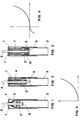
- Figs. 1, 2 and 3
- show schematically in cross section the device of the present invention in which are inserted three different elastic means, respectively a metallic spring of the "bovolo" type, an elastomer and two elastic means placed one against the other;
- Fig. 4
- is a diagram showing the relationship between the deformation and the force being applied with reference to the embodiments of Figs. 1 and 2;
- Fig. 5
- is a diagram showing the relation between the deformation and the force being applied with reference to the embodiment of Fig. 3;
- Figs. 6 and 7
- illustrate a first embodiment of the invention respectively in conditions of compression when the device is functioning and in the conditions of rest during traction;
- Fig. 8
- is an elevational view in cross section of the central hub which is used in the device of Figs. 6 and 7;
- Figs. 9 and 10
- show a planar view respectively from the bottom and from the top of the hub of Fig. 8;
- Fig. 11
- shows the end of the floating shaft which is present in the device of Figs. 6 and 7;
- Fig. 12
- is a planar view of the shaft of Fig. 11;
- Figs. 13 and 14 and Figs. 15 and 16
- illustrate respectively a second and a third embodiment of the invention in conditions of compression and rest;
- Fig. 17
- shows the end of the floating shaft present in the embodiments of Figs. 13 and 16;
- Fig. 18
- shows a transversal cross section of the shaft of Fig. 17.
Claims (13)
- A device for the amortization of rods for skiing, rods for excursions, walking, crutches and similar articles, which device comprises member (1) and element (2), said member (1) and element (2) being generally cylindrical and coaxial with the longitudinal axis of the structure to be amortized, one of said member (1) and element (2) being placed partially within the other with the possibility of sliding with respect to the same corresponding to the stresses being formed on the structure during use following the contact with the bearing surface, and the device additionally comprises an elastic hub placed between said member (1) and element (2), said elastic hub being capable of amortizing said stresses, the device further being characterized by the fact that said elastic hub is firmly anchored with its bases to the corresponding end plates (1') and (2') Of said member (1) and element (2), said elastic hub being capable of amortizing said stresses, the device further being characterized by the fact that said elastic hub is firmly anchored with its bases to the corresponding end plates (1') and (2'), said elastic hub further being capable of carrying out an action of amortization both during the compression and during the traction stage.
- The device according to claim 1 characterized by the fact that said elastic hub (3) is constituted by a conical spring, a bi-conical spring of the type " buvolo".
- The device according to claim 1 characterized by the fact that said elastic hub (4) is constituted by an elastomer.
- The device according to claims 2 and 3 characterized by the fact that said elastic hub is held in guide by a floating shaft (5), said floating shaft being integral with said end plate (1') and going over said end plate (2') said floating shaft being provided at the end thereof with means (6) for stopping the course, said floating shaft (5) being blocked against said end plate (2') at the end of a predetermined traction course.
- The device according to claim 1 characterized by the fact that the amortization action is carried out with two elastic hubs (7) and (8), said two elastic hubs being placed opposite one to the other and acting on the same end plate (2'), said hubs operating in opposition.
- The devise according to claim 5 characterized by the fact that a portion or the entire lateral surface (10) of at least one of said elastic hubs (7) and (8) comes in contact with the containing wall of the corresponding member (1) or element (2).
- The device according to one or more of the preceding claims characterized by the fact that said means (6) is constituted by flexible tongues which are engaged during the phase of return of said floating shaft (5) with the extremity of said shaft thus causing it to stop.
- The device according to one or more of the preceding claims characterized by the factthat said end plate (2') of said element (2) is constituted by a hub (11), said hub being provided with tongues (12), said tongues being flexible and during the condition of compression being open and coming in contact with the body (13) of said floating shaft (5), while in the condition of traction they block said shaft which becomes wedged in the tapered portion (14) of said shaft.
- The device according to one or more of the preceding claims characterized by the fact that said flexible tongues (15) are totally contained within hub (16), said hub (16) constituting said end piate (2'), said tongues becoming engaged within the longitudinal cavities (17) which are formed on the body of said floating shaft (5).
- The device according to one or more of the preceding claims characterized by the fact that at least the portion of the floating shaft (5) which is placed in contact with said end plate (2') has a polygonal section, preferably quadrilateral.
- The device according to one or more of the preceding claims which is being used in skiing, rods for excursions or walking characterized by the fact that it is placed corresponding to the handgrip of said rod.
- The device according to one or more of the preceding claims which is used for skiing rods, rods for excursions or walking which is placed corresponding to the point wherein two components of said rod are joined.
- The device according to one or more of the preceding claims which is used for skiing rods, rods for excursions or walking characterized by the fact that it is placed at least at two points of union of the components which constitute the rod.
Applications Claiming Priority (2)
| Application Number | Priority Date | Filing Date | Title |
|---|---|---|---|
| ITVI970166 | 1997-09-29 | ||
| IT97VI000166A IT1295519B1 (en) | 1997-09-29 | 1997-09-29 | CUSHIONING DEVICE FOR HIKING, WALKING SKI POLES AND CRUTCHES AND SIMILAR |
Publications (3)
| Publication Number | Publication Date |
|---|---|
| EP0904810A2 true EP0904810A2 (en) | 1999-03-31 |
| EP0904810A3 EP0904810A3 (en) | 2000-02-02 |
| EP0904810B1 EP0904810B1 (en) | 2005-07-06 |
Family
ID=11426467
Family Applications (1)
| Application Number | Title | Priority Date | Filing Date |
|---|---|---|---|
| EP98117977A Expired - Lifetime EP0904810B1 (en) | 1997-09-29 | 1998-09-24 | A device for the amortization of ski rods, rods for excursions, for walking, crutches and similar articles |
Country Status (5)
| Country | Link |
|---|---|
| US (1) | US6254134B1 (en) |
| EP (1) | EP0904810B1 (en) |
| AT (1) | ATE299038T1 (en) |
| DE (1) | DE69830771T2 (en) |
| IT (1) | IT1295519B1 (en) |
Cited By (3)
| Publication number | Priority date | Publication date | Assignee | Title |
|---|---|---|---|---|
| DE20117146U1 (en) * | 2001-10-18 | 2003-02-27 | Lenhart, Klaus, 73275 Ohmden | Trekking pole with shock absorber |
| WO2009003298A1 (en) * | 2007-07-03 | 2009-01-08 | Lekisport Ag | Stick with a shock absorber |
| WO2016128945A1 (en) * | 2015-02-12 | 2016-08-18 | Gabel S.R.L. Unipersonale | Vibration absorption system, to be inserted in the poles for nordic walking, trekking and the like |
Families Citing this family (11)
| Publication number | Priority date | Publication date | Assignee | Title |
|---|---|---|---|---|
| IT1315174B1 (en) * | 2000-01-21 | 2003-02-03 | Renato Zaltron | CUSHIONED STICK |
| GB2354939B (en) * | 2000-11-06 | 2001-09-05 | Thomas Francis Mcgrath | Walking aid |
| ITMI20060024U1 (en) * | 2006-01-24 | 2007-07-25 | Spm Spa | JOINTED POLE FOR SKI SLOPES, REINFORCED |
| US8276943B2 (en) * | 2006-11-18 | 2012-10-02 | Black Diamond Equipment, Ltd. | Systems and methods for pole impact force damping |
| USD600002S1 (en) | 2008-11-11 | 2009-09-15 | Alpha Group Investments, Llc | Shock absorbing crutch |
| US7841353B2 (en) * | 2009-02-12 | 2010-11-30 | Ming-Hsien Lee | Foldable walking stick with adjustable length and a shock-proofing mechanism |
| US8528577B2 (en) * | 2010-07-13 | 2013-09-10 | Easton Technical Products, Inc. | Shock absorbing system for trekking poles |
| WO2012162484A2 (en) * | 2011-05-24 | 2012-11-29 | Basham Marshall Aaron Vaughn | Force absorbing device |
| FR3012727B1 (en) | 2013-11-05 | 2017-02-24 | Rossignol Sa | BATON FOR THE PRACTICE OF SLIDING SPORT OR THE MARKET |
| US10898406B2 (en) * | 2019-03-01 | 2021-01-26 | John McAteer | Collapsable safety cane with shock absorbing feature |
| US12185804B2 (en) * | 2023-02-09 | 2025-01-07 | William F McHeffey | Impetus pole |
Family Cites Families (14)
| Publication number | Priority date | Publication date | Assignee | Title |
|---|---|---|---|---|
| US1336844A (en) * | 1919-07-14 | 1920-04-13 | Robert Sommer | Crutch |
| US1753065A (en) * | 1929-07-26 | 1930-04-01 | Thomas E Payne | Crutch attachment |
| US1817829A (en) * | 1930-03-07 | 1931-08-04 | William H Lanning | Crutch attachment |
| US2397499A (en) * | 1945-03-17 | 1946-04-02 | Henri C Mcgowan | Crutch tip construction |
| US2414758A (en) * | 1945-07-14 | 1947-01-21 | Moss John William | Crutch tip and cushioning means therefor |
| US2675014A (en) * | 1952-07-03 | 1954-04-13 | William H Powers | Shock absorbing crutch tip |
| US2888022A (en) * | 1956-11-30 | 1959-05-26 | Walter F Fanning | Shock absorber for orthopedic crutches |
| US3158162A (en) * | 1962-05-09 | 1964-11-24 | Roy C Reel | Blind man's walking cane |
| AT299034B (en) * | 1970-06-29 | 1972-06-12 | Hermann Bruckschweiger | Spring loaded ski stick |
| DE2055597A1 (en) * | 1970-11-12 | 1972-05-18 | Fa. Hermann Schwabe, 7067 Urbach | Ski pole |
| US4061347A (en) * | 1976-06-01 | 1977-12-06 | Allsop Automatic Inc. | Shock-absorbing ski pole grip |
| US4958651A (en) * | 1989-05-09 | 1990-09-25 | Najm Emile G | Impact cushioning and avoiding device |
| IT241871Y1 (en) * | 1996-07-26 | 2001-05-17 | Gabel Srl | STRUCTURE OF CUSHIONED WALKING STICK |
| US5711335A (en) * | 1996-08-28 | 1998-01-27 | Carpin Manufacturing, Inc. | Medical walker foot with collapsible tip |
-
1997
- 1997-09-29 IT IT97VI000166A patent/IT1295519B1/en active IP Right Grant
-
1998
- 1998-09-24 DE DE69830771T patent/DE69830771T2/en not_active Expired - Lifetime
- 1998-09-24 AT AT98117977T patent/ATE299038T1/en not_active IP Right Cessation
- 1998-09-24 EP EP98117977A patent/EP0904810B1/en not_active Expired - Lifetime
- 1998-09-25 US US09/160,694 patent/US6254134B1/en not_active Expired - Fee Related
Cited By (6)
| Publication number | Priority date | Publication date | Assignee | Title |
|---|---|---|---|---|
| DE20117146U1 (en) * | 2001-10-18 | 2003-02-27 | Lenhart, Klaus, 73275 Ohmden | Trekking pole with shock absorber |
| WO2003034859A1 (en) * | 2001-10-18 | 2003-05-01 | Klaus Lenhart | Trekking stick comprising a shock absorber |
| US7229101B2 (en) | 2001-10-18 | 2007-06-12 | Klaus Lenhart | Trekking stick with shock absorber |
| WO2009003298A1 (en) * | 2007-07-03 | 2009-01-08 | Lekisport Ag | Stick with a shock absorber |
| US8474471B2 (en) | 2007-07-03 | 2013-07-02 | Lekisport Ag | Stick with a shock absorber |
| WO2016128945A1 (en) * | 2015-02-12 | 2016-08-18 | Gabel S.R.L. Unipersonale | Vibration absorption system, to be inserted in the poles for nordic walking, trekking and the like |
Also Published As
| Publication number | Publication date |
|---|---|
| US6254134B1 (en) | 2001-07-03 |
| ITVI970166A1 (en) | 1999-03-29 |
| IT1295519B1 (en) | 1999-05-12 |
| ATE299038T1 (en) | 2005-07-15 |
| EP0904810B1 (en) | 2005-07-06 |
| ITVI970166A0 (en) | 1997-09-29 |
| DE69830771D1 (en) | 2005-08-11 |
| DE69830771T2 (en) | 2006-04-20 |
| EP0904810A3 (en) | 2000-02-02 |
Similar Documents
| Publication | Publication Date | Title |
|---|---|---|
| EP0904810A2 (en) | A device for the amortization of ski rods, rods for excursions, for walking, crutches and similar articles | |
| US5720474A (en) | Shock absorbing mechanism of displacement for stick, leg, etc. | |
| US5653767A (en) | Prosthetic foot | |
| US2793036A (en) | Pogo stick | |
| US4332399A (en) | Ski pole | |
| US5114186A (en) | Shock absorbing ski pole | |
| US5957516A (en) | Shock-absorbing tool handle | |
| US5527240A (en) | Gripping power training device | |
| EP0688584B1 (en) | Multi-functional physical exercise device | |
| SU1496628A3 (en) | Tool for drilling holes | |
| JPS5949022B2 (en) | Buffered ski pole | |
| US5683095A (en) | Interface between front and rear ski bindings | |
| US20050129456A1 (en) | Crutch apparatus and method | |
| KR940702989A (en) | DRUM BRAKE TORSION COMPRESSION STRUT SPRING | |
| TW202110698A (en) | Rotation transmission mechanism and motor | |
| JP2019190509A (en) | Rotation transmission mechanism and bicycle including the same | |
| JPH10313921A (en) | Stick with variable pitch spring | |
| KR101714957B1 (en) | Muscle strengthening cane | |
| JP5035826B2 (en) | Walking cane and elastic buffer used therefor | |
| KR20110015203A (en) | Impact reduction and driving force improvement shoes using the principle of spring and lever | |
| SU1409303A1 (en) | Ski stick | |
| KR102341086B1 (en) | Propulsion booster | |
| DE19634604A1 (en) | Skateboard adapted for jumping exercises | |
| US8371994B2 (en) | Adjustable spring device for walking and running | |
| KR20120001846A (en) | Prefab Stick Stopper |
Legal Events
| Date | Code | Title | Description |
|---|---|---|---|
| PUAI | Public reference made under article 153(3) epc to a published international application that has entered the european phase |
Free format text: ORIGINAL CODE: 0009012 |
|
| AK | Designated contracting states |
Kind code of ref document: A2 Designated state(s): AT CH DE FI FR GB IT LI SE |
|
| AX | Request for extension of the european patent |
Free format text: AL;LT;LV;MK;RO;SI |
|
| PUAL | Search report despatched |
Free format text: ORIGINAL CODE: 0009013 |
|
| AK | Designated contracting states |
Kind code of ref document: A3 Designated state(s): AT BE CH CY DE DK ES FI FR GB GR IE IT LI LU MC NL PT SE |
|
| AX | Request for extension of the european patent |
Free format text: AL;LT;LV;MK;RO;SI |
|
| 17P | Request for examination filed |
Effective date: 20000720 |
|
| AKX | Designation fees paid |
Free format text: AT CH DE FI FR GB IT LI SE |
|
| 17Q | First examination report despatched |
Effective date: 20030821 |
|
| GRAP | Despatch of communication of intention to grant a patent |
Free format text: ORIGINAL CODE: EPIDOSNIGR1 |
|
| GRAS | Grant fee paid |
Free format text: ORIGINAL CODE: EPIDOSNIGR3 |
|
| GRAA | (expected) grant |
Free format text: ORIGINAL CODE: 0009210 |
|
| AK | Designated contracting states |
Kind code of ref document: B1 Designated state(s): AT CH DE FI FR GB IT LI SE |
|
| PG25 | Lapsed in a contracting state [announced via postgrant information from national office to epo] |
Ref country code: LI Free format text: LAPSE BECAUSE OF FAILURE TO SUBMIT A TRANSLATION OF THE DESCRIPTION OR TO PAY THE FEE WITHIN THE PRESCRIBED TIME-LIMIT Effective date: 20050706 Ref country code: FI Free format text: LAPSE BECAUSE OF FAILURE TO SUBMIT A TRANSLATION OF THE DESCRIPTION OR TO PAY THE FEE WITHIN THE PRESCRIBED TIME-LIMIT Effective date: 20050706 Ref country code: CH Free format text: LAPSE BECAUSE OF FAILURE TO SUBMIT A TRANSLATION OF THE DESCRIPTION OR TO PAY THE FEE WITHIN THE PRESCRIBED TIME-LIMIT Effective date: 20050706 |
|
| REG | Reference to a national code |
Ref country code: GB Ref legal event code: FG4D |
|
| REG | Reference to a national code |
Ref country code: CH Ref legal event code: EP |
|
| REF | Corresponds to: |
Ref document number: 69830771 Country of ref document: DE Date of ref document: 20050811 Kind code of ref document: P |
|
| PG25 | Lapsed in a contracting state [announced via postgrant information from national office to epo] |
Ref country code: SE Free format text: LAPSE BECAUSE OF FAILURE TO SUBMIT A TRANSLATION OF THE DESCRIPTION OR TO PAY THE FEE WITHIN THE PRESCRIBED TIME-LIMIT Effective date: 20051006 |
|
| REG | Reference to a national code |
Ref country code: CH Ref legal event code: PL |
|
| ET | Fr: translation filed | ||
| PLBE | No opposition filed within time limit |
Free format text: ORIGINAL CODE: 0009261 |
|
| STAA | Information on the status of an ep patent application or granted ep patent |
Free format text: STATUS: NO OPPOSITION FILED WITHIN TIME LIMIT |
|
| 26N | No opposition filed |
Effective date: 20060407 |
|
| PG25 | Lapsed in a contracting state [announced via postgrant information from national office to epo] |
Ref country code: IT Free format text: LAPSE BECAUSE OF NON-PAYMENT OF DUE FEES Effective date: 20070924 |
|
| PGFP | Annual fee paid to national office [announced via postgrant information from national office to epo] |
Ref country code: GB Payment date: 20090908 Year of fee payment: 12 Ref country code: AT Payment date: 20090914 Year of fee payment: 12 |
|
| PGFP | Annual fee paid to national office [announced via postgrant information from national office to epo] |
Ref country code: DE Payment date: 20091117 Year of fee payment: 12 |
|
| GBPC | Gb: european patent ceased through non-payment of renewal fee |
Effective date: 20100924 |
|
| REG | Reference to a national code |
Ref country code: FR Ref legal event code: ST Effective date: 20110531 |
|
| REG | Reference to a national code |
Ref country code: DE Ref legal event code: R119 Ref document number: 69830771 Country of ref document: DE Effective date: 20110401 |
|
| PG25 | Lapsed in a contracting state [announced via postgrant information from national office to epo] |
Ref country code: FR Free format text: LAPSE BECAUSE OF NON-PAYMENT OF DUE FEES Effective date: 20100930 Ref country code: DE Free format text: LAPSE BECAUSE OF NON-PAYMENT OF DUE FEES Effective date: 20110401 |
|
| PGFP | Annual fee paid to national office [announced via postgrant information from national office to epo] |
Ref country code: IT Payment date: 20090903 Year of fee payment: 12 |
|
| PGRI | Patent reinstated in contracting state [announced from national office to epo] |
Ref country code: IT Effective date: 20110616 |
|
| PG25 | Lapsed in a contracting state [announced via postgrant information from national office to epo] |
Ref country code: GB Free format text: LAPSE BECAUSE OF NON-PAYMENT OF DUE FEES Effective date: 20100924 Ref country code: AT Free format text: LAPSE BECAUSE OF NON-PAYMENT OF DUE FEES Effective date: 20100924 |
|
| PGFP | Annual fee paid to national office [announced via postgrant information from national office to epo] |
Ref country code: FR Payment date: 20090925 Year of fee payment: 12 |
|
| PGRI | Patent reinstated in contracting state [announced from national office to epo] |
Ref country code: IT Effective date: 20110616 |