EP0904801A2 - Method of detecting events or conditions in an iontophoretic drug delivery system - Google Patents
Method of detecting events or conditions in an iontophoretic drug delivery system Download PDFInfo
- Publication number
- EP0904801A2 EP0904801A2 EP98306887A EP98306887A EP0904801A2 EP 0904801 A2 EP0904801 A2 EP 0904801A2 EP 98306887 A EP98306887 A EP 98306887A EP 98306887 A EP98306887 A EP 98306887A EP 0904801 A2 EP0904801 A2 EP 0904801A2
- Authority
- EP
- European Patent Office
- Prior art keywords
- current
- voltage
- patch
- controller
- measured
- Prior art date
- Legal status (The legal status is an assumption and is not a legal conclusion. Google has not performed a legal analysis and makes no representation as to the accuracy of the status listed.)
- Withdrawn
Links
- 238000000034 method Methods 0.000 title description 16
- 238000012377 drug delivery Methods 0.000 title description 8
- 230000008859 change Effects 0.000 claims abstract description 28
- 230000009471 action Effects 0.000 claims abstract description 23
- 230000000007 visual effect Effects 0.000 claims description 2
- 239000003814 drug Substances 0.000 description 18
- 229940079593 drug Drugs 0.000 description 17
- 238000005259 measurement Methods 0.000 description 10
- 230000007423 decrease Effects 0.000 description 8
- 239000003792 electrolyte Substances 0.000 description 3
- 150000002500 ions Chemical class 0.000 description 3
- 239000004020 conductor Substances 0.000 description 2
- 230000003247 decreasing effect Effects 0.000 description 2
- 238000001514 detection method Methods 0.000 description 2
- 239000007772 electrode material Substances 0.000 description 2
- 238000012544 monitoring process Methods 0.000 description 2
- 230000001052 transient effect Effects 0.000 description 2
- 230000000694 effects Effects 0.000 description 1
- 238000003487 electrochemical reaction Methods 0.000 description 1
- 230000037406 food intake Effects 0.000 description 1
- 230000006870 function Effects 0.000 description 1
- 238000002347 injection Methods 0.000 description 1
- 239000007924 injection Substances 0.000 description 1
- 238000012986 modification Methods 0.000 description 1
- 230000004048 modification Effects 0.000 description 1
- 230000008569 process Effects 0.000 description 1
- 238000012545 processing Methods 0.000 description 1
- 230000009467 reduction Effects 0.000 description 1
- 230000004044 response Effects 0.000 description 1
- 230000035807 sensation Effects 0.000 description 1
- 229940124597 therapeutic agent Drugs 0.000 description 1
- 230000037317 transdermal delivery Effects 0.000 description 1
Images


Classifications
-
- A—HUMAN NECESSITIES
- A61—MEDICAL OR VETERINARY SCIENCE; HYGIENE
- A61N—ELECTROTHERAPY; MAGNETOTHERAPY; RADIATION THERAPY; ULTRASOUND THERAPY
- A61N1/00—Electrotherapy; Circuits therefor
- A61N1/18—Applying electric currents by contact electrodes
- A61N1/20—Applying electric currents by contact electrodes continuous direct currents
- A61N1/30—Apparatus for iontophoresis, i.e. transfer of media in ionic state by an electromotoric force into the body, or cataphoresis
Definitions
- the invention is in the field of iontophoresis.
- the invention relates to an iontophoretic drug delivery system, having an iontophoretic controller and patch, which automatically detects when certain events or conditions occur in the system.
- Such events or conditions may include the substantial depletion of the conductive material of the electrodes of the iontophoretic patch or failure of the iontophoretic controller.
- the system performs an action such as providing a warning or stopping the supply of iontophoretic current to the iontophoretic patch.
- Iontophoresis is the application of an electrical current to transport ions through intact skin; the ionized species are usually the ionic form of a drug or other therapeutic agent.
- One particularly advantageous application of iontophoresis is the non-invasive transdermal delivery of ionized drugs into a patient. This is done by applying current to the electrodes of the iontophoretic patch. The electrodes are respectively arranged within a drug reservoir, containing the drug ions, and a return reservoir, containing an electrolyte.
- current applied from the iontophoretic current controller forces the ionized drug contained in the drug reservoir through the skin and into the patient.
- Iontophoretic drug delivery offers an alternative and effective method of drug delivery to other drug delivery methods such as passive transdermal patches, needle injection, and oral ingestion, and is an especially effective method for children, the bedridden and the elderly.
- certain conditions can cause a relatively larger amplitude, longer duration, change (up-ramping or down-ramping) of the voltage.
- These conditions include, but are not necessarily limited to: poor contact between the patch and skin, the patch being substantially depleted of drug or other ions, the patch being substantially depleted of electrode material, certain failures of the iontophoretic current controller, an improper electro-chemical reaction, damage to the patch or contacts, and excessive electrical noise from some external source.
- a patient may attempt to reuse a patch having a substantially depleted electrode or drug reservoir, which would also cause an undesirable large amplitude, long duration, voltage increase.
- the present invention advantageously provides an iontophoretic drug delivery system that overcomes the above-described problems by automatically performing an action, such as, for example, performing a warning or stopping the supply of current, when a sufficient up-ramping of voltage has been detected by the controller, thus preventing patient discomfort or drug misdelivery.
- an iontophoretic system having an iontophoretic controller and patch are provided.
- the controller is electrically connected to the two patch electrodes via two electrical connectors, the two electrodes respectively being positioned in an active (drug) reservoir and the return reservoir of the patch.
- the controller includes a current source for supplying current to the electrodes when the controller is turned on, a voltage measuring device for measuring a change in voltage over a predetermined time interval and a comparator for comparing the measured change in voltage to a threshold. The supply of current is stopped, or a warning or some other action is taken, when the comparator determines that the change in voltage over the predetermined time interval exceeds the threshold.
- the iontophoretic controller includes a device for measuring the supplied current over a predetermined time interval, and a comparator compares a measured change in current to a current threshold.
- the controller takes action when the comparator determines that the measured change in current over the predetermined time interval exceeds the current threshold.
- the iontophoretic controller includes a device for determining a load impedance from a measured patch voltage and current. The change in load impedance over a predetermined time interval is determined, and a comparator compares the measured current to an impedance threshold. In this aspect of the invention, the controller takes action when the comparator determines that the measured change in impedance over the predetermined time interval exceeds the impedance threshold.
- the embodiments of the present invention relate to an iontophoretic delivery system 1 illustrated in Fig. 2.
- the iontophoretic delivery system shown in Fig. 2 includes a current controller 12 containing an energy source, such as a battery 10, and connected to a patch 5.
- the patch 5 has an active reservoir 68 and a return reservoir 48 respectively containing a drug D + and an electrolyte.
- the patch 5 also includes a first electrode 60 (an anode), arranged inside the active reservoir 68, and a second electrode 40 (a cathode) arranged inside the return reservoir 48, respectively in contact with the drug and the electrolyte.
- electrode 60 will be the cathode and electrode 40 will be the anode.
- Electrical connectors 2 and 3 respectively carry current between the electrodes 60 and 40 and the controller 12.
- patch 5 When patch 5 is placed on skin 81 of the patient 80, and the controller 12 is turned on to supply current to the electrodes 60 and 40 of patch 5, the drug D + passes through the skin 81 into the patient 80 because the patient's body completes the iontophoretic circuit.
- the controller it is desirable for the controller to take some action when the electrode becomes depleted of conductive material during a treatment, or when a patch already having a spent electrode is mistakenly reused. It is also desirable for the controller to act when there is an indication that the controller is not operating properly. It is also desirable to act if the patch becomes partially or completely disconnected from the skin or is damaged.
- the controller is provided with circuitry for detecting this up-ramping voltage. Upon detection, the controller then automatically takes an action, such as setting off an audio, visual or tactile alarm, or providing some other warning or indication. Alternatively, the supply of current to the patch may be discontinued.
- Fig. 1A shows an example of the delivered patch current over time during iontophoresis
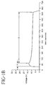
- Fig. 1B shows the corresponding measured voltage
- Fig. 1C shows the resistance of the patch over time, calculated from the measured patch current and voltage.
- the initial portion A of Figs. 1A, 1B and 1C as the current increases, the voltage increases and the resistance decreases.
- portion B of Figs. 1A, 1B and 1C as the current remains constant, the voltage and resistance both monotonically decrease with time.
- a constant rate of current is required to deliver a constant rate of drug (in iontophoresis, it is known that the amount of drug delivered is proportional to the amount of supplied current) during most of the delivery cycle.
- the electrode impedance substantially increases because of the large reduction in conductive surface area. This increasing impedance causes an up-ramping in the measured patch voltage, since the current is controlled to remain substantially constant.
- the controller 12 includes circuitry to measure the voltage across the electrodes at predetermined intervals and compare the change in the measured voltage to a predetermined threshold. If the change exceeds the predetermined threshold, the controller then takes an action, or stops supplying current to the patch. Because there can be a large positive voltage slope during the initial transient period, the measured change in voltage is not compared to the threshold until steady-state drug delivery has already begun.
- the controller circuitry for controlling the current, measuring the patch voltage V and comparing the measured voltage to a threshold is shown in Fig. 3A.
- Current I is supplied to the patch by current source 100.
- Differential amplifier 104 measures the voltage V across the patch.
- the analog voltage measurements are converted to digital values by the analog to digital (A/D) converter 108 and read by a microprocessor 110.
- the microprocessor controls the time interval between voltage measurements, calculates a difference between the voltage measurements and compares this voltage difference to a predetermined (voltage) threshold, as will be explained in more detail below in reference to Figs. 4 and 5.
- the microprocessor turns off the current source 100 through control line 120, or activates an alarm 112 through control line 122, or both.
- a comparison of the voltage to the predetermined threshold may be performed in hardware by a voltage comparator and a state machine, as well as by software in the microprocessor.
- means may be provided for switching between the connected patch and an auxiliary, unconnected patch.
- These means may include a microprocessor-controlled, logic-controlled or mechanical switch connected to those two patches. In this case, the action taken by the controller upon the measured or computed parameter exceeding a threshold would be to cause the switch to disconnect the presumably faulty patch and connect the auxiliary patch to the controller.
- a second embodiment of the present invention shown in Fig. 3B, the patch voltage is controlled, while the supply current I is measured and comparing the measured voltage to a threshold is shown in Fig. 3A.
- Current I is supplied to the patch by battery 101 through a current sensing resistor 102 when switch 103 is closed.
- Switch 103 may be any type of switch, but is preferably configured as a MOSFET.
- Differential amplifier 106 measures the voltage across the current sensing resistor 102, V R , thereby measuring the current I flowing through the patch, equal to V R /R.
- the analog current measurements are converted to digital values by the A/D converter 108 and read by the microprocessor 110.
- the microprocessor controls the time interval between current measurements, takes a difference between the current measurements and compares this current difference to a predetermined (current) threshold. When the current difference exceeds the predetermined threshold, an error condition is said to exist, and the microprocessor through control line 120 turns off the current I by opening switch 103, or activates an alarm 112 through control line 122, or both.
- the current is controlled, both patch voltage V and current I are measured, and a load impedance (V/I) is calculated therefrom.
- Current I is supplied to the patch by current source 100.
- Differential amplifier 104 measures the voltage V across the patch and differential amplifier 106 measures the voltage across the current sensing resistor 102, V R , thereby measuring the current I flowing through the patch, equal to V R /R.
- the analog voltage measurements are converted to digital values by the analog to digital (A/D) converter 108 and read by a microprocessor 110.
- the A/D converter output is multiplexed to provide selectively digital voltage V and current I values.
- the microprocessor controls the time interval between voltage or current measurements.
- the microprocessor computes a load impedance from a digital voltage measurement and a digital current measurement determined at a given time. The microprocessor then calculates a difference between two load impedances computed respectively at two different times and compares this load impedance difference to a predetermined (load impedance) threshold. When the load impedance difference exceeds the predetermined threshold, an error condition is said to exist, and the microprocessor turns off the current source 100 through control line 120, or activates an alarm 112 through control line 122, or both.
- a method for monitoring the patch voltage as measured by the circuit of Fig. 3A is illustrated by the flowchart of Fig. 4.
- This method is based on the above-described premise that in steady-state, constant current delivery, the measured voltage is expected to monotonically decrease, and that a problem may have occurred if the measured voltage rises above a minimum measured voltage by a predetermined amount.
- step S1 one end of the patch is attached to the patient while the other end of the patch is inserted into the controller.
- the controller is switched on, either manually or automatically, supplying current to the patch.
- step S2 after steady-state iontophoresis has been achieved after a predetermined amount of time, the above-described controller circuitry measures the voltage across the electrodes of the patch over a predetermined time interval, for example, one second.
- step S3 the controller compares this voltage to the lowest voltage, V min , thus far measured. If the measured voltage is greater than or equal to V min , then in step S4 the controller compares the difference between the measured voltage and the minimum measured voltage to the predetermined threshold value (V - V min > threshold). If not, the measured voltage has decreased as compared to the lowest voltage thus measured, and thus V min is set to that measured voltage in step S5, and the controller continues to measure the voltage in step S2.
- step S4 the controller compares the difference between the measured voltage and the minimum measured voltage to the predetermined threshold, for example, +N volts. If that difference has not exceeded the predetermined threshold, then step S2 is repeated. On the other hand, if the difference exceeds the predetermined threshold, some problem may have occurred, and the current supplied to the patch is stopped or some other action is taken, as indicated by step S6.
- the predetermined threshold for example, +N volts.
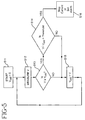
- step S11 another method for monitoring the patch voltage as measured by the circuit of Fig. 3A is illustrated by the flowchart of Fig. 5. This method is based on the above-described premise that in steady-state, constant current delivery, the voltage slope is expected to decrease, and that a problem may have occurred if the measured voltage slope increases by a predetermined amount.
- step S11 one end of the patch is attached to the patient while the other end of the patch is inserted into the controller. The controller is switched on, either manually or automatically, supplying current to the patch.
- step S12 after steady-state iontophoresis has been achieved after a predetermined amount of time, the above-described controller circuitry measures the voltage across the electrodes of the patch over a predetermined time interval, for example, one second.
- step S13 the controller compares the current voltage sample (V) to the previous voltage sample, V old . If V is greater than or equal to V old , then in step S14 the controller compares the change in voltage between samples to a predetermined slope threshold value (V - V old > slope threshold). If not, V old is set to the current voltage sample V in step S15, and the controller continues to measure the voltage in step S12.
- V current voltage sample
- V old a predetermined slope threshold value
- step S14 the controller compares the difference between the current and previous voltage samples to the predetermined slope threshold, for example, +N volts per unit of time, such as, for example, one second intervals. In essence, the comparison is between the measured instantaneous voltage slope and the voltage slope threshold. If the difference has not exceeded the predetermined slope threshold, then V old is set to the current voltage sample V in step S15, and the controller continues to measure the voltage in step S12. On the other hand, if the difference exceeds the predetermined voltage slope threshold, then some problem may have occurred, and the current supplied to the patch is stopped or some other action is taken, as indicated by step S16.
- the slope threshold may be a large negative number, indicating that a large drop in voltage has occurred. This too may indicate that a problem has occurred, or simply that the delivery cycle is over if current is no longer being supplied through the patch. In either case, a warning or some other action may be taken at that time.
- Variations in the method illustrated by Fig. 5 may include the following.
- the controller may determine only whether a change in the "sign" (from negative to positive) of the difference between V and V old has occurred. This is equivalent to setting the predetermined slope threshold to zero volts/sec. This variation is sensitive to any positive changes in voltage. However, in this case, a small positive voltage change caused by patient movement or electrical noise may cause the controller to take action or to turn off the current before the electrode is actually depleted.
- the controller may require that the difference V - V old exceeds the predetermined slope threshold and that V itself exceed a minimum voltage threshold before it takes action.
- the supplied current may be measured by the controller.
- the above-described methods of Figs. 4 and 5 would use the measured currents instead of the measured voltages.
- both the patch voltage and the supplied current may be measured and a load impedance calculated therefrom. In this case, the above-described methods of Figs. 4 and 5 would use the calculated load impedances instead of the measured voltages.
- any of the various combinations of voltage V, voltage difference (V - V min or V - V old ), current I, current difference (I - I min or I - I old ), impedance Z, and impedance difference (Z - Z min or Z - Z old ) may be used to detect whether a problem may have occurred.
- any combination of voltage, current or impedance may be measured, compared and acted upon.
- the source of power may be a constant or time-varying power source, and may be a current source, a voltage source or a Thevenin equivalent source.
- the voltage slope threshold or the voltage threshold, or both, or any other threshold may be predetermined, or may be automatically determined by the controller. Methods for automatically determining thresholds are known to those skilled in the signal processing art.
- the device may measure the voltage, current or impedance waveform over a predetermined time interval, and a matched filter or correlator circuit may be used to detect any significant variance of the measured voltage, current or impedance waveform from a respective expected voltage, current or impedance waveform.
Landscapes
- Health & Medical Sciences (AREA)
- Engineering & Computer Science (AREA)
- Biomedical Technology (AREA)
- Nuclear Medicine, Radiotherapy & Molecular Imaging (AREA)
- Radiology & Medical Imaging (AREA)
- Life Sciences & Earth Sciences (AREA)
- Animal Behavior & Ethology (AREA)
- General Health & Medical Sciences (AREA)
- Public Health (AREA)
- Veterinary Medicine (AREA)
- Electrotherapy Devices (AREA)
- Investigating Or Analyzing Materials By The Use Of Electric Means (AREA)
Abstract
Description
Claims (10)
- An iontophoretic controller, connectable to a patch having a plurality of electrodes via a respective plurality of electrical connectors, at least two of said plurality of electrodes respectively positioned in an active reservoir and a return reservoir of the patch, said controller comprising:a power source for supplying power to the patch when said controller is turned on;means for measuring a waveform of the patch over a predetermined time interval; andmeans for comparing the measured waveform to a predetermined waveform, wherein said controller takes an action when said comparing means detects a difference between the measured waveform and the predetermined waveform.
- An iontophoretic controller according to claim 1, wherein the measured waveforms are selected from voltage waveforms, current waveforms, and the predetermined waveforms are independently selected from voltage waveforms, current waveforms and impedance waveforms.
- An iontophoretic controller, connectable to a patch having a plurality of electrodes via a respective plurality of electrical connectors, at least two of said plurality of electrodes respectively positioned in an active reservoir and a return reservoir of the patch, said controller comprising:means for supplying a current through the patch when said controller is activated;means for measuring a change in a voltage across the patch over a predetermined time interval; andmeans for comparing the measured change in voltage to a threshold, wherein said controller takes an action when said comparing means determines that the change in measured voltage exceeds the threshold.
- An iontophoretic controller according to claim 1 or claim 3, wherein the action taken is a warning action.
- An iontophoretic controller according to claim 4, wherein the warning action is selected from causing an audio alarm, causing a visual alarm, causing a tactile alarm, and discontinuing the supply of current by said current supplying means.
- An iontophoretic controller, connectable to a patch having a plurality of electrodes via a respective plurality of electrical connectors, at least two of said plurality of electrodes respectively positioned in an active reservoir and a return reservoir of the patch, said controller comprising:means for controlling a voltage across the patch when said controller is activated;means for measuring a change in a current supplied through the patch over a predetermined time interval; andmeans for comparing the measured change in a current to a threshold, wherein said controller takes an action when said comparing means determines that the change in measured current exceeds the threshold.
- An iontophoretic controller according to claim 6, wherein the current supplying means comprises a battery serially connected to a switch, said current measuring means comprises a resistor, a differential amplifier for measuring the voltage across said resistor so as to measure the current, and an analog to digital converter for converting the measured current to a digital current value, and said comparing means comprises a microprocessor which compares the digital current values.
- An iontophoretic controller according to claim 7, wherein the action taken includes stopping the application of voltage by opening said switch.
- An iontophoretic controller, connectable to a patch having a plurality of electrodes via a respective plurality of electrical connectors, at least two of said plurality of electrodes respectively positioned in an active reservoir and a return reservoir of the patch, said controller comprising:means for supplying a current through the patch when said controller is activated;means for measuring a change in a voltage across the patch over a predetermined time interval;means for measuring a change in current supplied through the patch over the predetermined time interval;means for computing a change in load impedance from the measured change in voltage and current over the predetermined time interval; andmeans for comparing the measured change in impedance to a threshold, wherein said controller takes an action when said comparing means determines that the chance in computed load impedance exceeds the threshold.
- An iontophoretic controller according to claim 9, wherein the current supplying means comprises a current source, said voltage measuring means comprises a differential amplifier to measure the voltage across the patch and an analog to digital converter to convert the measured voltage to a digital voltage value, said current measuring means comprises a resistor, a differential amplifier for measuring the voltage across said resistor so as to measure the current, and the analog to digital converter for converting the measured current to a digital current value, and said comparing means comprises a microprocessor which computes the load impedences from the digital voltage and current values compares the computed load impedences.
Applications Claiming Priority (2)
| Application Number | Priority Date | Filing Date | Title |
|---|---|---|---|
| US924764 | 1997-08-27 | ||
| US08/924,764 US6047208A (en) | 1997-08-27 | 1997-08-27 | Iontophoretic controller |
Publications (2)
| Publication Number | Publication Date |
|---|---|
| EP0904801A2 true EP0904801A2 (en) | 1999-03-31 |
| EP0904801A3 EP0904801A3 (en) | 2000-01-05 |
Family
ID=25450691
Family Applications (1)
| Application Number | Title | Priority Date | Filing Date |
|---|---|---|---|
| EP98306887A Withdrawn EP0904801A3 (en) | 1997-08-27 | 1998-08-27 | Method of detecting events or conditions in an iontophoretic drug delivery system |
Country Status (5)
| Country | Link |
|---|---|
| US (1) | US6047208A (en) |
| EP (1) | EP0904801A3 (en) |
| JP (1) | JPH11128369A (en) |
| AU (1) | AU8192698A (en) |
| CA (1) | CA2245915A1 (en) |
Cited By (8)
| Publication number | Priority date | Publication date | Assignee | Title |
|---|---|---|---|---|
| WO2003037425A1 (en) * | 2001-10-31 | 2003-05-08 | R & R Ventures Incorporation | Iontophoresis device |
| WO2003059438A3 (en) * | 2002-01-16 | 2004-02-12 | Andrew Leith | Apparatus for the treatment of muscular and skeletal injuries |
| WO2007041001A3 (en) * | 2005-09-30 | 2007-08-16 | Transcutaneous Tech Inc | Synchronization apparatus and method for iontophoresis device to deliver active agents to biological interfaces |
| WO2008030503A2 (en) | 2006-09-05 | 2008-03-13 | Tti Ellebeau, Inc. | Impedance systems, devices, and methods for evaluating iontophoretic properties of compounds |
| WO2008030496A3 (en) * | 2006-09-05 | 2008-04-24 | Tti Ellebeau Inc | Non-destructive systems, devices, and methods for evaluating iontophoresis drug delivery devices |
| US8062783B2 (en) | 2006-12-01 | 2011-11-22 | Tti Ellebeau, Inc. | Systems, devices, and methods for powering and/or controlling devices, for instance transdermal delivery devices |
| ITTO20110374A1 (en) * | 2011-04-29 | 2012-10-30 | Igea S P A | METHOD OF CONTROL OF AN ELECTRO-PORTION DEVICE |
| EP1902749A3 (en) * | 2006-09-06 | 2014-06-04 | Iomed, Inc. | Iontophoresis apparatus |
Families Citing this family (81)
| Publication number | Priority date | Publication date | Assignee | Title |
|---|---|---|---|---|
| JP2000237330A (en) * | 1999-02-24 | 2000-09-05 | Hisamitsu Pharmaceut Co Inc | Device for iontophoresis |
| US6256533B1 (en) * | 1999-06-09 | 2001-07-03 | The Procter & Gamble Company | Apparatus and method for using an intracutaneous microneedle array |
| US6379324B1 (en) | 1999-06-09 | 2002-04-30 | The Procter & Gamble Company | Intracutaneous microneedle array apparatus |
| JP4162813B2 (en) * | 1999-10-28 | 2008-10-08 | 久光製薬株式会社 | Iontophoresis device |
| AU2001264759B2 (en) * | 2000-05-22 | 2006-06-01 | Merck & Co., Inc. | System and method for assessing the performance of a pharmaceutical agent delivery system |
| US6565532B1 (en) | 2000-07-12 | 2003-05-20 | The Procter & Gamble Company | Microneedle apparatus used for marking skin and for dispensing semi-permanent subcutaneous makeup |
| US7828827B2 (en) | 2002-05-24 | 2010-11-09 | Corium International, Inc. | Method of exfoliation of skin using closely-packed microstructures |
| US7108681B2 (en) | 2000-10-16 | 2006-09-19 | Corium International, Inc. | Microstructures for delivering a composition cutaneously to skin |
| US7131987B2 (en) * | 2000-10-16 | 2006-11-07 | Corium International, Inc. | Microstructures and method for treating and conditioning skin which cause less irritation during exfoliation |
| US6560483B1 (en) | 2000-10-18 | 2003-05-06 | Minnesota High-Tech Resources, Llc | Iontophoretic delivery patch |
| US6663820B2 (en) | 2001-03-14 | 2003-12-16 | The Procter & Gamble Company | Method of manufacturing microneedle structures using soft lithography and photolithography |
| US6591124B2 (en) | 2001-05-11 | 2003-07-08 | The Procter & Gamble Company | Portable interstitial fluid monitoring system |
| BR0210833A (en) * | 2001-07-06 | 2004-06-22 | Aspect Medical Systems Inc | System and method for bioelectrical impedance measurement in the presence of interference |
| US20040087992A1 (en) * | 2002-08-09 | 2004-05-06 | Vladimir Gartstein | Microstructures for delivering a composition cutaneously to skin using rotatable structures |
| DE10205373B4 (en) * | 2002-02-09 | 2007-07-19 | Aloys Wobben | Fire protection |
| US7578954B2 (en) * | 2003-02-24 | 2009-08-25 | Corium International, Inc. | Method for manufacturing microstructures having multiple microelements with through-holes |
| US8017145B2 (en) * | 2003-12-22 | 2011-09-13 | Conopco, Inc. | Exfoliating personal care wipe article containing an array of projections |
| WO2005094526A2 (en) * | 2004-03-24 | 2005-10-13 | Corium International, Inc. | Transdermal delivery device |
| US20060095001A1 (en) * | 2004-10-29 | 2006-05-04 | Transcutaneous Technologies Inc. | Electrode and iontophoresis device |
| US20060135906A1 (en) * | 2004-11-16 | 2006-06-22 | Akihiko Matsumura | Iontophoretic device and method for administering immune response-enhancing agents and compositions |
| US7856263B2 (en) | 2005-04-22 | 2010-12-21 | Travanti Pharma Inc. | Transdermal systems for the delivery of therapeutic agents including granisetron using iontophoresis |
| JP2006334164A (en) * | 2005-06-02 | 2006-12-14 | Transcutaneous Technologies Inc | Iontophoresis apparatus and method for controlling the same |
| JP2006346368A (en) * | 2005-06-20 | 2006-12-28 | Transcutaneous Technologies Inc | Iontophoresis apparatus and manufacturing method |
| JP2007000342A (en) * | 2005-06-23 | 2007-01-11 | Transcutaneous Technologies Inc | Iontophoresis device for controlling quantity and time of dosing a plurality of medicaments |
| JPWO2007010900A1 (en) * | 2005-07-15 | 2009-01-29 | Tti・エルビュー株式会社 | Patch for percutaneous absorption with ion position display function and iontophoresis device |
| US8295922B2 (en) | 2005-08-08 | 2012-10-23 | Tti Ellebeau, Inc. | Iontophoresis device |
| US8386030B2 (en) * | 2005-08-08 | 2013-02-26 | Tti Ellebeau, Inc. | Iontophoresis device |
| US20070088331A1 (en) * | 2005-08-18 | 2007-04-19 | Transcutaneous Technologies Inc. | Method and apparatus for managing active agent usage, and active agent injecting device |
| US20070088332A1 (en) * | 2005-08-22 | 2007-04-19 | Transcutaneous Technologies Inc. | Iontophoresis device |
| US20090254018A1 (en) * | 2005-08-24 | 2009-10-08 | Mizuo Nakayama | Electrode assembly for freezing-type iontophoresis device |
| US7756576B2 (en) * | 2005-08-26 | 2010-07-13 | Biosense Webster, Inc. | Position sensing and detection of skin impedance |
| WO2007026672A1 (en) * | 2005-08-29 | 2007-03-08 | Transcu Ltd. | General-purpose electrolyte composition for iontophoresis |
| WO2007029611A1 (en) * | 2005-09-06 | 2007-03-15 | Tti Ellebeau, Inc. | Iontophoresis device |
| US20070112294A1 (en) * | 2005-09-14 | 2007-05-17 | Transcutaneous Technologies Inc. | Iontophoresis device |
| KR20080047600A (en) * | 2005-09-15 | 2008-05-29 | 티티아이 엘뷰 가부시키가이샤 | Rod type iontophoresis device |
| KR20080056200A (en) * | 2005-09-16 | 2008-06-20 | 티티아이 엘뷰 가부시키가이샤 | Catheter type iontophoresis device |
| JPWO2007037324A1 (en) * | 2005-09-28 | 2009-04-09 | Tti・エルビュー株式会社 | Electrode structure for dry iontophoresis |
| JP2009509677A (en) * | 2005-09-30 | 2009-03-12 | Tti・エルビュー株式会社 | Iontophoretic delivery of vesicle encapsulated active substances |
| US20070078376A1 (en) * | 2005-09-30 | 2007-04-05 | Smith Gregory A | Functionalized microneedles transdermal drug delivery systems, devices, and methods |
| EP1944057A4 (en) * | 2005-09-30 | 2009-02-18 | Tti Ellebeau Inc | Iontophoresis apparatus capable of controlling dose and timing of administration of sleep inducer and analeptic agent |
| KR20080080087A (en) * | 2005-09-30 | 2008-09-02 | 티티아이 엘뷰 가부시키가이샤 | Transdermal Drug Delivery System, Apparatus and Method Using Novel Pharmaceutical Carrier |
| AU2006299520A1 (en) * | 2005-09-30 | 2007-04-12 | Tti Ellebeau, Inc. | Iontophoresis device to deliver multiple active agents to biological interfaces |
| US20070135754A1 (en) * | 2005-09-30 | 2007-06-14 | Hidero Akiyama | Electrode assembly for iontophoresis for administering active agent enclosed in nanoparticle and iontophoresis device using the same |
| EP1928542A1 (en) * | 2005-09-30 | 2008-06-11 | Tti Ellebeau, Inc. | Method and system to detect malfunctions in an iontophoresis device that delivers active agents to biological interfaces |
| US20090299265A1 (en) * | 2005-09-30 | 2009-12-03 | Tti Ellebeau, Inc. | Electrode Assembly for Iontophoresis Having Shape-Memory Separator and Iontophoresis Device Using the Same |
| US20070197955A1 (en) * | 2005-10-12 | 2007-08-23 | Transcutaneous Technologies Inc. | Mucous membrane adhesion-type iontophoresis device |
| US20080033338A1 (en) * | 2005-12-28 | 2008-02-07 | Smith Gregory A | Electroosmotic pump apparatus and method to deliver active agents to biological interfaces |
| US20080033398A1 (en) * | 2005-12-29 | 2008-02-07 | Transcutaneous Technologies Inc. | Device and method for enhancing immune response by electrical stimulation |
| EP1965858A2 (en) * | 2005-12-30 | 2008-09-10 | Tti Ellebeau, Inc. | System and method for remote based control of an iontophoresis device |
| US20080077076A1 (en) * | 2006-08-29 | 2008-03-27 | Transcutaneous Technologies Inc. | Iontophoresis device and method for operation with a usb (universal serial bus) power source |
| CN101528300A (en) * | 2006-09-05 | 2009-09-09 | Tti优而美株式会社 | Transdermal drug delivery systems, devices, and methods using inductive power supplies |
| US8214030B2 (en) * | 2006-09-06 | 2012-07-03 | Encore Medical Asset Corporation | Iontophoresis apparatus and method |
| US7996077B2 (en) * | 2006-09-06 | 2011-08-09 | Encore Medical Asset Corporation | Iontophoresis apparatus and method |
| US8821446B2 (en) * | 2007-01-22 | 2014-09-02 | Corium International, Inc. | Applicators for microneedles |
| US20080188791A1 (en) * | 2007-02-02 | 2008-08-07 | Difiore Attilio E | Active iontophoresis delivery system |
| ES2817249T3 (en) | 2007-04-16 | 2021-04-06 | Corium Inc | Microneedle matrices obtained by dissolution and casting containing an active principle |
| WO2008131072A1 (en) * | 2007-04-17 | 2008-10-30 | Transport Pharmaceuticals, Inc. | Current density detection and control system and method for an electrokinetic delivery of medicaments |
| US8197844B2 (en) | 2007-06-08 | 2012-06-12 | Activatek, Inc. | Active electrode for transdermal medicament administration |
| WO2009048607A1 (en) | 2007-10-10 | 2009-04-16 | Corium International, Inc. | Vaccine delivery via microneedle arrays |
| JP5178132B2 (en) * | 2007-10-11 | 2013-04-10 | キヤノン株式会社 | Image processing system and image processing method |
| US8862223B2 (en) | 2008-01-18 | 2014-10-14 | Activatek, Inc. | Active transdermal medicament patch and circuit board for same |
| EP2429627B1 (en) * | 2009-04-24 | 2017-06-14 | Corium International, Inc. | Methods for manufacturing microprojection arrays |
| TW201121604A (en) * | 2009-06-09 | 2011-07-01 | Tti Ellebeau Inc | Long life high capacity electrode, device, and method of manufacture |
| WO2011100376A2 (en) | 2010-02-10 | 2011-08-18 | Incube Labs, Llc | Methods and architecture for power optimization of iontophoretic transdermal drug delivery |
| EP2566501B1 (en) | 2010-05-04 | 2019-03-13 | Corium International, Inc. | Method and device for transdermal delivery of parathyroid hormone using a microprojection array |
| US8428709B1 (en) | 2012-06-11 | 2013-04-23 | Incline Therapeutics, Inc. | Current control for electrotransport drug delivery |
| US8428708B1 (en) | 2012-05-21 | 2013-04-23 | Incline Therapeutics, Inc. | Self-test for analgesic product |
| US8781571B2 (en) * | 2011-03-31 | 2014-07-15 | Incline Therapeutics, Inc. | Switch validation circuit and method |
| US9731121B2 (en) * | 2011-03-31 | 2017-08-15 | Incline Therapeutics, Inc. | Switch validation circuit and method |
| EP2934660B1 (en) | 2012-12-21 | 2019-07-17 | Corium, Inc. | Microarray for delivery of therapeutic agent and method of making same |
| EP4094799A1 (en) | 2013-03-12 | 2022-11-30 | Corium, Inc. | Microprojection applicators |
| WO2014150285A2 (en) | 2013-03-15 | 2014-09-25 | Corium International, Inc. | Multiple impact microprojection applicators and methods of use |
| US10384046B2 (en) | 2013-03-15 | 2019-08-20 | Corium, Inc. | Microarray for delivery of therapeutic agent and methods of use |
| EP2968119B1 (en) | 2013-03-15 | 2019-09-18 | Corium International, Inc. | Microarray for delivery of therapeutic agent, methods of use, and methods of making |
| US10384045B2 (en) | 2013-03-15 | 2019-08-20 | Corium, Inc. | Microarray with polymer-free microstructures, methods of making, and methods of use |
| DE112014006628T5 (en) * | 2014-04-29 | 2017-02-09 | K-Healthwear Co., Ltd. | Iontophoresis injection device and injection method |
| CA2949709A1 (en) * | 2014-06-04 | 2015-12-10 | Incline Therapeutics, Inc. | Switch validation circuit and method |
| US10624843B2 (en) | 2014-09-04 | 2020-04-21 | Corium, Inc. | Microstructure array, methods of making, and methods of use |
| US10857093B2 (en) | 2015-06-29 | 2020-12-08 | Corium, Inc. | Microarray for delivery of therapeutic agent, methods of use, and methods of making |
| KR20220050676A (en) * | 2020-10-16 | 2022-04-25 | 삼성전자주식회사 | Apparatus for measurering impedence |
| CN115999052B (en) * | 2021-10-21 | 2025-07-25 | 未来穿戴技术股份有限公司 | Detection method for blockage of seepage hole, wearable massage equipment and storage medium |
Family Cites Families (13)
| Publication number | Priority date | Publication date | Assignee | Title |
|---|---|---|---|---|
| US4292968A (en) * | 1979-11-26 | 1981-10-06 | Sybron Corporation | Electric supply for ion therapy |
| EP0092015A1 (en) * | 1982-04-16 | 1983-10-26 | Roland Brodard | Ionizing device |
| US5224928A (en) * | 1983-08-18 | 1993-07-06 | Drug Delivery Systems Inc. | Mounting system for transdermal drug applicator |
| US4822334A (en) * | 1986-12-04 | 1989-04-18 | Robert Tapper | Electrical dosimetry control system |
| US5047007A (en) * | 1989-12-22 | 1991-09-10 | Medtronic, Inc. | Method and apparatus for pulsed iontophoretic drug delivery |
| US5213568A (en) * | 1990-03-30 | 1993-05-25 | Medtronic Inc. | Activity controlled electrotransport drug delivery device |
| US5254081A (en) * | 1991-02-01 | 1993-10-19 | Empi, Inc. | Multiple site drug iontophoresis electronic device and method |
| US5571149A (en) * | 1991-05-21 | 1996-11-05 | E.P., Inc. | Non-intrusive analgesic neuroaugmentive and iontophoretic delivery apparatus and management system |
| US5246418A (en) * | 1991-12-17 | 1993-09-21 | Becton Dickinson And Company | Iontophresis system having features for reducing skin irritation |
| US5306235A (en) * | 1992-09-30 | 1994-04-26 | Becton Dickinson And Company | Failsafe iontophoresis drug delivery system |
| US6167301A (en) * | 1995-08-29 | 2000-12-26 | Flower; Ronald J. | Iontophoretic drug delivery device having high-efficiency DC-to-DC energy conversion circuit |
| US5688232A (en) * | 1995-09-28 | 1997-11-18 | Becton Dickinson And Company | Iontophoretic drug delivery device having an improved controller |
| FR2755842B1 (en) * | 1996-11-19 | 1999-04-23 | Lhd Lab Hygiene Dietetique | METHOD FOR MEASURING THE SKIN RESISTANCE OF A PATIENT SUBJECT TO A TRANSDERMAL ADMINISTRATION OF MEDICAMENT |
-
1997
- 1997-08-27 US US08/924,764 patent/US6047208A/en not_active Expired - Fee Related
-
1998
- 1998-08-26 CA CA002245915A patent/CA2245915A1/en not_active Abandoned
- 1998-08-26 AU AU81926/98A patent/AU8192698A/en not_active Abandoned
- 1998-08-27 EP EP98306887A patent/EP0904801A3/en not_active Withdrawn
- 1998-08-27 JP JP10242374A patent/JPH11128369A/en active Pending
Non-Patent Citations (1)
| Title |
|---|
| None |
Cited By (14)
| Publication number | Priority date | Publication date | Assignee | Title |
|---|---|---|---|---|
| WO2003037425A1 (en) * | 2001-10-31 | 2003-05-08 | R & R Ventures Incorporation | Iontophoresis device |
| WO2003059438A3 (en) * | 2002-01-16 | 2004-02-12 | Andrew Leith | Apparatus for the treatment of muscular and skeletal injuries |
| GB2397531A (en) * | 2002-01-16 | 2004-07-28 | Andrew Leith | Apparatus for the treatment of muscular and skeletal injuries |
| WO2007041001A3 (en) * | 2005-09-30 | 2007-08-16 | Transcutaneous Tech Inc | Synchronization apparatus and method for iontophoresis device to deliver active agents to biological interfaces |
| WO2008030503A3 (en) * | 2006-09-05 | 2008-07-24 | Tti Ellebeau Inc | Impedance systems, devices, and methods for evaluating iontophoretic properties of compounds |
| WO2008030496A3 (en) * | 2006-09-05 | 2008-04-24 | Tti Ellebeau Inc | Non-destructive systems, devices, and methods for evaluating iontophoresis drug delivery devices |
| WO2008030503A2 (en) | 2006-09-05 | 2008-03-13 | Tti Ellebeau, Inc. | Impedance systems, devices, and methods for evaluating iontophoretic properties of compounds |
| US7720622B2 (en) | 2006-09-05 | 2010-05-18 | Tti Ellebeau, Inc. | Non-destructive systems, devices, and methods for evaluating iontophoresis drug delivery devices |
| US7998745B2 (en) | 2006-09-05 | 2011-08-16 | Tti Ellebeau, Inc. | Impedance systems, devices, and methods for evaluating iontophoretic properties of compounds |
| EP1902749A3 (en) * | 2006-09-06 | 2014-06-04 | Iomed, Inc. | Iontophoresis apparatus |
| US8062783B2 (en) | 2006-12-01 | 2011-11-22 | Tti Ellebeau, Inc. | Systems, devices, and methods for powering and/or controlling devices, for instance transdermal delivery devices |
| ITTO20110374A1 (en) * | 2011-04-29 | 2012-10-30 | Igea S P A | METHOD OF CONTROL OF AN ELECTRO-PORTION DEVICE |
| WO2012147072A1 (en) * | 2011-04-29 | 2012-11-01 | Igea S.P.A. | Method for controlling an electroporation device |
| US9314621B2 (en) | 2011-04-29 | 2016-04-19 | Igea S.P.A. | Method for controlling an electroporation device |
Also Published As
| Publication number | Publication date |
|---|---|
| JPH11128369A (en) | 1999-05-18 |
| CA2245915A1 (en) | 1999-02-27 |
| US6047208A (en) | 2000-04-04 |
| AU8192698A (en) | 1999-03-11 |
| EP0904801A3 (en) | 2000-01-05 |
Similar Documents
| Publication | Publication Date | Title |
|---|---|---|
| US6047208A (en) | Iontophoretic controller | |
| JP4162813B2 (en) | Iontophoresis device | |
| JPH11128369A5 (en) | ||
| US7027859B1 (en) | Electrotransport delivery device having improved safety and reduced abuse potential | |
| GB2064178A (en) | Electrical supply for ion therapy | |
| CA1101934A (en) | Body tissue stimulation apparatus with warning device | |
| EP0547482B1 (en) | Iontophoresis system having features for reducing skin irritation | |
| US6442422B1 (en) | Compliance monitoring apparatus and method | |
| US6391015B1 (en) | Method for measuring the cutaneous electrical resistance of a patient subjected to transdermal administration of medicine | |
| JPH1189944A (en) | Ion introduction drug supply system | |
| EP0971769B1 (en) | Automatic switch off iontophoretic system | |
| EP1163926A1 (en) | Device for iontophoresis | |
| EP0367338B1 (en) | Electrotherapy apparatus | |
| JP3036068U (en) | Low frequency electrical stimulator | |
| JPH0975419A (en) | Sensor for good conductive circuit | |
| CA2272870A1 (en) | Method for measuring the cutaneous electric resistance of a patient subjected to transdermal administration of medicine |
Legal Events
| Date | Code | Title | Description |
|---|---|---|---|
| PUAI | Public reference made under article 153(3) epc to a published international application that has entered the european phase |
Free format text: ORIGINAL CODE: 0009012 |
|
| AK | Designated contracting states |
Kind code of ref document: A2 Designated state(s): DE ES FR GB IT |
|
| AX | Request for extension of the european patent |
Free format text: AL;LT;LV;MK;RO;SI |
|
| PUAL | Search report despatched |
Free format text: ORIGINAL CODE: 0009013 |
|
| AK | Designated contracting states |
Kind code of ref document: A3 Designated state(s): AT BE CH CY DE DK ES FI FR GB GR IE IT LI LU MC NL PT SE |
|
| AX | Request for extension of the european patent |
Free format text: AL;LT;LV;MK;RO;SI |
|
| 17P | Request for examination filed |
Effective date: 20000628 |
|
| AKX | Designation fees paid |
Free format text: DE ES FR GB IT |
|
| RAP1 | Party data changed (applicant data changed or rights of an application transferred) |
Owner name: VYTERIS, INC. |
|
| STAA | Information on the status of an ep patent application or granted ep patent |
Free format text: STATUS: THE APPLICATION IS DEEMED TO BE WITHDRAWN |
|
| 18D | Application deemed to be withdrawn |
Effective date: 20030301 |