EP0904762B1 - Intake mouth for whirlpool-type and similar bathtubs - Google Patents
Intake mouth for whirlpool-type and similar bathtubs Download PDFInfo
- Publication number
- EP0904762B1 EP0904762B1 EP98115666A EP98115666A EP0904762B1 EP 0904762 B1 EP0904762 B1 EP 0904762B1 EP 98115666 A EP98115666 A EP 98115666A EP 98115666 A EP98115666 A EP 98115666A EP 0904762 B1 EP0904762 B1 EP 0904762B1
- Authority
- EP
- European Patent Office
- Prior art keywords
- intake mouth
- flow
- water
- outlet
- resting position
- Prior art date
- Legal status (The legal status is an assumption and is not a legal conclusion. Google has not performed a legal analysis and makes no representation as to the accuracy of the status listed.)
- Expired - Lifetime
Links
Images
Classifications
-
- A—HUMAN NECESSITIES
- A61—MEDICAL OR VETERINARY SCIENCE; HYGIENE
- A61H—PHYSICAL THERAPY APPARATUS, e.g. DEVICES FOR LOCATING OR STIMULATING REFLEX POINTS IN THE BODY; ARTIFICIAL RESPIRATION; MASSAGE; BATHING DEVICES FOR SPECIAL THERAPEUTIC OR HYGIENIC PURPOSES OR SPECIFIC PARTS OF THE BODY
- A61H33/00—Bathing devices for special therapeutic or hygienic purposes
- A61H33/60—Components specifically designed for the therapeutic baths of groups A61H33/00
- A61H33/6068—Outlet from the bath
- A61H33/6073—Intake mouths for recirculation of fluid in whirlpool baths
- A61H33/6078—Combined with waste outlets
-
- A—HUMAN NECESSITIES
- A61—MEDICAL OR VETERINARY SCIENCE; HYGIENE
- A61H—PHYSICAL THERAPY APPARATUS, e.g. DEVICES FOR LOCATING OR STIMULATING REFLEX POINTS IN THE BODY; ARTIFICIAL RESPIRATION; MASSAGE; BATHING DEVICES FOR SPECIAL THERAPEUTIC OR HYGIENIC PURPOSES OR SPECIFIC PARTS OF THE BODY
- A61H33/00—Bathing devices for special therapeutic or hygienic purposes
- A61H2033/0008—Arrangement for cleaning the installation before or after use
- A61H2033/0033—Arrangement for cleaning the installation before or after use by draining-off pumps, nozzles, waterlines by gravity
-
- A—HUMAN NECESSITIES
- A61—MEDICAL OR VETERINARY SCIENCE; HYGIENE
- A61H—PHYSICAL THERAPY APPARATUS, e.g. DEVICES FOR LOCATING OR STIMULATING REFLEX POINTS IN THE BODY; ARTIFICIAL RESPIRATION; MASSAGE; BATHING DEVICES FOR SPECIAL THERAPEUTIC OR HYGIENIC PURPOSES OR SPECIFIC PARTS OF THE BODY
- A61H2201/00—Characteristics of apparatus not provided for in the preceding codes
- A61H2201/01—Constructive details
- A61H2201/0173—Means for preventing injuries
- A61H2201/0176—By stopping operation
-
- Y—GENERAL TAGGING OF NEW TECHNOLOGICAL DEVELOPMENTS; GENERAL TAGGING OF CROSS-SECTIONAL TECHNOLOGIES SPANNING OVER SEVERAL SECTIONS OF THE IPC; TECHNICAL SUBJECTS COVERED BY FORMER USPC CROSS-REFERENCE ART COLLECTIONS [XRACs] AND DIGESTS
- Y10—TECHNICAL SUBJECTS COVERED BY FORMER USPC
- Y10T—TECHNICAL SUBJECTS COVERED BY FORMER US CLASSIFICATION
- Y10T137/00—Fluid handling
- Y10T137/2496—Self-proportioning or correlating systems
- Y10T137/2559—Self-controlled branched flow systems
- Y10T137/2564—Plural inflows
- Y10T137/2567—Alternate or successive inflows
- Y10T137/2569—Control by depletion of source
Definitions
- the present invention refers to an intake mouth for whirlpool-type or similar bathtubs, which is adapted to prevent such accidents from occurring as the ones that may for instance be brought about by hair remaining trapped therein and, under the circumstances, may also involve such serious consequences as drowning.
- a water recirculation flow is generated in whirlpool-type bathtubs owing to the fact that, by the action of at least a pump, said water is taken from the interior of the washtub through an intake mouth and is them sent to a plurality of jet nozzles which, after mixing it with air, eject it again, under pressure, into the interior of the same bathtub.
- the intake mouth can be noticed to mainly comprise a hollow body 1 provided with at least an inlet opening 2, which is adapted to communicate with the interior of a whirlpool-type bathtub 4, and at least an outlet opening 3 which is adapted to be connected to the suction side of at least a recirculation pump.
- the latter is not shown for reasons of greater simplicity of the description and shall be understood as being associated, in a per se known manner, to a water recriculating circuit comprising also water jet spray nozzles as required to produce the swirling, massaging action of the bath, for instance of the type described in EP-A-0 560 097.
- the opening 2 of the hollow body is provided in correspondence of a threaded abutment 5 on which a threaded ring-nut 6 can be screwed so as to clamp between such two elements the edge of a corresponding assembly aperture provided in the tub 4.
- a moving member 10 which is provided with at least a discoidal pan 11, or any other similar hydraulically operated sensor means, preferably integral therewith, ie. in a single-piece construction. Furthermore, the moving member 10 carries, preferably in correspondence of a rear free end portion thereof, at least a shutter means 12.
- the latter may be of any appropriate type for the given purpose, but is preferably of the elastic membrane type in the shape of a suction cup.
- the intake mouth also comprises a vent pipe 13, which is preferably made integral with the hollow body 1. On one side, such a vent pipe extends outwardly with a tubing 14 extending upwards; on the other side, it on the contrary extends into the hollow body 1 in a position which is contiguous to the stem 18.
- the tubing 14 has a free end portion 15 that communicates with the outside ambient and is arranged above the highest allowable water level inside the tub 4.
- vent pipe 13 is adapted to communicate with the interior of the body 1, and therefore with the suction side of the recirculation pump, through at least a calibrated opening 16 that is axially aligned with the stem 18.
- a calibrated thrust member 17 is adapted to normally keep the moving member 10 in a first operating position thereof, which is axially spaced from the opening 16 as illustrated in Figure 1 and in which the shutter means 12 is disengaged from the calibrated opening 16 and the pan 11 at least partially shuts the inlet 8 of the intake mouth.
- the thrust member 17 is preferably formed by a compression spring which is partially inserted around the moving member 10 and an end portion of which is arranged to abut against the pan 11, while the opposite end portion thereof rests in a seat 19 provided on the outside of the pipe 13 around the calibrated opening 16.
- the moving member 10 is adapted to move into a second operating position thereof, illustrated in Figure 2, in which the shutter means 12 substantially shuts the calibrated opening 16, while the pan 11 substantially opens the inlet 8 of the intake mouth.
- the intake mouth switches in this way into the operating state illustrated in Figure 2, in which the moving member 10 causes the shutter means 12 to shut the calibrated opening 16.
- the intake mouth can therefore operate normally so as to enable a substantial flow of water to take place from the tub 4 to the recirculating pump through the (open) inlet 8 and the outlet 3.
- the intake mouth will be arranged so as to be able to operate and respond in the manner described below, so as to maintain constant safe operating conditions, in the case that foreign matters (eg. the hair of a person taking a bath) would adhere to the screening grille 7, thereby reducing the water flow cross-section area towards the inlet 8 correspondingly.
- foreign matters eg. the hair of a person taking a bath
Landscapes
- Health & Medical Sciences (AREA)
- Public Health (AREA)
- Life Sciences & Earth Sciences (AREA)
- Pain & Pain Management (AREA)
- Physical Education & Sports Medicine (AREA)
- Rehabilitation Therapy (AREA)
- Epidemiology (AREA)
- Animal Behavior & Ethology (AREA)
- General Health & Medical Sciences (AREA)
- Veterinary Medicine (AREA)
- Percussion Or Vibration Massage (AREA)
- Jet Pumps And Other Pumps (AREA)
- Coating With Molten Metal (AREA)
- Casting Support Devices, Ladles, And Melt Control Thereby (AREA)
- Cephalosporin Compounds (AREA)
Abstract
Description
- The present invention refers to an intake mouth for whirlpool-type or similar bathtubs, which is adapted to prevent such accidents from occurring as the ones that may for instance be brought about by hair remaining trapped therein and, under the circumstances, may also involve such serious consequences as drowning.
- It is a generally known circumstance that a water recirculation flow is generated in whirlpool-type bathtubs owing to the fact that, by the action of at least a pump, said water is taken from the interior of the washtub through an intake mouth and is them sent to a plurality of jet nozzles which, after mixing it with air, eject it again, under pressure, into the interior of the same bathtub.
- In order to minimize the likeliness for the above mentioned accidents to occur owing to hair or other material remaining trapped in correspondence of a front screening grille which the intake mouth is provided with, a number of solutions have been proposed involving for example the use of floats and/or electric or magnetic switches to detect, and react to, possible clogging conditions of the intake mouth so as to cut off the operation of the recirculating pump. All such solutions, however, are undesirably complicated, expensive and poorly reliable, considering the criticalness of the operation of the component parts used in connection therewith.
- A simpler, lower-cost solution is described in WO 96/18335. Such a solution provides for a part of the water flow taken in through the intake mouth to pass through a central tube having a reduced cross-section area so as to normally balance the weight of a water column being present in a vent pipe connected to the intake side of the recirculating pump. When the intake mouth possibly happens ti be clogged frontally by trapped hair, or the like, in correspondence of said central tube, the vent pipe becomes empty, by discharging the water contained therein, and starts conveying air towards the suction or intake side of the pump, which therefore becomes unprimed, ie. deactivates, thereby allowing for the foreign matters that led to the clogging condition to be conveniently removed.
- Such a solution allows for the pump to be controlled in a simple manner. However, it also implies a rather serious drawback: it in fact is only capable of detecting or identifying a situation of foreign matters remaining possibly trapped in correspondence of a reduced front surface area of the intake mouth, ie. a surface area that practically corresponds to the cross-section area of said central tube. On the other hand, if the contrary case occurs, ie. if foreign matters remain similarly trapped in the remaining portion of the front surface of the intake mouth, such a condition substantially fails to be identified or detected. Therefore, the intake mouth itself is only effective under certain conditions and, on the whole, it turns out to be undesirably unsafe.
- It therefore is a main purpose of the present invention to provide an intake mouth for whirlpool-type and similar bathtubs which is particularly simple, low-cost and reliable in its construction and, at the same time, is capable of constantly operating in a substantially safe manner under all and any conditions.
- According to the present invention, this aim is reached in an intake mouth for whirlpool-type and similar bathtubs embodying the features as recited in the appended claims.
- Anyway, the features and advantages of the invention will be more readily understood from the description that is given below by way of non-limiting example with reference to the accompanying drawing, in which:
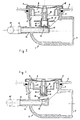
- Figures 1 and 2 are schematical cross-sectional views of a preferred embodiment of the present invention, in respective operating positions thereof.
- With reference to the above Figures, the intake mouth according to the present invention can be noticed to mainly comprise a hollow body 1 provided with at least an
inlet opening 2, which is adapted to communicate with the interior of a whirlpool-type bathtub 4, and at least anoutlet opening 3 which is adapted to be connected to the suction side of at least a recirculation pump. The latter is not shown for reasons of greater simplicity of the description and shall be understood as being associated, in a per se known manner, to a water recriculating circuit comprising also water jet spray nozzles as required to produce the swirling, massaging action of the bath, for instance of the type described in EP-A-0 560 097. - In particular, the
opening 2 of the hollow body is provided in correspondence of a threaded abutment 5 on which a threaded ring-nut 6 can be screwed so as to clamp between such two elements the edge of a corresponding assembly aperture provided in thetub 4. - After the intake mouth is so assembled, the front side of the ring-
nut 6, which defines with a peripheral wall 9 aninlet 8 of the same intake mouth, communicates with the interior of the bathtub through a perforated grille 7 which is preferably screwed on to the ring-nut 6 in correspondence of acentral stem 18 protruding towards the interior of the body 1. - Axially slidable on said
stem 18 there is arranged a movingmember 10 which is provided with at least a discoidal pan 11, or any other similar hydraulically operated sensor means, preferably integral therewith, ie. in a single-piece construction. Furthermore, the movingmember 10 carries, preferably in correspondence of a rear free end portion thereof, at least a shutter means 12. The latter may be of any appropriate type for the given purpose, but is preferably of the elastic membrane type in the shape of a suction cup. - The intake mouth also comprises a
vent pipe 13, which is preferably made integral with the hollow body 1. On one side, such a vent pipe extends outwardly with atubing 14 extending upwards; on the other side, it on the contrary extends into the hollow body 1 in a position which is contiguous to thestem 18. - In particular, the
tubing 14 has afree end portion 15 that communicates with the outside ambient and is arranged above the highest allowable water level inside thetub 4. - On the opposite side, the
vent pipe 13 is adapted to communicate with the interior of the body 1, and therefore with the suction side of the recirculation pump, through at least acalibrated opening 16 that is axially aligned with thestem 18. - A calibrated
thrust member 17 is adapted to normally keep the movingmember 10 in a first operating position thereof, which is axially spaced from theopening 16 as illustrated in Figure 1 and in which the shutter means 12 is disengaged from thecalibrated opening 16 and the pan 11 at least partially shuts theinlet 8 of the intake mouth. - The
thrust member 17 is preferably formed by a compression spring which is partially inserted around the movingmember 10 and an end portion of which is arranged to abut against the pan 11, while the opposite end portion thereof rests in aseat 19 provided on the outside of thepipe 13 around thecalibrated opening 16. - As this will be described in greater detail further on, the moving
member 10 is adapted to move into a second operating position thereof, illustrated in Figure 2, in which the shutter means 12 substantially shuts thecalibrated opening 16, while the pan 11 substantially opens theinlet 8 of the intake mouth. - Under resting conditions (Figure 1), the recirculating pump is inactive. Under these conditions, the
thrust spring 17 keeps the movingmember 10 in an axial position in which the shutter means 12 is disengaged from the opening 16 of thevent pipe 13. It should be noticed that the latter, along with thetubing 14 associated therewith, can substantially fill up with water, owing to the effect of communicating vessels, when the tub 4is filled with water up to a pre-determined level, in a per sè known manner. - When the recirculating pump is started so as to supply the water jet spouts of the bathtub (not shown), and thereby bringing about the swirling massage action of the bath itself, a negative pressure occurs at the
outlet 3 of the body 1 which attracts the pan 11, and therefore the whole movingmember 10, in such a manner as to move it axially away from theinlet 8. Such a displacement occurs, by overcoming the force of thespring 17, so as to enable the water contained in thetub 4 to flow into the body 1 at an appropriate rate. through theopen inlet 8, towards the suction side of the pump. During an initial transient phase, also the water that may possibly be contained in thevent pipe 13 and thetubing 14 is slowly taken in by the pump through thecalibrated opening 16, in such a manner as to prevent the correct priming of same pump from being substantially altered. - The intake mouth switches in this way into the operating state illustrated in Figure 2, in which the moving
member 10 causes the shutter means 12 to shut thecalibrated opening 16. - The intake mouth can therefore operate normally so as to enable a substantial flow of water to take place from the
tub 4 to the recirculating pump through the (open)inlet 8 and theoutlet 3. - Through a proper sizing of the various component parts (which is well within the usual capability of thos skilled in the art), the intake mouth will be arranged so as to be able to operate and respond in the manner described below, so as to maintain constant safe operating conditions, in the case that foreign matters (eg. the hair of a person taking a bath) would adhere to the screening grille 7, thereby reducing the water flow cross-section area towards the
inlet 8 correspondingly. - When the water flow toward the
inlet 8 descends below a pre-determined threshold value (corresponding to a condition of substantial clogging of the grille 7), it is no longer able to exert on the pan 11 a sufficient thrust as required to overcome the force of thespring 17, which therefore causes the movingmember 10 to be displaced towards the resting position illustrated in Figure 1. Thecalibrated opening 16 is thereby opened and communicates with theoutlet 3, which takes in ambient air through the venting arrangement 13-16. In a per se known manner, this leads to a condition in which the recirculating pump becomes substantially unprimed, ie. deactivated. This of course facilitates the separation and the removal of the foreign matters from the grille 7, so as to restore normal operating conditions. - Further to the simplicity in the construction and operation of the intake mouth according to the present invention, from the above description it clearly emerges that such an intake mouth actually ensures full operational reliability and safety, since the recirculation pump is unprimed, ie. deactivated, automatically whenever a dangerous clogging condition occurs in any portion or zone of the grille 7. In an advantageous manner, in fact, the displacements of the moving
member 10 are not controlled by a partial flow of water passing through a localized area of the grille 7, but rather by the variations in the total flow of water passing through the whole cross-section area of the same grille. - It will of course be appreciated that the above described intake mouth may undergo a number of modifications without departing from the scope of the present invention as defined in the appended claims.
Claims (4)
- Intake mouth for whirlpool-type or similar bathtubs, comprising at least an inlet (8) for a water flow towards at least an outlet (3) adapted to be connected to the suction side of pump means, vent means (13-16) being adapted to connect the interior of said intake mouth with the outside ambient, characterized in that it further comprises shutter means (12) capable of being switched from a normal resting position, in which said outlet (3) communicates with said vent means (13-16), into a normal operating condition when said flow of water is caused to move towards said outlet (3), wherein the shutter means (12) substantially shut said vent means (16), said shutter means (12) being adapted to switch from said operating condition into said resting position thereof when said flow of water descends below a pre-determined threshold value, so as to enable air to penetrate the intake mouth (1) through said vent means (13-16) and cut off said flow.
- Intake mouth according to claim 1, characterized in that said shutter means (12) are provided on a moving member (10) which is biased by spring means (17) towards said resting position and also comprises sensor means (11) adapted to be actuated by said flow of water against the force of said spring means so as to displace the moving member (10) into said normal operating position.
- Intake mouth according to claim 2, characterized in that said shutter means comprise an elastic membrane (12) adapted to shut at least a calibrated opening (16) provided in said vent means inside the intake mouth (1).
- Intake mouth according to claim 2, characterized in that said sensor means comprise at least a pan-like member (11) adapted to substantially shut said inlet (8) of the intake mouth when the moving member (10) is in its resting position.
Applications Claiming Priority (2)
| Application Number | Priority Date | Filing Date | Title |
|---|---|---|---|
| ITPN970052 | 1997-09-25 | ||
| IT97PN000052A IT1296329B1 (en) | 1997-09-25 | 1997-09-25 | SUCTION NOZZLE FOR WHIRLPOOL BATHS OR SIMILAR |
Publications (3)
| Publication Number | Publication Date |
|---|---|
| EP0904762A2 EP0904762A2 (en) | 1999-03-31 |
| EP0904762A3 EP0904762A3 (en) | 1999-08-04 |
| EP0904762B1 true EP0904762B1 (en) | 2003-03-12 |
Family
ID=11395300
Family Applications (1)
| Application Number | Title | Priority Date | Filing Date |
|---|---|---|---|
| EP98115666A Expired - Lifetime EP0904762B1 (en) | 1997-09-25 | 1998-08-20 | Intake mouth for whirlpool-type and similar bathtubs |
Country Status (6)
| Country | Link |
|---|---|
| US (1) | US6098648A (en) |
| EP (1) | EP0904762B1 (en) |
| AT (1) | ATE234064T1 (en) |
| DE (1) | DE69812018T2 (en) |
| ES (1) | ES2193449T3 (en) |
| IT (1) | IT1296329B1 (en) |
Families Citing this family (10)
| Publication number | Priority date | Publication date | Assignee | Title |
|---|---|---|---|---|
| US6251285B1 (en) * | 1998-09-17 | 2001-06-26 | Michael James Ciochetti | Method for preventing an obstruction from being trapped by suction to an inlet of a pool filter pump system, and lint trap cover therefor |
| US6374854B1 (en) * | 2000-07-29 | 2002-04-23 | Enrique Acosta | Device for preventing permanent entrapment |
| US7452091B2 (en) * | 2004-10-22 | 2008-11-18 | Itt Manufacturing Enterprises, Inc. | Searchlight featuring bayonet mounting system with 2-speed joystick rotational operation |
| GB2438224A (en) * | 2006-05-17 | 2007-11-21 | Plamen Spassov Vassilev | Automatic Bathtub Filler and Circulation system |
| US7931447B2 (en) * | 2006-06-29 | 2011-04-26 | Hayward Industries, Inc. | Drain safety and pump control device |
| WO2011106530A1 (en) | 2010-02-25 | 2011-09-01 | Hayward Industries, Inc. | Universal mount for a variable speed pump drive user interface |
| AU2014228186B2 (en) | 2013-03-15 | 2019-11-07 | Hayward Industries, Inc. | Modular pool/spa control system |
| US11720085B2 (en) | 2016-01-22 | 2023-08-08 | Hayward Industries, Inc. | Systems and methods for providing network connectivity and remote monitoring, optimization, and control of pool/spa equipment |
| US20170212536A1 (en) | 2016-01-22 | 2017-07-27 | Hayward Industries, Inc. | Systems and Methods for Providing Network Connectivity and Remote Monitoring, Optimization, and Control of Pool/Spa Equipment |
| US10718337B2 (en) | 2016-09-22 | 2020-07-21 | Hayward Industries, Inc. | Self-priming dedicated water feature pump |
Family Cites Families (9)
| Publication number | Priority date | Publication date | Assignee | Title |
|---|---|---|---|---|
| US3556124A (en) * | 1968-08-21 | 1971-01-19 | W F Products Corp | Valve for instant hot water system |
| US4596656A (en) * | 1984-06-13 | 1986-06-24 | Jope Manufacturing Co. Inc. | Hydrotherapy water return fitting for tubs and spas |
| US4643217A (en) * | 1985-05-24 | 1987-02-17 | Arneson Products, Inc. | Automatic valve for use with pool cleaning devices |
| US4602391A (en) * | 1985-10-17 | 1986-07-29 | Pearl Baths Inc. | Dynamically balanced suction relief for hydrotherapy tubs and spas |
| US5347664A (en) * | 1990-06-20 | 1994-09-20 | Kdi American Products, Inc. | Suction fitting with pump control device |
| IT229030Y1 (en) | 1992-03-10 | 1998-06-24 | Albatros System Spa | SPOUT FOR HYDROMASSAGE |
| DE4320639C1 (en) * | 1993-06-22 | 1994-10-13 | Kaldewei Franz Gmbh & Co | Whirlpool bath tub |
| US5499406A (en) * | 1994-12-12 | 1996-03-19 | Hydrabaths, Inc. | Safety suction assembly for use in whirlpool baths and the like |
| US5682624A (en) * | 1995-06-07 | 1997-11-04 | Ciochetti; Michael James | Vacuum relief safety valve for a swimming pool filter pump system |
-
1997
- 1997-09-25 IT IT97PN000052A patent/IT1296329B1/en active IP Right Grant
-
1998
- 1998-08-20 DE DE69812018T patent/DE69812018T2/en not_active Expired - Lifetime
- 1998-08-20 ES ES98115666T patent/ES2193449T3/en not_active Expired - Lifetime
- 1998-08-20 EP EP98115666A patent/EP0904762B1/en not_active Expired - Lifetime
- 1998-08-20 AT AT98115666T patent/ATE234064T1/en not_active IP Right Cessation
- 1998-09-25 US US09/160,800 patent/US6098648A/en not_active Expired - Fee Related
Also Published As
| Publication number | Publication date |
|---|---|
| DE69812018D1 (en) | 2003-04-17 |
| ES2193449T3 (en) | 2003-11-01 |
| IT1296329B1 (en) | 1999-06-25 |
| DE69812018T2 (en) | 2003-10-02 |
| EP0904762A2 (en) | 1999-03-31 |
| EP0904762A3 (en) | 1999-08-04 |
| US6098648A (en) | 2000-08-08 |
| ITPN970052A1 (en) | 1999-03-25 |
| ATE234064T1 (en) | 2003-03-15 |
Similar Documents
| Publication | Publication Date | Title |
|---|---|---|
| US6003165A (en) | Portable spa with safety suction shut-off | |
| EP0904762B1 (en) | Intake mouth for whirlpool-type and similar bathtubs | |
| US5347664A (en) | Suction fitting with pump control device | |
| US6895608B2 (en) | Hydraulic suction fuse for swimming pools | |
| WO1996018335A1 (en) | Whirlpool bath safety suction assembly | |
| CA2015958C (en) | Coffee or tea machine | |
| CA2292969A1 (en) | A water catchment device floating at the surface of a basin ans supplying a pumping system | |
| US20010002596A1 (en) | Liquid circuit reservoir | |
| US4286342A (en) | Toilet installation | |
| JP2023050073A (en) | Liquid heating vessel | |
| EP0730857B1 (en) | Suction nozzle for hydromassage | |
| US4132936A (en) | Condensate discharge apparatus | |
| KR100327843B1 (en) | Pump for fluid | |
| JP3349035B2 (en) | Defoaming device for horizontal drain pipe | |
| CN114013798B (en) | Tea capsule | |
| EP0797973B1 (en) | Valve for venting the air from the intake pipe of an intake orificie for hydro-massage | |
| KR102223924B1 (en) | water purifier | |
| JP3085521B2 (en) | Pump-filled electric hot water storage container | |
| JP2001052578A (en) | Float switch, hot-water tank and hot-water cleaning device | |
| JP6916080B2 (en) | Submersible pump device | |
| JPH10151308A (en) | Circulating purifier | |
| JP3476275B2 (en) | Bubble tub with protective device | |
| CA2048109A1 (en) | Anti-flooding bypass for an electrical cabinet | |
| JPH0735923B2 (en) | Backflow prevention device for water heater with bath reheating oven | |
| JPH09253147A (en) | Circulating pump mechanism for bathtub |
Legal Events
| Date | Code | Title | Description |
|---|---|---|---|
| PUAI | Public reference made under article 153(3) epc to a published international application that has entered the european phase |
Free format text: ORIGINAL CODE: 0009012 |
|
| AK | Designated contracting states |
Kind code of ref document: A2 Designated state(s): AT DE ES FR GB IT Kind code of ref document: A2 Designated state(s): AT CH DE ES FR GB IT LI |
|
| AX | Request for extension of the european patent |
Free format text: AL;LT;LV;MK;RO;SI |
|
| PUAL | Search report despatched |
Free format text: ORIGINAL CODE: 0009013 |
|
| AK | Designated contracting states |
Kind code of ref document: A3 Designated state(s): AT BE CH CY DE DK ES FI FR GB GR IE IT LI LU MC NL PT SE |
|
| AX | Request for extension of the european patent |
Free format text: AL;LT;LV;MK;RO;SI |
|
| 17P | Request for examination filed |
Effective date: 19991223 |
|
| AKX | Designation fees paid |
Free format text: AT DE ES FR GB IT |
|
| GRAH | Despatch of communication of intention to grant a patent |
Free format text: ORIGINAL CODE: EPIDOS IGRA |
|
| RBV | Designated contracting states (corrected) |
Designated state(s): AT CH DE ES FR GB IT LI |
|
| GRAH | Despatch of communication of intention to grant a patent |
Free format text: ORIGINAL CODE: EPIDOS IGRA |
|
| GRAA | (expected) grant |
Free format text: ORIGINAL CODE: 0009210 |
|
| AK | Designated contracting states |
Designated state(s): AT CH DE ES FR GB IT LI |
|
| REG | Reference to a national code |
Ref country code: GB Ref legal event code: FG4D |
|
| REG | Reference to a national code |
Ref country code: CH Ref legal event code: EP |
|
| REG | Reference to a national code |
Ref country code: CH Ref legal event code: NV Representative=s name: PATENTANWAELTE SCHAAD, BALASS, MENZL & PARTNER AG |
|
| REF | Corresponds to: |
Ref document number: 69812018 Country of ref document: DE Date of ref document: 20030417 Kind code of ref document: P |
|
| ET | Fr: translation filed | ||
| REG | Reference to a national code |
Ref country code: ES Ref legal event code: FG2A Ref document number: 2193449 Country of ref document: ES Kind code of ref document: T3 |
|
| PLBE | No opposition filed within time limit |
Free format text: ORIGINAL CODE: 0009261 |
|
| STAA | Information on the status of an ep patent application or granted ep patent |
Free format text: STATUS: NO OPPOSITION FILED WITHIN TIME LIMIT |
|
| 26N | No opposition filed |
Effective date: 20031215 |
|
| REG | Reference to a national code |
Ref country code: CH Ref legal event code: PUE Owner name: WELLNESS EUROPE S.R.L. Free format text: DOMINO S.P.A.#VIA VALCELLINA, ZONA INDUSTRIALE NORD#33097 SPILIMBERGO, PORDENONE (IT) -TRANSFER TO- WELLNESS EUROPE S.R.L.#VIA VALCELLINA 2 ZONA INDUSTRIALE NORD#33097 SPILIMBERGO (IT) Ref country code: CH Ref legal event code: PFA Owner name: DOMINO S.R.L. Free format text: WELLNESS EUROPE S.R.L.#VIA VALCELLINA 2 ZONA INDUSTRIALE NORD#33097 SPILIMBERGO (IT) -TRANSFER TO- DOMINO S.R.L.#VIA VALCELLINA 2 ZONA INDUSTRIALE NORD#33097 SPILIMBERGO (IT) |
|
| REG | Reference to a national code |
Ref country code: CH Ref legal event code: NV Representative=s name: PATENTANWAELTE SCHAAD, BALASS, MENZL & PARTNER AG |
|
| REG | Reference to a national code |
Ref country code: GB Ref legal event code: 732E |
|
| REG | Reference to a national code |
Ref country code: FR Ref legal event code: TP Ref country code: FR Ref legal event code: CD |
|
| REG | Reference to a national code |
Ref country code: GB Ref legal event code: 732E |
|
| REG | Reference to a national code |
Ref country code: FR Ref legal event code: GC |
|
| PGFP | Annual fee paid to national office [announced via postgrant information from national office to epo] |
Ref country code: AT Payment date: 20060705 Year of fee payment: 9 |
|
| PGFP | Annual fee paid to national office [announced via postgrant information from national office to epo] |
Ref country code: ES Payment date: 20060807 Year of fee payment: 9 |
|
| PG25 | Lapsed in a contracting state [announced via postgrant information from national office to epo] |
Ref country code: AT Free format text: LAPSE BECAUSE OF NON-PAYMENT OF DUE FEES Effective date: 20070820 |
|
| REG | Reference to a national code |
Ref country code: ES Ref legal event code: FD2A Effective date: 20070821 |
|
| PG25 | Lapsed in a contracting state [announced via postgrant information from national office to epo] |
Ref country code: ES Free format text: LAPSE BECAUSE OF NON-PAYMENT OF DUE FEES Effective date: 20070821 |
|
| REG | Reference to a national code |
Ref country code: GB Ref legal event code: 732E Free format text: REGISTERED BETWEEN 20100128 AND 20100203 |
|
| PGFP | Annual fee paid to national office [announced via postgrant information from national office to epo] |
Ref country code: CH Payment date: 20110824 Year of fee payment: 14 |
|
| PGFP | Annual fee paid to national office [announced via postgrant information from national office to epo] |
Ref country code: GB Payment date: 20110819 Year of fee payment: 14 Ref country code: DE Payment date: 20110823 Year of fee payment: 14 Ref country code: FR Payment date: 20110901 Year of fee payment: 14 |
|
| PGFP | Annual fee paid to national office [announced via postgrant information from national office to epo] |
Ref country code: IT Payment date: 20110809 Year of fee payment: 14 |
|
| REG | Reference to a national code |
Ref country code: CH Ref legal event code: PL |
|
| GBPC | Gb: european patent ceased through non-payment of renewal fee |
Effective date: 20120820 |
|
| PG25 | Lapsed in a contracting state [announced via postgrant information from national office to epo] |
Ref country code: LI Free format text: LAPSE BECAUSE OF NON-PAYMENT OF DUE FEES Effective date: 20120831 Ref country code: CH Free format text: LAPSE BECAUSE OF NON-PAYMENT OF DUE FEES Effective date: 20120831 |
|
| REG | Reference to a national code |
Ref country code: FR Ref legal event code: ST Effective date: 20130430 |
|
| PG25 | Lapsed in a contracting state [announced via postgrant information from national office to epo] |
Ref country code: IT Free format text: LAPSE BECAUSE OF NON-PAYMENT OF DUE FEES Effective date: 20120820 |
|
| PG25 | Lapsed in a contracting state [announced via postgrant information from national office to epo] |
Ref country code: GB Free format text: LAPSE BECAUSE OF NON-PAYMENT OF DUE FEES Effective date: 20120820 Ref country code: DE Free format text: LAPSE BECAUSE OF NON-PAYMENT OF DUE FEES Effective date: 20130301 |
|
| PG25 | Lapsed in a contracting state [announced via postgrant information from national office to epo] |
Ref country code: FR Free format text: LAPSE BECAUSE OF NON-PAYMENT OF DUE FEES Effective date: 20120831 |
|
| REG | Reference to a national code |
Ref country code: DE Ref legal event code: R119 Ref document number: 69812018 Country of ref document: DE Effective date: 20130301 |