EP0904733A1 - A method and apparatus for recording a three-dimensional image of a body part - Google Patents
A method and apparatus for recording a three-dimensional image of a body part Download PDFInfo
- Publication number
- EP0904733A1 EP0904733A1 EP97116843A EP97116843A EP0904733A1 EP 0904733 A1 EP0904733 A1 EP 0904733A1 EP 97116843 A EP97116843 A EP 97116843A EP 97116843 A EP97116843 A EP 97116843A EP 0904733 A1 EP0904733 A1 EP 0904733A1
- Authority
- EP
- European Patent Office
- Prior art keywords
- detector
- patient
- tomograph
- dimensional image
- reference device
- Prior art date
- Legal status (The legal status is an assumption and is not a legal conclusion. Google has not performed a legal analysis and makes no representation as to the accuracy of the status listed.)
- Granted
Links
Images
Classifications
-
- A—HUMAN NECESSITIES
- A61—MEDICAL OR VETERINARY SCIENCE; HYGIENE
- A61B—DIAGNOSIS; SURGERY; IDENTIFICATION
- A61B6/00—Apparatus or devices for radiation diagnosis; Apparatus or devices for radiation diagnosis combined with radiation therapy equipment
- A61B6/52—Devices using data or image processing specially adapted for radiation diagnosis
- A61B6/5258—Devices using data or image processing specially adapted for radiation diagnosis involving detection or reduction of artifacts or noise
- A61B6/5264—Devices using data or image processing specially adapted for radiation diagnosis involving detection or reduction of artifacts or noise due to motion
- A61B6/527—Devices using data or image processing specially adapted for radiation diagnosis involving detection or reduction of artifacts or noise due to motion using data from a motion artifact sensor
-
- A—HUMAN NECESSITIES
- A61—MEDICAL OR VETERINARY SCIENCE; HYGIENE
- A61B—DIAGNOSIS; SURGERY; IDENTIFICATION
- A61B5/00—Measuring for diagnostic purposes; Identification of persons
- A61B5/103—Measuring devices for testing the shape, pattern, colour, size or movement of the body or parts thereof, for diagnostic purposes
- A61B5/11—Measuring movement of the entire body or parts thereof, e.g. head or hand tremor or mobility of a limb
- A61B5/1113—Local tracking of patients, e.g. in a hospital or private home
- A61B5/1114—Tracking parts of the body
-
- A—HUMAN NECESSITIES
- A61—MEDICAL OR VETERINARY SCIENCE; HYGIENE
- A61B—DIAGNOSIS; SURGERY; IDENTIFICATION
- A61B5/00—Measuring for diagnostic purposes; Identification of persons
- A61B5/103—Measuring devices for testing the shape, pattern, colour, size or movement of the body or parts thereof, for diagnostic purposes
- A61B5/11—Measuring movement of the entire body or parts thereof, e.g. head or hand tremor or mobility of a limb
- A61B5/1126—Measuring movement of the entire body or parts thereof, e.g. head or hand tremor or mobility of a limb using a particular sensing technique
- A61B5/1127—Measuring movement of the entire body or parts thereof, e.g. head or hand tremor or mobility of a limb using a particular sensing technique using markers
-
- A—HUMAN NECESSITIES
- A61—MEDICAL OR VETERINARY SCIENCE; HYGIENE
- A61B—DIAGNOSIS; SURGERY; IDENTIFICATION
- A61B5/00—Measuring for diagnostic purposes; Identification of persons
- A61B5/72—Signal processing specially adapted for physiological signals or for diagnostic purposes
- A61B5/7203—Signal processing specially adapted for physiological signals or for diagnostic purposes for noise prevention, reduction or removal
- A61B5/7207—Signal processing specially adapted for physiological signals or for diagnostic purposes for noise prevention, reduction or removal of noise induced by motion artifacts
- A61B5/721—Signal processing specially adapted for physiological signals or for diagnostic purposes for noise prevention, reduction or removal of noise induced by motion artifacts using a separate sensor to detect motion or using motion information derived from signals other than the physiological signal to be measured
-
- A—HUMAN NECESSITIES
- A61—MEDICAL OR VETERINARY SCIENCE; HYGIENE
- A61B—DIAGNOSIS; SURGERY; IDENTIFICATION
- A61B6/00—Apparatus or devices for radiation diagnosis; Apparatus or devices for radiation diagnosis combined with radiation therapy equipment
- A61B6/08—Auxiliary means for directing the radiation beam to a particular spot, e.g. using light beams
-
- A—HUMAN NECESSITIES
- A61—MEDICAL OR VETERINARY SCIENCE; HYGIENE
- A61B—DIAGNOSIS; SURGERY; IDENTIFICATION
- A61B90/00—Instruments, implements or accessories specially adapted for surgery or diagnosis and not covered by any of the groups A61B1/00 - A61B50/00, e.g. for luxation treatment or for protecting wound edges
- A61B90/10—Instruments, implements or accessories specially adapted for surgery or diagnosis and not covered by any of the groups A61B1/00 - A61B50/00, e.g. for luxation treatment or for protecting wound edges for stereotaxic surgery, e.g. frame-based stereotaxis
- A61B90/14—Fixators for body parts, e.g. skull clamps; Constructional details of fixators, e.g. pins
- A61B90/16—Bite blocks
-
- A—HUMAN NECESSITIES
- A61—MEDICAL OR VETERINARY SCIENCE; HYGIENE
- A61B—DIAGNOSIS; SURGERY; IDENTIFICATION
- A61B34/00—Computer-aided surgery; Manipulators or robots specially adapted for use in surgery
- A61B34/20—Surgical navigation systems; Devices for tracking or guiding surgical instruments, e.g. for frameless stereotaxis
- A61B2034/2046—Tracking techniques
- A61B2034/2055—Optical tracking systems
-
- A—HUMAN NECESSITIES
- A61—MEDICAL OR VETERINARY SCIENCE; HYGIENE
- A61B—DIAGNOSIS; SURGERY; IDENTIFICATION
- A61B34/00—Computer-aided surgery; Manipulators or robots specially adapted for use in surgery
- A61B34/20—Surgical navigation systems; Devices for tracking or guiding surgical instruments, e.g. for frameless stereotaxis
- A61B2034/2072—Reference field transducer attached to an instrument or patient
-
- A—HUMAN NECESSITIES
- A61—MEDICAL OR VETERINARY SCIENCE; HYGIENE
- A61B—DIAGNOSIS; SURGERY; IDENTIFICATION
- A61B90/00—Instruments, implements or accessories specially adapted for surgery or diagnosis and not covered by any of the groups A61B1/00 - A61B50/00, e.g. for luxation treatment or for protecting wound edges
- A61B90/36—Image-producing devices or illumination devices not otherwise provided for
- A61B2090/363—Use of fiducial points
-
- A—HUMAN NECESSITIES
- A61—MEDICAL OR VETERINARY SCIENCE; HYGIENE
- A61B—DIAGNOSIS; SURGERY; IDENTIFICATION
- A61B90/00—Instruments, implements or accessories specially adapted for surgery or diagnosis and not covered by any of the groups A61B1/00 - A61B50/00, e.g. for luxation treatment or for protecting wound edges
- A61B90/36—Image-producing devices or illumination devices not otherwise provided for
- A61B2090/364—Correlation of different images or relation of image positions in respect to the body
- A61B2090/367—Correlation of different images or relation of image positions in respect to the body creating a 3D dataset from 2D images using position information
-
- A—HUMAN NECESSITIES
- A61—MEDICAL OR VETERINARY SCIENCE; HYGIENE
- A61B—DIAGNOSIS; SURGERY; IDENTIFICATION
- A61B90/00—Instruments, implements or accessories specially adapted for surgery or diagnosis and not covered by any of the groups A61B1/00 - A61B50/00, e.g. for luxation treatment or for protecting wound edges
- A61B90/36—Image-producing devices or illumination devices not otherwise provided for
- A61B90/37—Surgical systems with images on a monitor during operation
- A61B2090/376—Surgical systems with images on a monitor during operation using X-rays, e.g. fluoroscopy
- A61B2090/3762—Surgical systems with images on a monitor during operation using X-rays, e.g. fluoroscopy using computed tomography systems [CT]
-
- A—HUMAN NECESSITIES
- A61—MEDICAL OR VETERINARY SCIENCE; HYGIENE
- A61B—DIAGNOSIS; SURGERY; IDENTIFICATION
- A61B90/00—Instruments, implements or accessories specially adapted for surgery or diagnosis and not covered by any of the groups A61B1/00 - A61B50/00, e.g. for luxation treatment or for protecting wound edges
- A61B90/39—Markers, e.g. radio-opaque or breast lesions markers
- A61B2090/3937—Visible markers
- A61B2090/3945—Active visible markers, e.g. light emitting diodes
-
- A—HUMAN NECESSITIES
- A61—MEDICAL OR VETERINARY SCIENCE; HYGIENE
- A61B—DIAGNOSIS; SURGERY; IDENTIFICATION
- A61B90/00—Instruments, implements or accessories specially adapted for surgery or diagnosis and not covered by any of the groups A61B1/00 - A61B50/00, e.g. for luxation treatment or for protecting wound edges
- A61B90/39—Markers, e.g. radio-opaque or breast lesions markers
- A61B2090/3995—Multi-modality markers
-
- A—HUMAN NECESSITIES
- A61—MEDICAL OR VETERINARY SCIENCE; HYGIENE
- A61B—DIAGNOSIS; SURGERY; IDENTIFICATION
- A61B2562/00—Details of sensors; Constructional details of sensor housings or probes; Accessories for sensors
- A61B2562/04—Arrangements of multiple sensors of the same type
- A61B2562/043—Arrangements of multiple sensors of the same type in a linear array
-
- A—HUMAN NECESSITIES
- A61—MEDICAL OR VETERINARY SCIENCE; HYGIENE
- A61B—DIAGNOSIS; SURGERY; IDENTIFICATION
- A61B34/00—Computer-aided surgery; Manipulators or robots specially adapted for use in surgery
- A61B34/20—Surgical navigation systems; Devices for tracking or guiding surgical instruments, e.g. for frameless stereotaxis
Definitions
- the invention relates to a method and an apparatus for recording a three dimensional image of a part of a patient's body according to the preamble of the independent claims as well as to a reference device for being mounted to a patient's head while using such a method.
- Three dimensional images of this type are usually generated from a plurality of planar scans and information describing the spatial relation between these scans and/or between the patient and the scans.
- Known methods are e.g. based on the principles of computer tomography, NMR tomography, ultransonic analysis, positron emission tomography or X-ray techniques.
- a body part such as a patient's head
- immobilization of the position of a body part is usually difficult and/or uncomfortable for the patient due to invasive attachments of head rings or frames.
- the movements or positional changes are detected optically, e.g. by affixing reference markers to the body part, which are observed by a camera system.
- an optical position detection is preferred for its simplicity and high immunity to noise.
- a reference device with suited reference marks is mounted to the body part to be measured.
- the reference device should be attached to at least one tooth of the patient's upper jaw. Further connections between the head and the reference device are not necessary.
- the reference device can be affixed to upper jaw by conventional dental impression material or by other means of fixation, such as clamps or dental prostheses for toothless patients.
- the reference device comprises a mouthpiece, which is non-invasively connected to the upper jaw in the manner described above, as well as a reference member attachable to the mouth piece for being detected by the positional detector.
- the reference member can be titled in respect to the mouthpiece, which allows to establish an optimum orientation for each recording geometry.
- the relation of the reference markers (i.e. the coordinate system of the positional detector) in respect to the body part (i.e. the coordinate system of the three-dimensional image or the coordinate system of the imaging system) are stored together with the image. This makes it possible to position the patient later by means of the reference markers.
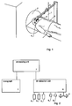
- Figure 1 shows an application of the invention in a computer tomograph 1.
- Computer tomograph 1 comprises a measuring zone 2 for receiving the head of the patient 3.
- the patient 3 carries a reference device 4 in his/her mouth, the three-dimensional position of which is monitored during the whole image acquisition process by means of three cameras 5.
- the three cameras 5 are connected to a 3-D detection unit 6.
- Tomograph 1 and 3-D detection unit 6 are connected to a processing unit 7, which assembles the scans from the tomograph into a three dimensional image.
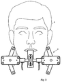
- reference device 4 consists of a mouth piece 10 and a reference member 11.
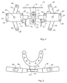
- the mouth piece 10 comprises a U-shaped bite-down plate 12 connected to an L-shaped arm 13.
- a attachment bracket 14 is connected to arm 13 by means of two screws 15.
- Bracket 14 carries a rod 16 of reference member 11.
- Rod 16 is rotatably held in bracket 14 and can be fixed against rotation by means of two screws 17. This provides the possibility to use any scanning plane of the imaging system, such as coronal or sagittal scanning.
- Two lateral bodies 18 are arranged at the ends of rod 16, each carrying two fingers 19.
- infrared diodes are mounted to the lateral bodies 18 and the fingers 19. They are used as reference markers and their position can be measured by the cameras 5 and the 3-D detection unit 6.
- the diodes 20 are connected to 3-D detection unit 6 by means of cables 21 and are driven in multiplexed operation.
- the lateral bodies 18 are slightly inclined in respect to rod 16 such that not all of the diodes are arranged in the same plane. This increases the accuracy of the measured position of reference device 4.
- Reference points 23 consisting of a material that can be detected by tomograph 1 are attached to the lateral bodies 18. Different positions are used to arrange the reference points 23 and the diodes 20 on the lateral bodies. The function of the reference points 23 is described below.
- the apparatus works as follows:
- bite-down plate 12 is embedded in rapidly settling dental impression material and introduced into the patient's mouth. The patient bites bite-down plate 12 until the material is hardened. This provides a substantially rigid connection between reference device 4 and the teeth of the patient's upper jaw and thereby between reference device 4 and the patient's skull. A further connection between the reference device and the patient's head is not required.
- rod 16 is positioned in bracket 14 in a position where the diodes 20 can be detected by the cameras 5 during the whole tomographic measurement. At least three diodes should be visible. Then rod 16 is fastened by means of the screws 15.
- tomograph 1 a plurality of conventionally scanned sectional images are acquired. For each scanned image, the position of the diodes and thereby the three dimensional orientation of reference device 4 relative to the camera system is measured.
- the positions of both lateral bodies 18 can be measured independently for detecting a relative movement of the lateral bodies 18 and thereby a deformation of the geometry of reference device 4.
- the movement of the table carrying the patient can be determined by infrared diodes 8 (Fig. 2).
- At least one image is acquired showing at least three or more of the reference points 23.
- the information stored under point 2 allows 3-D processing unit 7 to assemble the sectional images into a high quality and precise three dimensional image taking account of the patient's head movements.
- the three dimensional image is stored together with information describing the relative position of reference device 4 in respect to the three dimensional image (i.e. indicating the relative position of reference device 4 in respect to the patient's head).
- reference device 4 After the measurement, reference device 4 is removed from the patient's teeth. However, as long as the hardened impression material remains on the bite-down plate, the reference device can always be attached in the same position on the teeth of the patient's upper jaw. Since information indicating the relative position of reference device 4 in respect to the coordinate system of the 3-D image has been stored together with the 3-D image, the position of the patient's head can immediately be determined when the reference device is reattached. This can e.g. be used when the patient has to undergo surgical treatment several days after image data acquisition. The reference device is again inserted into the patient's mouth and the surgeon's 3-D detection system can determine its position. The same 3-D detection system can e.g. also be used for measuring the position of surgical instruments and for overlaying them with the 3-D image of the patient's head.
- mouth piece 10 and reference member 11 can be separated from each other such that after establishing the tomographic image reference member 11 can be used for other patients.
- the mouth piece adapted to the patient is retained and can be reconnected to the reference member during later surgical treatment.
- the parts are designed such that the relative position between reference member 11 and mouth piece 10 can be re-established accurately.
- the concept described here allows the generation of three-dimensional images having high accuracy while it obviates the need to immobilize the position of the head (or any other body part) during image acquisition and surgical treatment. By means of the continuous measurement of the head position during acquisition, movements of the patient can be compensated for.
- a further set of diodes 9 can be attached to the tomograph for marking the scanning plane and for determination of its position. They can be used for measuring the inclination of the tomograph and/or for determining the relative position between cameras and the tomograph (i.e. the relation between the coordinate systems of the 3-D detection unit and the tomograph).
- reference device 4 can be more compact and e.g. have the shape of a baby's comforter, which is attached to one or more teeth of the upper jaw.
- suitable clamps or other means such as dental prostheses, can be used.
- the position of reference device 4 is determined from the position of the diodes 20. It is conceivable, however, that no active components are arranged on reference device 4 and its position is determined by processing the images from the cameras 5. The position of the head can also be measured directly, without using reference device 4, by recording it using several cameras and calculating its position by image processing.
- Determining the position by optical means is preferred because optical signals do not interfere with the operation of the tomograph. Furthermore, it is fast and e.g. allows to detect a movement during acquiring a single sectional image in a short time interval - if necessary, the scanned image can be corrected in its position and/or be re-scanned.
- the invention is applied for a computer tomograph, but it can also be used in other 3-D imaging techniques of body parts, e.g. in NMR tomography, ultrasound scanning techniques, angiography, positron emission tomography, imaging nuclear medical methods, planar radiography etc.
- the tomograph (the image acquisition device) forms a first detector, which is acquiring single scans during an extended time interval, from which scans the complete three dimensional images can be assembled.
- first detector which is acquiring single scans during an extended time interval, from which scans the complete three dimensional images can be assembled.
- second detector independent of the first detector, is used for continuously measuring and recording the position of the head (or any other body part to be viewed).
- the positional data retrieved in this way are used for correcting (if necessary) the data from the first detector and for generating the three dimensional image.
Landscapes
- Health & Medical Sciences (AREA)
- Life Sciences & Earth Sciences (AREA)
- Engineering & Computer Science (AREA)
- Medical Informatics (AREA)
- Surgery (AREA)
- Public Health (AREA)
- Pathology (AREA)
- Biomedical Technology (AREA)
- Heart & Thoracic Surgery (AREA)
- Molecular Biology (AREA)
- Animal Behavior & Ethology (AREA)
- General Health & Medical Sciences (AREA)
- Veterinary Medicine (AREA)
- Physics & Mathematics (AREA)
- Biophysics (AREA)
- Nuclear Medicine, Radiotherapy & Molecular Imaging (AREA)
- Oral & Maxillofacial Surgery (AREA)
- Physiology (AREA)
- Signal Processing (AREA)
- Dentistry (AREA)
- Computer Vision & Pattern Recognition (AREA)
- High Energy & Nuclear Physics (AREA)
- Optics & Photonics (AREA)
- Radiology & Medical Imaging (AREA)
- Artificial Intelligence (AREA)
- Neurosurgery (AREA)
- Psychiatry (AREA)
- Apparatus For Radiation Diagnosis (AREA)
- Dental Tools And Instruments Or Auxiliary Dental Instruments (AREA)
- Magnetic Resonance Imaging Apparatus (AREA)
- Image Processing (AREA)
- Image Analysis (AREA)
Abstract
Description
- The invention relates to a method and an apparatus for recording a three dimensional image of a part of a patient's body according to the preamble of the independent claims as well as to a reference device for being mounted to a patient's head while using such a method.
- Various methods and devices are known for recording three-dimensional images of a part of a patient's body. Three dimensional images of this type are usually generated from a plurality of planar scans and information describing the spatial relation between these scans and/or between the patient and the scans. Known methods are e.g. based on the principles of computer tomography, NMR tomography, ultransonic analysis, positron emission tomography or X-ray techniques. Especially while recording extended areas it is important that the part of the body is fixed in place because movement may affect the quality of the image. However, immobilization of the position of a body part, such as a patient's head, is usually difficult and/or uncomfortable for the patient due to invasive attachments of head rings or frames.
- It is therefore an object of the present invention to provide a device and a method of the type mentioned above that obviates these disadvantages at least partially.
- This object is met by the independent claims.
- By measuring movements, i.e. positional changes, of the body part during image acquisition, it becomes possible to correct the acquired image data. If the patient e.g. moves (especially turns) during acquisition, the image data are corrected such that all scanned images are transformed to the same coordinate system and can be combined with high accuracy.
- Preferably, the movements or positional changes are detected optically, e.g. by affixing reference markers to the body part, which are observed by a camera system. However, it is also possible to detect the position of the body part directly by means of suited image processing techniques, i.e. without using reference markers. In any case, an optical position detection is preferred for its simplicity and high immunity to noise. But it is also possible to detect movements and positional changes by other means, e.g. ultrasonic triangulation.
- Preferably, a reference device with suited reference marks is mounted to the body part to be measured.
- If the measurement is performed on a patient's head, the reference device should be attached to at least one tooth of the patient's upper jaw. Further connections between the head and the reference device are not necessary. The reference device can be affixed to upper jaw by conventional dental impression material or by other means of fixation, such as clamps or dental prostheses for toothless patients.
- Preferably, the reference device comprises a mouthpiece, which is non-invasively connected to the upper jaw in the manner described above, as well as a reference member attachable to the mouth piece for being detected by the positional detector. The reference member can be titled in respect to the mouthpiece, which allows to establish an optimum orientation for each recording geometry.
- In a preferred embodiment the relation of the reference markers (i.e. the coordinate system of the positional detector) in respect to the body part (i.e. the coordinate system of the three-dimensional image or the coordinate system of the imaging system) are stored together with the image. This makes it possible to position the patient later by means of the reference markers.
- Further advantages, applications and preferred embodiments are described in the dependent claims and the following disclosure of an embodiment with reference to the figures. The figures show:
- Fig. 1 a view of a topographic apparatus according to the present invention,
- Fig. 2 a block diagram of the apparatus of Fig. 1,
- Fig. 3 a reference device according to the invention in the mouth of a patient,
- Fig. 4 the reference device of Fig. 3, and
- Fig. 5 a view of the device of Fig. 4 perpendicular to the mouth piece.
-
- Figure 1 shows an application of the invention in a
computer tomograph 1.Computer tomograph 1 comprises a measuring zone 2 for receiving the head of thepatient 3. As will be described in more detail, thepatient 3 carries areference device 4 in his/her mouth, the three-dimensional position of which is monitored during the whole image acquisition process by means of threecameras 5. - As can be seen from Fig. 2, the three
cameras 5 are connected to a 3-D detection unit 6.Tomograph 1 and 3-D detection unit 6 are connected to aprocessing unit 7, which assembles the scans from the tomograph into a three dimensional image. - As shown in Figs. 3 - 5,
reference device 4 consists of amouth piece 10 and areference member 11. Themouth piece 10 comprises a U-shaped bite-downplate 12 connected to an L-shaped arm 13. Aattachment bracket 14 is connected toarm 13 by means of twoscrews 15. Bracket 14 carries arod 16 ofreference member 11.Rod 16 is rotatably held inbracket 14 and can be fixed against rotation by means of twoscrews 17. This provides the possibility to use any scanning plane of the imaging system, such as coronal or sagittal scanning. Twolateral bodies 18 are arranged at the ends ofrod 16, each carrying twofingers 19. - Fourteen infrared diodes are mounted to the
lateral bodies 18 and thefingers 19. They are used as reference markers and their position can be measured by thecameras 5 and the 3-D detection unit 6. For this purpose, thediodes 20 are connected to 3-D detection unit 6 by means ofcables 21 and are driven in multiplexed operation. - As can be seen from Fig. 5, the
lateral bodies 18 are slightly inclined in respect torod 16 such that not all of the diodes are arranged in the same plane. This increases the accuracy of the measured position ofreference device 4. -
Reference points 23 consisting of a material that can be detected bytomograph 1 are attached to thelateral bodies 18. Different positions are used to arrange thereference points 23 and thediodes 20 on the lateral bodies. The function of thereference points 23 is described below. - The apparatus works as follows:
- Before image data acquisition, bite-down
plate 12 is embedded in rapidly settling dental impression material and introduced into the patient's mouth. The patient bites bite-downplate 12 until the material is hardened. This provides a substantially rigid connection betweenreference device 4 and the teeth of the patient's upper jaw and thereby betweenreference device 4 and the patient's skull. A further connection between the reference device and the patient's head is not required. - Then
rod 16 is positioned inbracket 14 in a position where thediodes 20 can be detected by thecameras 5 during the whole tomographic measurement. At least three diodes should be visible. Thenrod 16 is fastened by means of thescrews 15. - Now the patient is introduced into
tomograph 1 and a plurality of conventionally scanned sectional images are acquired. For each scanned image, the position of the diodes and thereby the three dimensional orientation ofreference device 4 relative to the camera system is measured. - The positions of both
lateral bodies 18 can be measured independently for detecting a relative movement of thelateral bodies 18 and thereby a deformation of the geometry ofreference device 4. - Furthermore, the movement of the table carrying the patient can be determined by infrared diodes 8 (Fig. 2).
- In addition to this, at least one image is acquired showing at least three or more of the
reference points 23. - This provides the following data:
- 1. All scanned images that show the
reference points 23 allow the determination of the position of the scanning plane of the imaging system in respect to the camera system, i.e. the relation of the coordinate system oftomograph 1 in respect to the coordinate system of 3-D detection unit 6. (Alternatively, the position of the scanning plane of the imaging system in respect ot the camera system may also be known from an earlier calibration, in which case thereference points 23 are not required). - 2. As mentioned above, the 3-D position of
reference device 4 is recorded for each sectional image scanned by the tomograph. This makes it possible to calculate all translatory and rotatory movements of the patient in respect to the coordinate system of the tomograph, i.e. the relative position of the patient's head in respect to the tomograph is known. The corresponding information is stored for each scanned image. -
- The information stored under point 2 allows 3-
D processing unit 7 to assemble the sectional images into a high quality and precise three dimensional image taking account of the patient's head movements. - The three dimensional image is stored together with information describing the relative position of
reference device 4 in respect to the three dimensional image (i.e. indicating the relative position ofreference device 4 in respect to the patient's head). - After the measurement,
reference device 4 is removed from the patient's teeth. However, as long as the hardened impression material remains on the bite-down plate, the reference device can always be attached in the same position on the teeth of the patient's upper jaw. Since information indicating the relative position ofreference device 4 in respect to the coordinate system of the 3-D image has been stored together with the 3-D image, the position of the patient's head can immediately be determined when the reference device is reattached. This can e.g. be used when the patient has to undergo surgical treatment several days after image data acquisition. The reference device is again inserted into the patient's mouth and the surgeon's 3-D detection system can determine its position. The same 3-D detection system can e.g. also be used for measuring the position of surgical instruments and for overlaying them with the 3-D image of the patient's head. - Preferably,
mouth piece 10 andreference member 11 can be separated from each other such that after establishing the tomographicimage reference member 11 can be used for other patients. The mouth piece adapted to the patient is retained and can be reconnected to the reference member during later surgical treatment. For this purpose, the parts are designed such that the relative position betweenreference member 11 andmouth piece 10 can be re-established accurately. - The concept described here allows the generation of three-dimensional images having high accuracy while it obviates the need to immobilize the position of the head (or any other body part) during image acquisition and surgical treatment. By means of the continuous measurement of the head position during acquisition, movements of the patient can be compensated for.
- In addition to the infrared diodes mentioned above, a further set of diodes 9 (Fig. 2) can be attached to the tomograph for marking the scanning plane and for determination of its position. They can be used for measuring the inclination of the tomograph and/or for determining the relative position between cameras and the tomograph (i.e. the relation between the coordinate systems of the 3-D detection unit and the tomograph).
- This basic concept can also be embodied using means different from those described so far. For example, it is possible to vary the design of
reference device 4. Depending on desired accuracy of the 3-D detection unit,reference device 4 can be more compact and e.g. have the shape of a baby's comforter, which is attached to one or more teeth of the upper jaw. - Instead of using dental impression material for attaching the reference device, suitable clamps or other means, such as dental prostheses, can be used.
- In the present embodiment, the position of
reference device 4 is determined from the position of thediodes 20. It is conceivable, however, that no active components are arranged onreference device 4 and its position is determined by processing the images from thecameras 5. The position of the head can also be measured directly, without usingreference device 4, by recording it using several cameras and calculating its position by image processing. - Determining the position by optical means is preferred because optical signals do not interfere with the operation of the tomograph. Furthermore, it is fast and e.g. allows to detect a movement during acquiring a single sectional image in a short time interval - if necessary, the scanned image can be corrected in its position and/or be re-scanned.
- It is, however, possible to perform a position measurement based on non-optical methods, such as ultrasound triangulation or radio-triangulation.
- In the present embodiment the invention is applied for a computer tomograph, but it can also be used in other 3-D imaging techniques of body parts, e.g. in NMR tomography, ultrasound scanning techniques, angiography, positron emission tomography, imaging nuclear medical methods, planar radiography etc.
- In all these cases, the tomograph (the image acquisition device) forms a first detector, which is acquiring single scans during an extended time interval, from which scans the complete three dimensional images can be assembled. At the same time, as second detector, independent of the first detector, is used for continuously measuring and recording the position of the head (or any other body part to be viewed). The positional data retrieved in this way are used for correcting (if necessary) the data from the first detector and for generating the three dimensional image.
Claims (14)
- A method for recording a three-dimensional image of a part of a patient's body, wherein a plurality of individual scans acquired by a first detector (1) is assembled to the three-dimensional image, characterised in that, during acquiring said scans, movements of the part of the body are detected by at least one second detector (5, 6) and that the detected movements are compensated for when assembling the individual scans.
- The method of claim 1, characterised in that the movements are detected optically.
- The method of one of the preceding claims characterised in that reference markers (20) are connected to the part of the body and that the position of the reference markers is detected by the second detector (5).
- The method of claim 3, characterised in that the reference markers (20) are mounted to a reference device (4), which is mounted to the part of the body.
- The method of claim 4, characterised in that the part of the body is a head and that the reference device (4) is mounted to at least one tooth or tooth replacement of the upper jaw and, preferably, to no further parts of the head.
- The method of one of the claims 4 or 5, characterised in at least three marks (23) detectable by the first detector (1) are arranged on the reference device (4), which marks (23) are used for determining the relative position between the first (1) and the second (5,6) detector.
- The method of one of the claims 3 - 6, characterised in that information defining the positional relation of the reference markers (20) to the part of the body are stored together with the three-dimensional image.
- The method of one of the preceding claims characterised in that the first detector (1) is a tomograph, preferably a NMR- or X-ray-tomograph, especially a computer tomograph.
- The method of claim 8, characterised in that the patient is resting on a table, the movement of which table is recorded.
- An apparatus for recording a three-dimensional image of a part of a patient's body by means of a first detector (1) for acquiring individual scans of the part of the body, comprising a processing unit (7) for assembling the individual scans to the three-dimensional image, characterised by a second detector (5,6) for measuring changes in the position of the part of the body while acquiring the individual scans, wherein the results of the second detector (5,6) are fed to the processing unit (7).
- The apparatus of claim 10, characterised in that the second detector (5,6) comprises optical detectors, preferably several cameras (5), and/or that the first detector (1) is a tomograph, especially a NMR- or X-ray-tomograph or computer tomograph.
- The apparatus of one of the claims 10 or 11, characterised by a table measuring unit for detecting a movement of a table of the apparatus.
- The apparatus of one of the claims 10 to 12, characterised in that it comprises markers (9) mounted in defined relation to the first detector (1), the position of which markers is detectable by the second detector for determining the relative position between the first and second detectors.
- A reference device for being mounted to a head while acquiring a three-dimensional image of the head, characterised by a mouth piece (10) suited for mounting the reference device to at least one tooth of the upper jaw, to a tooth replacement or to a dental prosthesis, and further characterised by a reference member (1) suited for being detected by a position measuring system, wherein the reference member (11) is tiltable in respect to the mouth piece (10).
Priority Applications (5)
| Application Number | Priority Date | Filing Date | Title |
|---|---|---|---|
| EP97116843A EP0904733B1 (en) | 1997-09-27 | 1997-09-27 | A method and apparatus for recording a three-dimensional image of a body part |
| DE69738156T DE69738156T2 (en) | 1997-09-27 | 1997-09-27 | Method and device for taking a three-dimensional image of a body part |
| US09/247,186 US6259942B1 (en) | 1997-09-27 | 1998-09-25 | Method and apparatus for recording a three-dimensional image of a body part |
| CA002247859A CA2247859A1 (en) | 1997-09-27 | 1998-09-25 | A method and apparatus for recording a three-dimensional image of a body part |
| JP10273718A JPH11216135A (en) | 1997-09-27 | 1998-09-28 | Method and device for recording three dimensional image of body part |
Applications Claiming Priority (1)
| Application Number | Priority Date | Filing Date | Title |
|---|---|---|---|
| EP97116843A EP0904733B1 (en) | 1997-09-27 | 1997-09-27 | A method and apparatus for recording a three-dimensional image of a body part |
Publications (2)
| Publication Number | Publication Date |
|---|---|
| EP0904733A1 true EP0904733A1 (en) | 1999-03-31 |
| EP0904733B1 EP0904733B1 (en) | 2007-09-19 |
Family
ID=8227404
Family Applications (1)
| Application Number | Title | Priority Date | Filing Date |
|---|---|---|---|
| EP97116843A Expired - Lifetime EP0904733B1 (en) | 1997-09-27 | 1997-09-27 | A method and apparatus for recording a three-dimensional image of a body part |
Country Status (5)
| Country | Link |
|---|---|
| US (1) | US6259942B1 (en) |
| EP (1) | EP0904733B1 (en) |
| JP (1) | JPH11216135A (en) |
| CA (1) | CA2247859A1 (en) |
| DE (1) | DE69738156T2 (en) |
Cited By (15)
| Publication number | Priority date | Publication date | Assignee | Title |
|---|---|---|---|---|
| WO2000051493A1 (en) * | 1999-03-02 | 2000-09-08 | Deutsches Krebsforschungszentrum Stiftung des öffentlichen Rechts | Localising unit for imaging and locating appliances |
| WO2001085046A1 (en) * | 2000-05-11 | 2001-11-15 | Nicolet-Eme Gmbh | Sensor device for detecting the changes in position and location of a proband in a neuronavigation system |
| EP1177773A1 (en) | 2000-08-03 | 2002-02-06 | Robert Drosten | Method and device for determination and calibration of coordinates of a surgical instrument |
| US6424694B1 (en) | 1999-10-08 | 2002-07-23 | Dentsply Research & Development Corp. | Positioning apparatus and method for transversal dental x-ray tomography |
| WO2010089693A1 (en) * | 2009-02-05 | 2010-08-12 | Cavendish Imaging | An alignment device for dental cone beam computed tomography |
| US20150366527A1 (en) * | 2013-02-01 | 2015-12-24 | Kineticor, Inc. | Motion tracking system for real time adaptive motion compensation in biomedical imaging |
| US9717461B2 (en) | 2013-01-24 | 2017-08-01 | Kineticor, Inc. | Systems, devices, and methods for tracking and compensating for patient motion during a medical imaging scan |
| US9734589B2 (en) | 2014-07-23 | 2017-08-15 | Kineticor, Inc. | Systems, devices, and methods for tracking and compensating for patient motion during a medical imaging scan |
| US9779502B1 (en) | 2013-01-24 | 2017-10-03 | Kineticor, Inc. | Systems, devices, and methods for tracking moving targets |
| US9867549B2 (en) | 2006-05-19 | 2018-01-16 | The Queen's Medical Center | Motion tracking system for real time adaptive imaging and spectroscopy |
| US9943247B2 (en) | 2015-07-28 | 2018-04-17 | The University Of Hawai'i | Systems, devices, and methods for detecting false movements for motion correction during a medical imaging scan |
| US10004462B2 (en) | 2014-03-24 | 2018-06-26 | Kineticor, Inc. | Systems, methods, and devices for removing prospective motion correction from medical imaging scans |
| US10327708B2 (en) | 2013-01-24 | 2019-06-25 | Kineticor, Inc. | Systems, devices, and methods for tracking and compensating for patient motion during a medical imaging scan |
| US10663553B2 (en) | 2011-08-26 | 2020-05-26 | Kineticor, Inc. | Methods, systems, and devices for intra-scan motion correction |
| US10716515B2 (en) | 2015-11-23 | 2020-07-21 | Kineticor, Inc. | Systems, devices, and methods for tracking and compensating for patient motion during a medical imaging scan |
Families Citing this family (93)
| Publication number | Priority date | Publication date | Assignee | Title |
|---|---|---|---|---|
| FR2652928B1 (en) | 1989-10-05 | 1994-07-29 | Diadix Sa | INTERACTIVE LOCAL INTERVENTION SYSTEM WITHIN A AREA OF A NON-HOMOGENEOUS STRUCTURE. |
| US5913820A (en) | 1992-08-14 | 1999-06-22 | British Telecommunications Public Limited Company | Position location system |
| DE69531994T2 (en) | 1994-09-15 | 2004-07-22 | OEC Medical Systems, Inc., Boston | SYSTEM FOR POSITION DETECTION BY MEANS OF A REFERENCE UNIT ATTACHED TO A PATIENT'S HEAD FOR USE IN THE MEDICAL AREA |
| US6226548B1 (en) | 1997-09-24 | 2001-05-01 | Surgical Navigation Technologies, Inc. | Percutaneous registration apparatus and method for use in computer-assisted surgical navigation |
| US6021343A (en) | 1997-11-20 | 2000-02-01 | Surgical Navigation Technologies | Image guided awl/tap/screwdriver |
| US6348058B1 (en) | 1997-12-12 | 2002-02-19 | Surgical Navigation Technologies, Inc. | Image guided spinal surgery guide, system, and method for use thereof |
| US6477400B1 (en) | 1998-08-20 | 2002-11-05 | Sofamor Danek Holdings, Inc. | Fluoroscopic image guided orthopaedic surgery system with intraoperative registration |
| US6470207B1 (en) | 1999-03-23 | 2002-10-22 | Surgical Navigation Technologies, Inc. | Navigational guidance via computer-assisted fluoroscopic imaging |
| US6491699B1 (en) | 1999-04-20 | 2002-12-10 | Surgical Navigation Technologies, Inc. | Instrument guidance method and system for image guided surgery |
| US6640127B1 (en) * | 1999-06-10 | 2003-10-28 | Olympus Optical Co., Ltd. | Surgical operation navigating system using a reference frame |
| DE19947328B4 (en) * | 1999-10-01 | 2006-06-14 | Siemens Ag | Medical imaging diagnostic device |
| US7366562B2 (en) | 2003-10-17 | 2008-04-29 | Medtronic Navigation, Inc. | Method and apparatus for surgical navigation |
| US6499488B1 (en) | 1999-10-28 | 2002-12-31 | Winchester Development Associates | Surgical sensor |
| US6493573B1 (en) | 1999-10-28 | 2002-12-10 | Winchester Development Associates | Method and system for navigating a catheter probe in the presence of field-influencing objects |
| US8239001B2 (en) | 2003-10-17 | 2012-08-07 | Medtronic Navigation, Inc. | Method and apparatus for surgical navigation |
| US8644907B2 (en) | 1999-10-28 | 2014-02-04 | Medtronic Navigaton, Inc. | Method and apparatus for surgical navigation |
| US11331150B2 (en) | 1999-10-28 | 2022-05-17 | Medtronic Navigation, Inc. | Method and apparatus for surgical navigation |
| US6381485B1 (en) | 1999-10-28 | 2002-04-30 | Surgical Navigation Technologies, Inc. | Registration of human anatomy integrated for electromagnetic localization |
| US6474341B1 (en) | 1999-10-28 | 2002-11-05 | Surgical Navigation Technologies, Inc. | Surgical communication and power system |
| DE10000937B4 (en) * | 2000-01-12 | 2006-02-23 | Brainlab Ag | Intraoperative navigation update |
| WO2001064124A1 (en) | 2000-03-01 | 2001-09-07 | Surgical Navigation Technologies, Inc. | Multiple cannula image guided tool for image guided procedures |
| US6535756B1 (en) | 2000-04-07 | 2003-03-18 | Surgical Navigation Technologies, Inc. | Trajectory storage apparatus and method for surgical navigation system |
| US7085400B1 (en) | 2000-06-14 | 2006-08-01 | Surgical Navigation Technologies, Inc. | System and method for image based sensor calibration |
| JP4486228B2 (en) * | 2000-07-24 | 2010-06-23 | 株式会社吉田製作所 | Panorama X-ray imaging positioning adjustment device |
| US6636757B1 (en) | 2001-06-04 | 2003-10-21 | Surgical Navigation Technologies, Inc. | Method and apparatus for electromagnetic navigation of a surgical probe near a metal object |
| US6947786B2 (en) | 2002-02-28 | 2005-09-20 | Surgical Navigation Technologies, Inc. | Method and apparatus for perspective inversion |
| US6990368B2 (en) | 2002-04-04 | 2006-01-24 | Surgical Navigation Technologies, Inc. | Method and apparatus for virtual digital subtraction angiography |
| US7998062B2 (en) | 2004-03-29 | 2011-08-16 | Superdimension, Ltd. | Endoscope structures and techniques for navigating to a target in branched structure |
| JP3785576B2 (en) * | 2002-04-24 | 2006-06-14 | 株式会社モリタ製作所 | Subject blur correction means and medical X-ray imaging apparatus using the same |
| US20050004472A1 (en) * | 2002-08-17 | 2005-01-06 | Greg Pratt | Medical socket contour scanning system |
| US20040171927A1 (en) * | 2002-08-26 | 2004-09-02 | Steven Lowen | Method and apparatus for measuring and compensating for subject motion during scanning |
| US7869861B2 (en) * | 2002-10-25 | 2011-01-11 | Howmedica Leibinger Inc. | Flexible tracking article and method of using the same |
| US7697972B2 (en) | 2002-11-19 | 2010-04-13 | Medtronic Navigation, Inc. | Navigation system for cardiac therapies |
| US7599730B2 (en) | 2002-11-19 | 2009-10-06 | Medtronic Navigation, Inc. | Navigation system for cardiac therapies |
| US7542791B2 (en) | 2003-01-30 | 2009-06-02 | Medtronic Navigation, Inc. | Method and apparatus for preplanning a surgical procedure |
| US7660623B2 (en) | 2003-01-30 | 2010-02-09 | Medtronic Navigation, Inc. | Six degree of freedom alignment display for medical procedures |
| US7570791B2 (en) | 2003-04-25 | 2009-08-04 | Medtronic Navigation, Inc. | Method and apparatus for performing 2D to 3D registration |
| US7313430B2 (en) | 2003-08-28 | 2007-12-25 | Medtronic Navigation, Inc. | Method and apparatus for performing stereotactic surgery |
| EP2316328B1 (en) | 2003-09-15 | 2012-05-09 | Super Dimension Ltd. | Wrap-around holding device for use with bronchoscopes |
| EP2113189B1 (en) | 2003-09-15 | 2013-09-04 | Covidien LP | System of accessories for use with bronchoscopes |
| US7835778B2 (en) | 2003-10-16 | 2010-11-16 | Medtronic Navigation, Inc. | Method and apparatus for surgical navigation of a multiple piece construct for implantation |
| US7840253B2 (en) | 2003-10-17 | 2010-11-23 | Medtronic Navigation, Inc. | Method and apparatus for surgical navigation |
| US7162322B2 (en) * | 2003-11-28 | 2007-01-09 | The Ohio Willow Wood Company | Custom prosthetic liner manufacturing system and method |
| US8764725B2 (en) | 2004-02-09 | 2014-07-01 | Covidien Lp | Directional anchoring mechanism, method and applications thereof |
| JP4565445B2 (en) * | 2004-03-18 | 2010-10-20 | 国立大学法人 奈良先端科学技術大学院大学 | Face information measurement system |
| US7567834B2 (en) * | 2004-05-03 | 2009-07-28 | Medtronic Navigation, Inc. | Method and apparatus for implantation between two vertebral bodies |
| US7636595B2 (en) | 2004-10-28 | 2009-12-22 | Medtronic Navigation, Inc. | Method and apparatus for calibrating non-linear instruments |
| DE102004058122A1 (en) * | 2004-12-02 | 2006-07-13 | Siemens Ag | Medical image registration aid for landmarks by computerized and photon emission tomographies, comprises permeable radioactive substance is filled with the emission tomography as radiation permeable containers, a belt and patient body bowl |
| US7835784B2 (en) | 2005-09-21 | 2010-11-16 | Medtronic Navigation, Inc. | Method and apparatus for positioning a reference frame |
| DE102005059210B4 (en) * | 2005-12-12 | 2008-03-20 | Siemens Ag | Radiotherapeutic device |
| US9168102B2 (en) | 2006-01-18 | 2015-10-27 | Medtronic Navigation, Inc. | Method and apparatus for providing a container to a sterile environment |
| US8112292B2 (en) | 2006-04-21 | 2012-02-07 | Medtronic Navigation, Inc. | Method and apparatus for optimizing a therapy |
| US8660635B2 (en) | 2006-09-29 | 2014-02-25 | Medtronic, Inc. | Method and apparatus for optimizing a computer assisted surgical procedure |
| US8527032B2 (en) | 2007-05-16 | 2013-09-03 | General Electric Company | Imaging system and method of delivery of an instrument to an imaged subject |
| US8989842B2 (en) | 2007-05-16 | 2015-03-24 | General Electric Company | System and method to register a tracking system with intracardiac echocardiography (ICE) imaging system |
| US8428690B2 (en) | 2007-05-16 | 2013-04-23 | General Electric Company | Intracardiac echocardiography image reconstruction in combination with position tracking system |
| US8364242B2 (en) | 2007-05-17 | 2013-01-29 | General Electric Company | System and method of combining ultrasound image acquisition with fluoroscopic image acquisition |
| US8905920B2 (en) | 2007-09-27 | 2014-12-09 | Covidien Lp | Bronchoscope adapter and method |
| WO2009055379A1 (en) * | 2007-10-22 | 2009-04-30 | The Methodist Hospital System | Systems, methods and apparatuses for recording anatomic orientation and position |
| DE102007059602A1 (en) * | 2007-12-11 | 2009-06-18 | Siemens Ag | Movement correction of tomographic medical image data of a patient |
| WO2009122273A2 (en) | 2008-04-03 | 2009-10-08 | Superdimension, Ltd. | Magnetic interference detection system and method |
| WO2009147671A1 (en) | 2008-06-03 | 2009-12-10 | Superdimension Ltd. | Feature-based registration method |
| US8218847B2 (en) | 2008-06-06 | 2012-07-10 | Superdimension, Ltd. | Hybrid registration method |
| US8932207B2 (en) | 2008-07-10 | 2015-01-13 | Covidien Lp | Integrated multi-functional endoscopic tool |
| US8165658B2 (en) | 2008-09-26 | 2012-04-24 | Medtronic, Inc. | Method and apparatus for positioning a guide relative to a base |
| US8175681B2 (en) | 2008-12-16 | 2012-05-08 | Medtronic Navigation Inc. | Combination of electromagnetic and electropotential localization |
| US8611984B2 (en) | 2009-04-08 | 2013-12-17 | Covidien Lp | Locatable catheter |
| US8494614B2 (en) | 2009-08-31 | 2013-07-23 | Regents Of The University Of Minnesota | Combination localization system |
| US8494613B2 (en) | 2009-08-31 | 2013-07-23 | Medtronic, Inc. | Combination localization system |
| CN102144927B (en) * | 2010-02-10 | 2012-12-12 | 清华大学 | Motion-compensation-based computed tomography (CT) equipment and method |
| WO2011159834A1 (en) | 2010-06-15 | 2011-12-22 | Superdimension, Ltd. | Locatable expandable working channel and method |
| US9265629B2 (en) | 2011-04-01 | 2016-02-23 | The Ohio Willow Wood Company | Fabric covered polymeric prosthetic liner |
| JP5938544B2 (en) * | 2011-11-28 | 2016-06-22 | 多摩川精機株式会社 | Maxillary planar measuring device |
| WO2014005178A1 (en) * | 2012-07-03 | 2014-01-09 | The State Of Queensland Acting Through Its Department Of Health | Movement correction for medical imaging |
| KR101429068B1 (en) * | 2012-12-05 | 2014-08-13 | 삼성전자 주식회사 | X-ray image apparatus and control method for the same |
| US9649080B2 (en) | 2012-12-05 | 2017-05-16 | Samsung Electronics Co., Ltd. | X-ray imaging apparatus and method for controlling the same |
| US10952593B2 (en) | 2014-06-10 | 2021-03-23 | Covidien Lp | Bronchoscope adapter |
| US10426555B2 (en) | 2015-06-03 | 2019-10-01 | Covidien Lp | Medical instrument with sensor for use in a system and method for electromagnetic navigation |
| US9962134B2 (en) | 2015-10-28 | 2018-05-08 | Medtronic Navigation, Inc. | Apparatus and method for maintaining image quality while minimizing X-ray dosage of a patient |
| JP6761642B2 (en) * | 2016-02-15 | 2020-09-30 | 株式会社吉田製作所 | Motion artifact reduction method and dental X-ray CT device using it |
| US10478254B2 (en) | 2016-05-16 | 2019-11-19 | Covidien Lp | System and method to access lung tissue |
| US10517505B2 (en) | 2016-10-28 | 2019-12-31 | Covidien Lp | Systems, methods, and computer-readable media for optimizing an electromagnetic navigation system |
| US10418705B2 (en) | 2016-10-28 | 2019-09-17 | Covidien Lp | Electromagnetic navigation antenna assembly and electromagnetic navigation system including the same |
| US10638952B2 (en) | 2016-10-28 | 2020-05-05 | Covidien Lp | Methods, systems, and computer-readable media for calibrating an electromagnetic navigation system |
| US10751126B2 (en) | 2016-10-28 | 2020-08-25 | Covidien Lp | System and method for generating a map for electromagnetic navigation |
| US10446931B2 (en) | 2016-10-28 | 2019-10-15 | Covidien Lp | Electromagnetic navigation antenna assembly and electromagnetic navigation system including the same |
| US10722311B2 (en) | 2016-10-28 | 2020-07-28 | Covidien Lp | System and method for identifying a location and/or an orientation of an electromagnetic sensor based on a map |
| US10615500B2 (en) | 2016-10-28 | 2020-04-07 | Covidien Lp | System and method for designing electromagnetic navigation antenna assemblies |
| US10792106B2 (en) | 2016-10-28 | 2020-10-06 | Covidien Lp | System for calibrating an electromagnetic navigation system |
| CN106859767A (en) * | 2017-03-29 | 2017-06-20 | 上海霖晏网络科技有限公司 | A kind of operation piloting method |
| US11219489B2 (en) | 2017-10-31 | 2022-01-11 | Covidien Lp | Devices and systems for providing sensors in parallel with medical tools |
| EP3588119B1 (en) | 2018-06-26 | 2021-03-03 | Medical Intelligence Medizintechnik GmbH | Head coil arrangement for a magnetic resonance device with improved immobilization |
| US12089902B2 (en) | 2019-07-30 | 2024-09-17 | Coviden Lp | Cone beam and 3D fluoroscope lung navigation |
Citations (7)
| Publication number | Priority date | Publication date | Assignee | Title |
|---|---|---|---|---|
| DE3447365A1 (en) * | 1984-12-24 | 1986-07-03 | Bernd Dr. 6000 Frankfurt Lammel | Method and device for avoiding blurring in medical imaging techniques, caused by the patient's movement during image recording |
| EP0654675A1 (en) * | 1993-11-22 | 1995-05-24 | Picker International, Inc. | Magnetic resonance apparatus and methods |
| EP0662305A1 (en) * | 1994-01-10 | 1995-07-12 | Picker International, Inc. | CT scanners and methods |
| WO1996025098A1 (en) * | 1995-02-14 | 1996-08-22 | University Of Florida | Repeat fixation for frameless stereotactic procedure |
| US5552605A (en) * | 1994-11-18 | 1996-09-03 | Picker International, Inc. | Motion correction based on reprojection data |
| US5579358A (en) * | 1995-05-26 | 1996-11-26 | General Electric Company | Compensation for movement in computed tomography equipment |
| EP0807404A1 (en) * | 1996-05-17 | 1997-11-19 | Siemens Aktiengesellschaft | Diagnostic x-ray apparatus for tomosynthesis |
Family Cites Families (3)
| Publication number | Priority date | Publication date | Assignee | Title |
|---|---|---|---|---|
| EP0301359A1 (en) * | 1987-07-30 | 1989-02-01 | Siemens Aktiengesellschaft | Device providing geometric coordination of object data produced by two different analysis channels |
| JPH04226641A (en) * | 1990-12-29 | 1992-08-17 | Shimadzu Corp | Method for correcting object movement in tomography |
| US5577502A (en) * | 1995-04-03 | 1996-11-26 | General Electric Company | Imaging of interventional devices during medical procedures |
-
1997
- 1997-09-27 DE DE69738156T patent/DE69738156T2/en not_active Expired - Lifetime
- 1997-09-27 EP EP97116843A patent/EP0904733B1/en not_active Expired - Lifetime
-
1998
- 1998-09-25 US US09/247,186 patent/US6259942B1/en not_active Expired - Lifetime
- 1998-09-25 CA CA002247859A patent/CA2247859A1/en not_active Abandoned
- 1998-09-28 JP JP10273718A patent/JPH11216135A/en active Pending
Patent Citations (7)
| Publication number | Priority date | Publication date | Assignee | Title |
|---|---|---|---|---|
| DE3447365A1 (en) * | 1984-12-24 | 1986-07-03 | Bernd Dr. 6000 Frankfurt Lammel | Method and device for avoiding blurring in medical imaging techniques, caused by the patient's movement during image recording |
| EP0654675A1 (en) * | 1993-11-22 | 1995-05-24 | Picker International, Inc. | Magnetic resonance apparatus and methods |
| EP0662305A1 (en) * | 1994-01-10 | 1995-07-12 | Picker International, Inc. | CT scanners and methods |
| US5552605A (en) * | 1994-11-18 | 1996-09-03 | Picker International, Inc. | Motion correction based on reprojection data |
| WO1996025098A1 (en) * | 1995-02-14 | 1996-08-22 | University Of Florida | Repeat fixation for frameless stereotactic procedure |
| US5579358A (en) * | 1995-05-26 | 1996-11-26 | General Electric Company | Compensation for movement in computed tomography equipment |
| EP0807404A1 (en) * | 1996-05-17 | 1997-11-19 | Siemens Aktiengesellschaft | Diagnostic x-ray apparatus for tomosynthesis |
Cited By (24)
| Publication number | Priority date | Publication date | Assignee | Title |
|---|---|---|---|---|
| WO2000051493A1 (en) * | 1999-03-02 | 2000-09-08 | Deutsches Krebsforschungszentrum Stiftung des öffentlichen Rechts | Localising unit for imaging and locating appliances |
| US6424694B1 (en) | 1999-10-08 | 2002-07-23 | Dentsply Research & Development Corp. | Positioning apparatus and method for transversal dental x-ray tomography |
| WO2001085046A1 (en) * | 2000-05-11 | 2001-11-15 | Nicolet-Eme Gmbh | Sensor device for detecting the changes in position and location of a proband in a neuronavigation system |
| DE10022937B4 (en) * | 2000-05-11 | 2005-02-24 | Schaerer Mayfield USA, Inc., Cincinnati | Sensor arrangement for detecting position and position changes of a subject in a neuronavigation system |
| EP1177773A1 (en) | 2000-08-03 | 2002-02-06 | Robert Drosten | Method and device for determination and calibration of coordinates of a surgical instrument |
| US9867549B2 (en) | 2006-05-19 | 2018-01-16 | The Queen's Medical Center | Motion tracking system for real time adaptive imaging and spectroscopy |
| US10869611B2 (en) | 2006-05-19 | 2020-12-22 | The Queen's Medical Center | Motion tracking system for real time adaptive imaging and spectroscopy |
| WO2010089693A1 (en) * | 2009-02-05 | 2010-08-12 | Cavendish Imaging | An alignment device for dental cone beam computed tomography |
| US10663553B2 (en) | 2011-08-26 | 2020-05-26 | Kineticor, Inc. | Methods, systems, and devices for intra-scan motion correction |
| US9717461B2 (en) | 2013-01-24 | 2017-08-01 | Kineticor, Inc. | Systems, devices, and methods for tracking and compensating for patient motion during a medical imaging scan |
| US9779502B1 (en) | 2013-01-24 | 2017-10-03 | Kineticor, Inc. | Systems, devices, and methods for tracking moving targets |
| US10327708B2 (en) | 2013-01-24 | 2019-06-25 | Kineticor, Inc. | Systems, devices, and methods for tracking and compensating for patient motion during a medical imaging scan |
| US20150366527A1 (en) * | 2013-02-01 | 2015-12-24 | Kineticor, Inc. | Motion tracking system for real time adaptive motion compensation in biomedical imaging |
| CN105392423B (en) * | 2013-02-01 | 2018-08-17 | 凯内蒂科尔股份有限公司 | Motion Tracking System for Real-Time Adaptive Motion Compensation in Biomedical Imaging |
| US9782141B2 (en) * | 2013-02-01 | 2017-10-10 | Kineticor, Inc. | Motion tracking system for real time adaptive motion compensation in biomedical imaging |
| US10653381B2 (en) | 2013-02-01 | 2020-05-19 | Kineticor, Inc. | Motion tracking system for real time adaptive motion compensation in biomedical imaging |
| CN105392423A (en) * | 2013-02-01 | 2016-03-09 | 凯内蒂科尔股份有限公司 | Motion Tracking System for Real-Time Adaptive Motion Compensation in Biomedical Imaging |
| US10004462B2 (en) | 2014-03-24 | 2018-06-26 | Kineticor, Inc. | Systems, methods, and devices for removing prospective motion correction from medical imaging scans |
| US10438349B2 (en) | 2014-07-23 | 2019-10-08 | Kineticor, Inc. | Systems, devices, and methods for tracking and compensating for patient motion during a medical imaging scan |
| US9734589B2 (en) | 2014-07-23 | 2017-08-15 | Kineticor, Inc. | Systems, devices, and methods for tracking and compensating for patient motion during a medical imaging scan |
| US11100636B2 (en) | 2014-07-23 | 2021-08-24 | Kineticor, Inc. | Systems, devices, and methods for tracking and compensating for patient motion during a medical imaging scan |
| US9943247B2 (en) | 2015-07-28 | 2018-04-17 | The University Of Hawai'i | Systems, devices, and methods for detecting false movements for motion correction during a medical imaging scan |
| US10660541B2 (en) | 2015-07-28 | 2020-05-26 | The University Of Hawai'i | Systems, devices, and methods for detecting false movements for motion correction during a medical imaging scan |
| US10716515B2 (en) | 2015-11-23 | 2020-07-21 | Kineticor, Inc. | Systems, devices, and methods for tracking and compensating for patient motion during a medical imaging scan |
Also Published As
| Publication number | Publication date |
|---|---|
| US6259942B1 (en) | 2001-07-10 |
| DE69738156T2 (en) | 2008-06-12 |
| CA2247859A1 (en) | 1999-03-27 |
| DE69738156D1 (en) | 2007-10-31 |
| EP0904733B1 (en) | 2007-09-19 |
| JPH11216135A (en) | 1999-08-10 |
Similar Documents
| Publication | Publication Date | Title |
|---|---|---|
| EP0904733B1 (en) | A method and apparatus for recording a three-dimensional image of a body part | |
| US5828722A (en) | X-ray diagnostic apparatus for tomosynthesis having a detector that detects positional relationships | |
| US4836778A (en) | Mandibular motion monitoring system | |
| US7457443B2 (en) | Image guided implantology methods | |
| JP4822634B2 (en) | A method for obtaining coordinate transformation for guidance of an object | |
| EP3648704B1 (en) | Tracked dental measurement system and method | |
| EP2588018B1 (en) | Medical image registration using a rigid inner body surface | |
| US20010025142A1 (en) | Medical examination apparatus with means for acquiring patient and/or apparatus movements | |
| JP2004502137A (en) | Method and system for acquiring and registering three-dimensional measurement data and three-dimensional images of oral constituents and oral constituents in the mouth in real time | |
| AU2002309220A1 (en) | Image guided implantology methods | |
| JP2018079309A (en) | Head registration using personalized gripper | |
| KR101279332B1 (en) | Bone density calibration method and system | |
| US20020172328A1 (en) | 3-D Navigation for X-ray imaging system | |
| US20070016005A1 (en) | Apparatus and method for recording the movement of organs of the body | |
| Mesqui et al. | Real-time, noninvasive recording and three-dimensional display of the functional movements of an arbitrary mandible point | |
| EP2076175A1 (en) | X-ray photographing apparatus | |
| CN113710189B (en) | Method for registering imaging scans using a coordinate system and an associated system | |
| CN115209809A (en) | X-ray sensor | |
| CA2010589A1 (en) | Apparatus for producing x-ray image projections | |
| CN1897878A (en) | System for introducing a medical device into a patient | |
| JP2000107161A (en) | Position measurement method with computerized tomograph, computerized tomograph with position measuring function and flat pad | |
| HK1019039A (en) | A method and apparatus for recording a three-dimensional image of a body part | |
| Morea et al. | Development of an opto‐electronic positioning device for serial direct digital images of oral structures | |
| JPH10148676A (en) | Position measuring device for medical image diagnostic equipment | |
| JP3017580U (en) | Dental panoramic X-ray tomography system |
Legal Events
| Date | Code | Title | Description |
|---|---|---|---|
| PUAI | Public reference made under article 153(3) epc to a published international application that has entered the european phase |
Free format text: ORIGINAL CODE: 0009012 |
|
| AK | Designated contracting states |
Kind code of ref document: A1 Designated state(s): CH DE FR GB IT LI NL SE |
|
| AX | Request for extension of the european patent |
Free format text: AL;LT;LV;RO;SI |
|
| 17P | Request for examination filed |
Effective date: 19990925 |
|
| AKX | Designation fees paid |
Free format text: CH DE FR GB IT LI NL SE |
|
| RAP1 | Party data changed (applicant data changed or rights of an application transferred) |
Owner name: BRAINLAB AG |
|
| 17Q | First examination report despatched |
Effective date: 20030821 |
|
| REG | Reference to a national code |
Ref country code: HK Ref legal event code: WD Ref document number: 1019039 Country of ref document: HK |
|
| 17Q | First examination report despatched |
Effective date: 20030821 |
|
| GRAP | Despatch of communication of intention to grant a patent |
Free format text: ORIGINAL CODE: EPIDOSNIGR1 |
|
| GRAS | Grant fee paid |
Free format text: ORIGINAL CODE: EPIDOSNIGR3 |
|
| GRAA | (expected) grant |
Free format text: ORIGINAL CODE: 0009210 |
|
| AK | Designated contracting states |
Kind code of ref document: B1 Designated state(s): CH DE FR GB IT LI NL SE |
|
| REG | Reference to a national code |
Ref country code: GB Ref legal event code: FG4D |
|
| RIN2 | Information on inventor provided after grant (corrected) |
Inventor name: HAUSER, ROLF Inventor name: WESTERMANN, BIRGIT |
|
| REG | Reference to a national code |
Ref country code: CH Ref legal event code: EP |
|
| REF | Corresponds to: |
Ref document number: 69738156 Country of ref document: DE Date of ref document: 20071031 Kind code of ref document: P |
|
| PG25 | Lapsed in a contracting state [announced via postgrant information from national office to epo] |
Ref country code: LI Free format text: LAPSE BECAUSE OF FAILURE TO SUBMIT A TRANSLATION OF THE DESCRIPTION OR TO PAY THE FEE WITHIN THE PRESCRIBED TIME-LIMIT Effective date: 20070919 Ref country code: CH Free format text: LAPSE BECAUSE OF FAILURE TO SUBMIT A TRANSLATION OF THE DESCRIPTION OR TO PAY THE FEE WITHIN THE PRESCRIBED TIME-LIMIT Effective date: 20070919 |
|
| PGFP | Annual fee paid to national office [announced via postgrant information from national office to epo] |
Ref country code: IT Payment date: 20070925 Year of fee payment: 11 |
|
| NLV1 | Nl: lapsed or annulled due to failure to fulfill the requirements of art. 29p and 29m of the patents act | ||
| REG | Reference to a national code |
Ref country code: CH Ref legal event code: PL |
|
| ET | Fr: translation filed | ||
| PG25 | Lapsed in a contracting state [announced via postgrant information from national office to epo] |
Ref country code: NL Free format text: LAPSE BECAUSE OF FAILURE TO SUBMIT A TRANSLATION OF THE DESCRIPTION OR TO PAY THE FEE WITHIN THE PRESCRIBED TIME-LIMIT Effective date: 20070919 |
|
| PG25 | Lapsed in a contracting state [announced via postgrant information from national office to epo] |
Ref country code: SE Free format text: LAPSE BECAUSE OF FAILURE TO SUBMIT A TRANSLATION OF THE DESCRIPTION OR TO PAY THE FEE WITHIN THE PRESCRIBED TIME-LIMIT Effective date: 20071219 |
|
| PLBE | No opposition filed within time limit |
Free format text: ORIGINAL CODE: 0009261 |
|
| STAA | Information on the status of an ep patent application or granted ep patent |
Free format text: STATUS: NO OPPOSITION FILED WITHIN TIME LIMIT |
|
| 26N | No opposition filed |
Effective date: 20080620 |
|
| PG25 | Lapsed in a contracting state [announced via postgrant information from national office to epo] |
Ref country code: IT Free format text: LAPSE BECAUSE OF NON-PAYMENT OF DUE FEES Effective date: 20080927 |
|
| PGFP | Annual fee paid to national office [announced via postgrant information from national office to epo] |
Ref country code: GB Payment date: 20100921 Year of fee payment: 14 |
|
| GBPC | Gb: european patent ceased through non-payment of renewal fee |
Effective date: 20110927 |
|
| PG25 | Lapsed in a contracting state [announced via postgrant information from national office to epo] |
Ref country code: GB Free format text: LAPSE BECAUSE OF NON-PAYMENT OF DUE FEES Effective date: 20110927 |
|
| REG | Reference to a national code |
Ref country code: DE Ref legal event code: R082 Ref document number: 69738156 Country of ref document: DE Representative=s name: SCHWABE SANDMAIR MARX, DE |
|
| REG | Reference to a national code |
Ref country code: DE Ref legal event code: R082 Ref document number: 69738156 Country of ref document: DE Representative=s name: SCHWABE SANDMAIR MARX PATENTANWAELTE RECHTSANW, DE Effective date: 20131104 Ref country code: DE Ref legal event code: R082 Ref document number: 69738156 Country of ref document: DE Representative=s name: SCHWABE SANDMAIR MARX, DE Effective date: 20131104 Ref country code: DE Ref legal event code: R081 Ref document number: 69738156 Country of ref document: DE Owner name: BRAINLAB AG, DE Free format text: FORMER OWNER: BRAINLAB AG, 85622 FELDKIRCHEN, DE Effective date: 20131104 |
|
| REG | Reference to a national code |
Ref country code: FR Ref legal event code: CD Owner name: BRAINLAB AG Effective date: 20131122 Ref country code: FR Ref legal event code: CA Effective date: 20131122 |
|
| REG | Reference to a national code |
Ref country code: FR Ref legal event code: PLFP Year of fee payment: 19 |
|
| PGFP | Annual fee paid to national office [announced via postgrant information from national office to epo] |
Ref country code: DE Payment date: 20150922 Year of fee payment: 19 |
|
| PGFP | Annual fee paid to national office [announced via postgrant information from national office to epo] |
Ref country code: FR Payment date: 20150922 Year of fee payment: 19 |
|
| REG | Reference to a national code |
Ref country code: DE Ref legal event code: R082 Ref document number: 69738156 Country of ref document: DE Representative=s name: SCHWABE SANDMAIR MARX PATENTANWAELTE RECHTSANW, DE Ref country code: DE Ref legal event code: R081 Ref document number: 69738156 Country of ref document: DE Owner name: BRAINLAB AG, DE Free format text: FORMER OWNER: BRAINLAB AG, 85622 FELDKIRCHEN, DE |
|
| REG | Reference to a national code |
Ref country code: DE Ref legal event code: R119 Ref document number: 69738156 Country of ref document: DE |
|
| REG | Reference to a national code |
Ref country code: FR Ref legal event code: ST Effective date: 20170531 |
|
| PG25 | Lapsed in a contracting state [announced via postgrant information from national office to epo] |
Ref country code: DE Free format text: LAPSE BECAUSE OF NON-PAYMENT OF DUE FEES Effective date: 20170401 Ref country code: FR Free format text: LAPSE BECAUSE OF NON-PAYMENT OF DUE FEES Effective date: 20160930 |