EP0904647B1 - Atm network management - Google Patents
Atm network management Download PDFInfo
- Publication number
- EP0904647B1 EP0904647B1 EP97926107A EP97926107A EP0904647B1 EP 0904647 B1 EP0904647 B1 EP 0904647B1 EP 97926107 A EP97926107 A EP 97926107A EP 97926107 A EP97926107 A EP 97926107A EP 0904647 B1 EP0904647 B1 EP 0904647B1
- Authority
- EP
- European Patent Office
- Prior art keywords
- link
- agents
- agent
- bandwidth
- network
- Prior art date
- Legal status (The legal status is an assumption and is not a legal conclusion. Google has not performed a legal analysis and makes no representation as to the accuracy of the status listed.)
- Expired - Lifetime
Links
Images


Classifications
-
- H—ELECTRICITY
- H04—ELECTRIC COMMUNICATION TECHNIQUE
- H04L—TRANSMISSION OF DIGITAL INFORMATION, e.g. TELEGRAPHIC COMMUNICATION
- H04L12/00—Data switching networks
- H04L12/54—Store-and-forward switching systems
- H04L12/56—Packet switching systems
- H04L12/5601—Transfer mode dependent, e.g. ATM
- H04L12/5602—Bandwidth control in ATM Networks, e.g. leaky bucket
-
- H—ELECTRICITY
- H04—ELECTRIC COMMUNICATION TECHNIQUE
- H04Q—SELECTING
- H04Q11/00—Selecting arrangements for multiplex systems
- H04Q11/04—Selecting arrangements for multiplex systems for time-division multiplexing
- H04Q11/0428—Integrated services digital network, i.e. systems for transmission of different types of digitised signals, e.g. speech, data, telecentral, television signals
- H04Q11/0478—Provisions for broadband connections
-
- H—ELECTRICITY
- H04—ELECTRIC COMMUNICATION TECHNIQUE
- H04L—TRANSMISSION OF DIGITAL INFORMATION, e.g. TELEGRAPHIC COMMUNICATION
- H04L12/00—Data switching networks
- H04L12/54—Store-and-forward switching systems
- H04L12/56—Packet switching systems
- H04L12/5601—Transfer mode dependent, e.g. ATM
- H04L2012/5619—Network Node Interface, e.g. tandem connections, transit switching
-
- H—ELECTRICITY
- H04—ELECTRIC COMMUNICATION TECHNIQUE
- H04L—TRANSMISSION OF DIGITAL INFORMATION, e.g. TELEGRAPHIC COMMUNICATION
- H04L12/00—Data switching networks
- H04L12/54—Store-and-forward switching systems
- H04L12/56—Packet switching systems
- H04L12/5601—Transfer mode dependent, e.g. ATM
- H04L2012/5625—Operations, administration and maintenance [OAM]
- H04L2012/5626—Network management, e.g. Intelligent nets
-
- H—ELECTRICITY
- H04—ELECTRIC COMMUNICATION TECHNIQUE
- H04L—TRANSMISSION OF DIGITAL INFORMATION, e.g. TELEGRAPHIC COMMUNICATION
- H04L12/00—Data switching networks
- H04L12/54—Store-and-forward switching systems
- H04L12/56—Packet switching systems
- H04L12/5601—Transfer mode dependent, e.g. ATM
- H04L2012/5629—Admission control
- H04L2012/5631—Resource management and allocation
- H04L2012/5632—Bandwidth allocation
Definitions
- the present invention concerns the performance management and traffic control of what are known as asynchronous transfer mode (ATM) networks.
- ATM asynchronous transfer mode
- connection types such as video and data at variable bit rates.
- users now require the ability to select from a number of connection types in accordance with their needs.
- ATM networks have been developed to meet this demand.
- a user can choose between three potential connection types, namely the already mentioned two megabit voice links, a variable bandwidth link peaking at 10 megabits and with a mean of 5 megabits, and a third variable bandwidth link peaking at 20 megabits and having a mean of 8 megabits.
- the second of these connection types can be used for high speed data transfer and the third for the transmission of video images. It will however be appreciated that the present invention is not limited to any particular set of connection types.
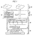
- FIG. 1 of the accompanying drawings is a functional representation of user and service interaction in a typical ATM network environment.
- Layer 100 represents the users and layer 101 represents suppliers who provided value added services to users.
- Layer 102 gives some examples of value added network services such as additional telephoning features, provision of video data, transfer of data files and the like, and layer 103 shows the various functional layers of the actual ATM network.
- the basic unit of an ATM network is the ATM switch. Such a switch will be described in greater detail hereinafter but each switch supports several hundred users and provides the requisite links between the users and other ATM switches in the network.
- VP networks differ in two ways from the traditional telephone network. In a traditional telephone network when a user wishes to access another user a fixed channel is established via the various nodes and switches and this channel either has the ability to carry the data or not.
- a VP network each user is allocated a bandwidth appropriate to his assumed needs in the various connection types and the ATM network management provides bandwidth by selecting a route from all of the available paths in the network.
- a link is an ATM transmission path which provides bandwidth between transmission end points. Normally such a link will be a fibre optic one.
- a number of transmission paths and transmission end points form the transmission capability of the network which is provided to the virtual path (VP) level.
- the transmission end points are ATM switches which route traffic over VP links.
- VP connections A concatenation of VP links is terminated by VP connection end points to form VP connections which are simply called VPs in the remainder of this specification.
- VPs enable the ATM transport network to provide either teleservices to end users via the network service supplier layer 103 or raw bandwidth to value added service suppliers at layer 102.
- a set of VPs are provided to the VC level such that at this level, VPs are interconnected by VC links.
- the resulting concatenation of VC links form a VC connection which are used to transport these teleservices.
- Nodes, links and VP's can all be considered as network resources and in a typical network each is represented by a distributed object. Thus information concerning the network can be obtained by calling function acting on these distributed objects. The importance of this arrangement to the present invention will become apparent hereinafter.
- More than one connection is usually used to provide an end-to-end service association or call to a user/customer of the network.
- Each of the connections in a call have certain characteristics such as bandwidth utilisation profile and performance targets that it shares with other connections of the same type.
- NRM Network Resource Management
- TCM Traffic Control Management
- NRM deals with VP bandwidth management, VP routing, virtual channel (VC) routing strategies, VP and link load balancing, VP Topology Management and quality of service (QoS) verification.
- QoS quality of service
- the performance management in ATM networks is an extremely complex problem due to many factors. Amongst these are the fact that each user has the potential of a plurality of connection types and because of the VP model of the network the combination of the number of different connection types with the number of potential virtual paths between the ATM switches in the network rapidly becomes extremely large. Adding to the problem is the variability of the traffic characteristics and controls at many levels together with the necessity to plan ahead for substantially larger networks.
- VPBM Virtual Path Bandwidth Management
- Telecommunications Management Network Telecommunications Management Network
- virtual path bandwidth management as applied to ATM networks is a network management function which aims to ensure that virtual paths have the right size, allocation and route.
- the difficulties of carrying out this function include:
- TTN telecommunication management network
- the present invention is concerned with providing a solution to the above problems.
- one concern of the present invention is to provide a system for managing bandwidth in an ATM network.
- the present invention is concerned with providing a generic approach to a range of problems in ATM management.
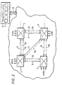
- FIG. 2 of the accompanying drawings shows an ATM network consisting of four ATM switches 1, 2, 3 and 4.
- high bandwidth links are provided between the switches by optical fibres indicated at 5.
- switch 1 is connected directly to switches 2 and 4 and also to switch 3, whilst switches 2 and 4 are respectively connected to 1 and 3.
- each switch will support several hundreds of users and each user in this embodiment has the potentiality of three different connection types with each connection type having a different bandwidth allocated by the VP bandwidth naturally.
- each of the links 5 is capable of carrying the three different connection types which have already been discussed.
- the number and range of connection types can, of course, be varied.
- numerals 50 to 56 represent VPs carried over the links 5.
- VP56 can be considered as providing a direct path between switches 2 and 4. In a physical sense VP56 passes through switch 3 but cannot terminate at switch 3. Thus in effect it does provide a direct path between switch 2 and switch 4.
- the provision of VPCs of this type is a decision of the management function and will depend on, for example, expected traffic volumes.
- a management system is indicated at 6.
- This system comprises a plurality of programmable computers 7 and communicates with the network via an interface indicated at 8.
- This interface can comprise one or more VPs or virtual circuits.
- the function of the programmable computers will be described in greater detail hereinafter. It is conceivable that a single computer can be used in the management system. The number and range of connection types can be varied.
- FIG. 3 shows switch 1 linked to switch 2 of Figure 2.
- a first user is indicated at 10, this user being physically linked to switch 1, and a second user is shown at 11, the second user being physically linked to switch 2.
- the physical links between user 10 and switch 1 are terminated by a port 12, the physical link between switch 1 and switch 2 is terminated by respective ports 13 and 14 and the physical link between user 11 and switch 2 is terminated by a port 15.
- Ports perform the function of line termination so that ATM cells arriving at a port are delivered to the switch and likewise the cells leaving the switch are delivered to the port for transmission.
- the VP/VC switching function is indicated at 20 and the routing tables are indicated at 21.
- the call handling functions of the switch comprise signalling and routing strategies for VC routings and these are shown at 22 and 23.
- the connection acceptance control function (CAC) is shown at 24 and is responsible for accepting or rejecting a new connection onto the network depending on the available capacity left in the network.
- the source policing (SP) function shown at 25 ensures that users do not go above their contracted traffic volumes.
- VPM virtual path management
- the switch is connected via a path indicated at 28 to the management system 6.
- the Synchronous Digital Hierarchy (SDH) will be used as the transport layer of the ATM network being described.
- SDH Synchronous Digital Hierarchy
- the ATM cells generated at the ATM layer will be loaded into appropriate SDH frames before being transmitted over SDH networks to the destination switch.
- SDH termination points upon receiving SDH frames by SDH termination points they are unloaded into ATM cells and delivered to the ATM switching functions.
- the termination points 26 and 27 of the two switches are shown as being divided into ATM termination points and SDH termination points to indicate this shared functionality.
- a user sets up a connection or a call to another user.
- the network switch to which the user is connected in this case switch 1, using the call handling functions, VPM and CAC and by talking to other switches on the path to the destination, allocates a virtual circuit by giving it a VP and VC address and updating the routing tables in the switches.
- the dotted lines VP1 and VP2 show a virtual circuit set up between the two end points as represented by the users. As these are virtual paths it will be appreciated that the actual physical links along which the data will pass from one user to another need not be the direct one between switch 1 and switch 2.
- the present embodiment utilises a distributed set of autonomous objects, which will hereafter be referred to as agents, in the programmable computers 7 located in the management system 6. Additionally in the present embodiment the agents have been kept very simple by having no state and no learning capability.
- agents autonomous objects
- the agents have been kept very simple by having no state and no learning capability.
- One of the benefits of this simplicity is that the quantity and complexity of code required in the running of the system will be small. The complexity of behaviour required to manage a large network emerges from the interaction between the agents.
- a set of agents which dynamically tune the VP network based on network performance measurements fall into three categories or sets. These three categories are diagrammatically represented in Figure 4.
- the first category of agent is shown at 30 and will be referred to as VPC bundle agents which are responsible for a set of VPCs and their supporting VP links.
- the second type of agent is shown at 31 and is referred to as a link agent which is responsible for a physical link and the third type of agent is shown at 32 and is referred to as a coordinator agent which is responsible for coordinating actions taken in response to a network condition to prevent the other agents from performing conflicting actions.
- the first of the agents to be described is the VPC bundle agent 30.
- the behaviour of this agent is described by the two rules shown in Figure 5 of the accompanying drawings.
- the first rule shown in Figure 5 is rule 1 and this rule fires at step 10 when new data arrives from the network. Essentially this rule detects if a problem is present and if this is the case requests the assistance of a coordinator agent 32.
- the rule acts to find the VPC which is the most heavily utilised.
- the rule checks if the utilisation level of the most heavily utilised VPC is over a predetermined threshold or not. If the answer is "Yes" a problem does exist and a request is sent at step 13 to the coordinator agent to find spare bandwidth. If the answer is "No" there is no problem and the rule ends with step 14.
- Rule 2 of Figure 5 fires if the VPC bundle agent 30 receives a request to change the bandwidth of a VPC. Such a request is received at Step 20, carried out at Step 21 and the rule ends with Step 22.
- the behaviour of the coordinator agent 32 is described by the three rules 3, 4 and 5 shown in Figure 6 of the accompanying drawings.
- the first rule in Figure 6 is Rule 3 which fires at step 30 when new data is received from the network via a VPC bundle agent 30 in response to that agent having received a positive answer at step 12 of Rule 1 and having sent a request for spare bandwidth in accordance with step 13 of that rule.
- the coordinator agent determines at Step 31 whether or not it is free to assist. If it is free the coordinator agent obtains at Step 32 the links that the problem VPC traverses. Once the links have been obtained by Step 32 the coordinator agent queries the corresponding link agents to report to it any available bandwidth. This is done in Step 33.
- Rule 3 ends either with the decision at Step 31 that the coordinator is not free or with the request to the link agents in Step 33.
- the termination of the rule is shown at Step 34.
- the second rule associated with each coordinator agent is Rule 4 of Figure 6 and this rule fires when the coordinator agent receives an event stating how much bandwidth is available on a particular link.
- Step 41 of Rule 4 is a decision as to whether or not all of the link agents have reported their available bandwidth. If all the agents do not report then the rule ends at Step 45. However, if all agents have reported the next step, Step 42, involves a decision by the coordinator agent as to whether or not the bandwidth reported by the links is sufficient to solve the problem. If the answer to Step 42 is "Yes" the coordinator agent asks the link agents for instructions as to how the bandwidth can be recovered.
- Step 44 If the answer at Step 42 is "No", Step 43 sends a failure message to the VPC bundle agent of the problem VPC. In either case the rules end at Step 45.
- the third rule associated with the coordinator agent 32 is Rule 5 and this rule fires at Step 50 when the coordinator agent receives an event describing how to cover bandwidth on a link. Such an event is generated by the link agent in response to the message generated at Step 44 of Rule 4.
- Step 51 proceeds with the coordinator agent sending instructions to the links to perform the actions which had been reported at Step 51. This is shown at Steps 53 and 54.
- the last of the three agents is the link agent 31.
- the behaviour of this agent is described by the two rules 6 and 7 shown in Figure 7.
- Rule 6 fires at Step 60 when the link agent receives a request for available bandwidth sent by a coordinator agent in accordance with Step 33 of Rule 3.
- the link agent calculates the available bandwidth at Step 62 it compares the available bandwidth with a preset threshold. If the answer is that more bandwidth is available, the link agent sends at Step 63 a message to this effect to the coordinator. This corresponds to the link agent fulfilling the requirement for Step 51 of Rule 5. If no more bandwidth is available the rule sends that message at Step 64 to the coordinator. The rule ends at Step 65.
- the second rule covering the behaviour of a link agent 31 is Rule 7.
- This rule fires at Step 70 when the link agent receives a request to free up an amount of bandwidth, this request corresponding to Steps 53 and 54 of Rule 5.
- the link agent calculates the bandwidth to be released and at Step 72 sends to the appropriate coordinator agent 32 an instruction concerning the amount of bandwidth to be released.
- Rule 7 ends at Step 73.
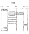
- Figure 8 of the accompanying drawings is a diagram showing the temporal sequence and paths between the agents of messages sent during the tuning of bandwidths for a VPC.
- the VP Topology Problem Management System employs distributed agents. Also the physical connection and switches of the system are similar to those described with reference to Figures 2 and 3 so that the VP Topology Problem Management System resides in the plurality of programmable computers 7 shown in Figure 2.
- the VP Topology Problem Management System utilises a distributed set of autonomous agents in the programmable computers 7. As in the previous embodiment the agents have been kept very simple by having no state and no learning capacity. In the present embodiment it utilises two agent types 200, 201 illustrated in Figure 9 of the accompanying drawings.
- the agent type indicated at 200 will hereinafter be referred to as a monitor agent and the agent type 201 will hereinafter be referred to as a VP agent.
- the number of monitor agents will be in this embodiment the same as the number of links in the network and each monitor agent 200 is responsible for identifying a VP Topology problem and then notifying appropriate VP agents 201 to deal with the identified problem.
- each monitor agent monitors its link and the VPs that use the link for the conditions that indicate a problem.
- the rule governing the behaviour of a monitor agent 200 will be referred to as Rule 8 and fires at Step S100 when new data arrives from the link being monitored by the agent.
- the rule acts to calculate the utilisation levels of the link. This is done by calculating the sum of the bandwidth allocated to the VPs using the link. If this sum is equal to, or exceeds a predetermined threshold, then a VP Topology problem is identified. This is shown at Step S102.
- the actual process carried out by the monitor agent 201 at step S101 is as follows.
- Call Acceptance Control as shown at 24 in Figure 3 is responsible for accepting or rejecting a new connections onto the network depending on the capacity left in the network.
- Each connection type has an associated 'effective bandwidth' which is the amount of bandwidth the CAC allows for an actual connection of that type.
- CAC subtracts the sum of the effective bandwidth's for active calls on the VP from the bandwidth that has been reserved for it on the links it traverses.
- Each VPC has a 'load factor' which says that the CAC should only accept calls up to a certain utilisation. If there is enough spare effective bandwidth, after taking any load factor into account, the connection is accepted.
- each VP may carry a number of different connection types, with different effective bandwidths.
- the monitor agent threshold is set by calculating the effective bandwidth for each VP carried by a link above which the next connection request may be rejected. These bandwidths are summed to find the maximum effective bandwidth that could be allocated. A management policy will then decide a point below this to set as the threshold to trigger a Topology problem.
- each of the VP agents 201 which are associated with a VP which uses the problem link and the other VP agents concerned with the problem.
- each network resource is represented by a distributed object.
- Each object representing a link has a reference to the objects representing the VP's that it carries.
- each of these objects has a reference to the VP agents that have an interest in them.
- Each VP agent 201 represents a VP for a particular Quality of Service (QoS).
- QoS Quality of Service
- each VP agent 201 The behaviour of each VP agent 201 is described by the rules illustrated in Figures 11 and 12.
- Figure 11 illustrates a Rule 9 which is triggered when a VP agent 201 receives a VP Topology problem message in response to a signal from a monitor agent 200 sent in response to a "YES" output at Step 203 in previously described Rule 8.
- Rule 8 is triggered at Step S110 when the VP agent 201 receives a notification that a VP Topology problem is present.
- Rule 8 carries out a series of functions which can be categorised as "preparing a bid". The agent prepares the bid by searching for a new route through the network that avoids the problem link and has appropriate spare capacity in all the links it will traverse.
- the bid is a numerical score based on the bandwidth that will be moved and the amount of spare capacity along the new route. If no route can be found a score guaranteed never to win will be produced.
- the VP agent sends its bid to all the other VP agents which were notified by the monitor agent 200 that a VP Topology problem existed.
- Figure 12 illustrates Rule 10. This rule is triggered at Step S120 when a bid is received from another agent.
- the bid is recorded along with any other bid which has been generated by any other VP agent involved in the problem and which had been notified by the monitor agent 200 of the problem.
- the VP agent can determine if its bid is best. This is illustrated at Step S122. If all the bids have been received the rule proceeds to Step S123 where the agent determines if its bid is the best. If its bid is not the best it again takes no further action. If the VP agents own bid is the best it then implements a set of actions to create a bypass for the link which caused the initial problem.
- Step S124 This is done at Step S124 and comprises the steps of:
- Figures 13A and 13B The results of these operations are illustrated in Figures 13A and 13B in which Figure 13A shows a network configuration when a VP Topology problem has arisen and Figure 13B shows the results of the activity of the already described Monitor and VP agents.
- the network shown in Figures 13A and 13B is similar to that shown in Figure 2. It will be seen that the links which had been generally indicated at 5 in Figure 2 are now individually numbered 5(1), 5(2), 5(3), 5(4) and 5(5).
- link 5(1) consists of 2 VPCs, VPC1 and VPC2.
- the Bandwidth management system tries to increase the bandwidth of VPC2 but fails because there is no spare capacity.
- the Topology management system identifies the problem and replaces VPC1 with VPC1' that uses LINK 3 and LINK 2 as has been already described with regard to Figures 13a, 13b and 14.
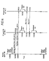
- Figure 14 shows the temporal sequence of messages between the monitor agent (200) which monitors link 5(1) of Figure 13A and the two VP agents (201) responsible for VPC1 and VPC2 respectively.
- the first action in Figure 14 is the monitor agent reading data from the link 5(1) in accordance with Step S100 of Rule 8.
- Step S101 of Rule 8 the existence of a VP Topology problem is notified to the respective VP agents representing VPC1 and VPC2 respectively. In practice these two notifications would be virtually simultaneous.
- the two VP agents carry out the steps of Rule 9 and in particular send out respective bids at S112(9) to each other.
- the bid of the VP agent for VPC1 wins and as a result the winning bid is implemented at S124(10).
- VPC1 has been deleted and replaced by VPC1' the physical path of which passes via ATM switch 3 but as was explained with regard to VPC 56 of Figure 2 cannot terminate at switch 3.
- VPC1' Once the new VPC (VPC1') has been created (as shown in 13B) data about it will start to arrive from the network. Similarly when the old VPC (VPC1) has been deleted data about it will no longer arrive from the network.
- the Topology Management System just described is capable of operating independently of the bandwidth management system described with respect to Figures 1 to 8 and that the converse is also applicable. However it is preferred for the two systems to operate in parallel.
- the agents described will all reside in the general purpose computers 7 of Figure 2. It is thus essential that the agents shown in Figure 4 are capable of taking the changes caused by the Topology Management System into account.
- Topology Management system makes the system more robust since the failure of a VP agent will only means that it is not involved in problem solution.
- VP agent failure is detected by having a time period in which all bids must be received. If VP agent's bid is not received in this time period then it is excluded from the problem but the problem can still be solved by the other VP agents. If there were a controller agents that received these bids to make the decision and this controller agent failed then the problem could not be solved.
- Topology Management system could incorporate central controller but the more distributed control mechanism just described provides greater security in generation for the reasons just given.
- Figure 15 of the accompanying drawings is an illustration of the parallel working of the bandwidth of Topology Management Systems and is effectively a combination of Figure 8 and of Figure 14 with the bandwidth management system slightly simplified in that only a single link agent 31 is shown.
- the bandwidth management system reads the network data at T 0 and the Topology Management System reads the network data at T 1 .
- Bandwidth management fails at T 2 ;
- Topology Management alters the network at T 3 by replacing VPC1 by VPC1';
- Bandwidth management reads the new network data at T 4 with successful tuning indicated at T 5 . Further readings by both management sub-systems at T 6 and T 7 indicate no further problems.
- the two management systems can operate over different timescales and that there is no need for there to be a specific integration of these timescales.
- the two systems can operate entirely independently provided that changes in the network configuration are recognised by the two systems.
Abstract
Description
Carries two VPCs;
| VPC1 | reserved bandwidth | 100Mbs |
| load factor | 0.9 | |
| connection types | conn1 conn2 |
| VPC2 | reserved bandwidth | 55Mbs |
| load factor | 0.8 | |
| connection types | conn3 |
100*0.9 = 90Mbs available for connections
90/7 = 12.9, so 12 connections can be accepted.
12*7 = 84Mbs
42Mbs
Claims (27)
- A management system for an Asynchronous Transfer Mode, ATM, virtual path network in which the physical connections are provided by broadband links (5, Link 1, Link 2, Link 3, Link 4, Link 5) between ATM switches (1, 2, 3, 4), and comprising electronic data processing means (7) connectable to individual ATM switches (1, 2, 3, 4) in an ATM virtual path network, and operable, when in use, to measure current network load in individual links (5) and virtual paths (50-56, VPC1, VPC2) of the network, characterised by the electronic data processing means (7) further including sets of inter-communicating distributed software agents (30, 31, 32, 200, 201) for carrying out management of the network in response to measured load and management requirements, and in that at least some of the agents (30, 201) are each associated with a respective one, or a sub-set, of the virtual paths (50-56, VPC1, VPC2) of the network.
- A system according to claim 1, wherein once the initial parameters have been set the system operates entirely in response to measured load and management requirements.
- A system according to claim 1 or 2, wherein the distributed agents (30, 31, 32, 200, 201) have no state and no learning capability.
- A system according to any preceding claim, wherein the agents (30, 31, 32, 200, 201) include three sets of distributed agents (30, 31, 32) for carrying out bandwidth management of the system, the first set comprising agents (30) each of which is associated with a respective one, or a sub-set, of the virtual paths (50-56) of the network, a second set of agents (31) responsible for physical links (5), and a third set of agents (32) for handling performance events.
- A management system according to claim 4, wherein each agent (30) of said first set is associated with a plurality of virtual paths (50-56) and is adapted to respond to a lack of bandwidth in one of its associated virtual paths (50-56) to generate a request to an agent (32) of said third set to obtain bandwidth.
- A management system according to claim 5, wherein each one of the agents (32) of the third set of agents is adapted, in response to a request from an agent (30) of the first set of agents, to request information regarding the availability of bandwidth on one or more physical links (5) from one or more of the agents (31) of the second set of agents, the or each agent (31) from the second set of agents responding to a request from an agent (32) of the third set of agents by sending to the requesting agent (32) information specifying the available bandwidth on its associated link (5).
- A management system according to claim 6, wherein, in response to bandwidth information received from the or each agent (31) of said second set of agents, the or each agent (32) of the third set of agents is adapted to instruct the or each appropriate agent (31) of the second set of agents as to how bandwidth is to be released.
- A management system according to claim 7, wherein the or each agent (31) of said second set of agents so instructed by one (32) of said third set of agents is adapted to calculate the bandwidth to be released in response to the request and to send to the third set agent (32) an instruction concerning the amount of bandwidth to be released and the identity or identities of the virtual path or paths (50-56) from which the bandwidth should be released.
- A management system according to claim 8, wherein in response to the instructions received from the or each second set agent (31), the third set agent (32) is adapted to instruct the first set agent (30) which made the central request to increase bandwidth to meet its requirements, and to instruct the or each first set agent (30), identified by the or each second set agent (31) which carried out the bandwidth calculations, to reduce its bandwidth to meet the requirements of the centrally requesting first set agent (30).
- A management system according to any one of the preceding claims further comprising monitoring means (200) for determining if a bandwidth problem exists over a link or links (Link 1, Link 2, Link 3, Link 4, Link 5) of the network and for notifying one or more of a plurality of virtual path agents (201) each of which is associated with a respective one, or a sub-set, of the virtual paths (VPC1, VPC2) of the network, wherein the virtual path agents (201) are further adapted to identify a new route (VPC1') through the network that both avoids the problem link (Link 1) and has spare capacity, and wherein the system further comprises means (201) for selecting the route identified (VPC1') and creating a new virtual path connection (VPC1') over a link or a number of links (Link 2, Link 3) of the network.
- A system according to claim 10, wherein said monitoring means (200) is adapted to calculate the sum of the bandwidths allocated to virtual path connections (VPC1, VPC2) which are using the link (Link 1), to compare the sum with a predetermined threshold, and to notify the or each virtual path agent (201) associated with the virtual paths (VPC1, VPC2) of the link (Link 1) that a problem exists.
- A system according to claim 11, wherein said monitoring means (200) comprises a plurality of distributed monitoring agents (200), there being a monitor agent (200) for each link (Link 1, Link 2, Link 3, Link 4, Link 5).
- A system according to any of claims 10 to 12, wherein each virtual path agent (201) is adapted to generate, on receipt of notification of a problem by said monitoring means (200), a bid based on the bandwidths to be moved and the amount of spare capacity along the new route (VPC1') after the virtual path agent (201) has identified a route, whereby one of the virtual path agents (201) may select a new route (VPC1') in response to the best bid generated.
- A system according to claim 13, wherein each virtual path agent (201) is adapted to send a bid to each virtual path agent (201) notified by said monitoring means (200), to determine if its own generated bid is the best bid out of all of those generated by all of the virtual path agents notified by said monitoring means (200) and, if the determination is positive, to implement a set of actions to create a bypass for the link (Link 1) which caused the initial problem.
- A method of managing an Asynchronous Transfer Mode, ATM, virtual path network in which the physical connections are provided by broadband links (5, Link 1, Link 2, Link 3, Link 4, Link 5) between ATM switches (1, 2, 3, 4), and comprising electronic data processing means (7) connectable to individual ATM switches (1, 2, 3, 4) in an ATM virtual path network, the method comprising using the electronic data processing means to measure current network load in individual links (5) and virtual paths (50-56, VPC1, VPC2) of the network, characterised by utilising sets of inter-communicating distributed software agents (30, 31, 32, 200, 201), running on the electronic data processing means (7), to carry out management of the network in response to the measured load and to management requirements, and in that at least some of the agents (30, 201) are each associated with a respective one, or a sub-set, of the virtual paths (50-56, VPC1, VPC2) of the network.
- A method according to claim 15, wherein once the initial parameters have been set the management of the network operates entirely in response to measured load and management requirements.
- A method according to claim 15 or claim 16, wherein the distributed agents have no state and no learning capability.
- A method according to any one of claims 15 to 17, wherein the agents (30, 31, 32, 200, 201) include three sets of distributed agents (30, 31, 32) for carrying out bandwidth management of the system, the first set comprising agents (30) each of which is associated with a respective one, or a sub-set, of the virtual paths (50-56) of the network, a second set of agents (31) responsible for physical links (5), and a third set of agents (32) for handling performance events.
- A method according to claim 18, wherein each agent (30) of said first set is associated with a plurality of virtual paths (50-56) and responds to a lack of bandwidth in one of its associated virtual paths (50-56) by generating a request to an agent (32) of said third set to obtain bandwidth.
- A method according to claim 19, wherein each one of the agents (32) of the third set of agents, in response to a request from an agent (30) of the first set of agents, requests information regarding the availability of bandwidth on one or more physical links (5) from one or more of the agents (31) of the second set of agents, and wherein the or each agent (31) from the second set of agents responds to a request from an agent (32) of the third set of agents by sending to the requesting agent (32) information specifying the available bandwidth on its associated link (5).
- A method according to claim 20, wherein, in response to bandwidth information received from the or each agent (31) of said second set of agents, the or each agent (32) of the third set of agents instructs the or each appropriate agent (31) of the second set of agents as to how bandwidth is to be released.
- A method according to claim 21, wherein the or each agent (31) of said second set of agents so instructed by one (32) of said third set of agents calculates the bandwidth to be released in response to the request and sends to the third set agent (32) an instruction concerning the amount of bandwidth to be released and the identity or identities of the virtual path or paths (50-56) from which the bandwidth should be released.
- A method according to claim 22, wherein in response to the instructions received from the or each second set agent (31), the third set agent (32) instructs the first set agent (30) which made the central request to increase bandwidth to meet its requirements, and instructs the or each first set agent (30), identified by the or each second set agent (31) which carried out the bandwidth calculations, to reduce its bandwidth to meet the requirements of the centrally requesting first set agent (30).
- A method according to any one of claims 15 to 23, further comprising determining if a bandwidth problem exists over a link or links (Link 1, Link 2, Link 3, Link 4, Link 5) of the network and notifying one or more of a plurality of virtual path agents (201) each of which is associated with a respective one, or a sub-set, of the virtual paths (VPC1, VPC2) of the network, and wherein each thus notified virtual path agent (201) attempts to identify a new route (VPC1') through the network that both avoids the problem link (Link 1) and has spare capacity, and wherein the method further comprises selecting the route identified (VPC1') and creating a new virtual path connection (VPC1') over a link or a number of links (Link 2, Link 3) of the network.
- A method according to claim 24, wherein said monitoring is carried out by a plurality of distributed monitor agents (200), each of which is associated with a respective one or a subset of the links (Link 1, Link 2, Link 3, Link 4, Link 5), which monitor agents (201) calculate the sum of the bandwidth allocated to the actual virtual paths (VPC1, VPC2) which constitute the or each link (Link 1), compare the sum with a predetermined threshold, and, if the comparison indicates there is a problem, notify the respective virtual path agents (201) that a problem exists.
- A method according to claim 24 or claim 25, wherein each virtual path agent (201), on receipt of a notification of a problem by a monitor agent (200), generates a bid based on the bandwidth to be moved and the amount of spare capacity along the new route (VPC1'), after the virtual path agent has identified a route, whereby one of the virtual path agents (201) may select a new route (VPC1') in response to the best bid generated.
- A method according to claim 26 wherein each virtual path agent (201) sends a bid to each virtual path agent (201) notified by said monitoring means (200), determines if its own generated bid is the best bid out of all of those generated by all of the virtual path agents (201) notified by said monitoring means (200) and, if the determination is positive, implements a set of actions to create a bypass for the link (Link 1) which caused the initial problem.
Applications Claiming Priority (3)
| Application Number | Priority Date | Filing Date | Title |
|---|---|---|---|
| GB9612363 | 1996-06-13 | ||
| GB9612363A GB9612363D0 (en) | 1996-06-13 | 1996-06-13 | ATM network management |
| PCT/GB1997/001591 WO1997048214A2 (en) | 1996-06-13 | 1997-06-12 | Atm network management |
Publications (2)
| Publication Number | Publication Date |
|---|---|
| EP0904647A2 EP0904647A2 (en) | 1999-03-31 |
| EP0904647B1 true EP0904647B1 (en) | 2005-12-14 |
Family
ID=10795231
Family Applications (1)
| Application Number | Title | Priority Date | Filing Date |
|---|---|---|---|
| EP97926107A Expired - Lifetime EP0904647B1 (en) | 1996-06-13 | 1997-06-12 | Atm network management |
Country Status (6)
| Country | Link |
|---|---|
| EP (1) | EP0904647B1 (en) |
| JP (1) | JP2000512453A (en) |
| AU (1) | AU3099497A (en) |
| DE (1) | DE69734878T2 (en) |
| GB (1) | GB9612363D0 (en) |
| WO (1) | WO1997048214A2 (en) |
Families Citing this family (11)
| Publication number | Priority date | Publication date | Assignee | Title |
|---|---|---|---|---|
| JP3634942B2 (en) * | 1997-06-10 | 2005-03-30 | 株式会社日立コミュニケーションテクノロジー | Packet switching network and packet switching device |
| US6108304A (en) | 1996-03-08 | 2000-08-22 | Abe; Hajime | Packet switching network, packet switching equipment, and network management equipment |
| JPH10190733A (en) | 1996-12-25 | 1998-07-21 | Hitachi Ltd | Ip switch, interface circuit and atm switch used for the ip switch and ip switch network system |
| US6046999A (en) | 1996-09-03 | 2000-04-04 | Hitachi, Ltd. | Router apparatus using ATM switch |
| IL125310A (en) | 1998-07-12 | 2002-02-10 | Eci Telecom Ltd | Method and system for managing varying traffic load in telecommunication network |
| FI107098B (en) * | 1999-06-08 | 2001-05-31 | Nokia Networks Oy | Choosing a virtual bus or channel in a telecommunications network |
| US6671724B1 (en) * | 2000-03-21 | 2003-12-30 | Centrisoft Corporation | Software, systems and methods for managing a distributed network |
| US7260635B2 (en) | 2000-03-21 | 2007-08-21 | Centrisoft Corporation | Software, systems and methods for managing a distributed network |
| WO2002037724A1 (en) * | 2000-10-31 | 2002-05-10 | Dynarc Ab | Method of adjusting a bandwidth capacity of a dynamic channel |
| JP4711794B2 (en) * | 2005-09-28 | 2011-06-29 | 富士通株式会社 | Ring network bandwidth changing method and node device |
| JP4711795B2 (en) * | 2005-09-28 | 2011-06-29 | 富士通株式会社 | Ring network bandwidth increasing / decreasing method and node device |
Family Cites Families (1)
| Publication number | Priority date | Publication date | Assignee | Title |
|---|---|---|---|---|
| US5347511A (en) * | 1993-06-07 | 1994-09-13 | International Business Machines Corp. | Traffic management in packet communications networks |
-
1996
- 1996-06-13 GB GB9612363A patent/GB9612363D0/en active Pending
-
1997
- 1997-06-12 AU AU30994/97A patent/AU3099497A/en not_active Abandoned
- 1997-06-12 EP EP97926107A patent/EP0904647B1/en not_active Expired - Lifetime
- 1997-06-12 DE DE69734878T patent/DE69734878T2/en not_active Expired - Lifetime
- 1997-06-12 WO PCT/GB1997/001591 patent/WO1997048214A2/en active IP Right Grant
- 1997-06-12 JP JP10501366A patent/JP2000512453A/en active Pending
Also Published As
| Publication number | Publication date |
|---|---|
| GB9612363D0 (en) | 1996-08-14 |
| WO1997048214A2 (en) | 1997-12-18 |
| EP0904647A2 (en) | 1999-03-31 |
| DE69734878D1 (en) | 2006-01-19 |
| JP2000512453A (en) | 2000-09-19 |
| DE69734878T2 (en) | 2006-08-10 |
| AU3099497A (en) | 1998-01-07 |
| WO1997048214A3 (en) | 1998-02-19 |
Similar Documents
| Publication | Publication Date | Title |
|---|---|---|
| US6400687B1 (en) | ATM network management | |
| US6400681B1 (en) | Method and system for minimizing the connection set up time in high speed packet switching networks | |
| US6934249B1 (en) | Method and system for minimizing the connection set up time in high speed packet switching networks | |
| US6842463B1 (en) | Automated and adaptive management of bandwidth capacity in telecommunications networks | |
| US6400685B1 (en) | Heterogenous traffic connection admission control system for ATM networks and a method thereof | |
| CA2069195C (en) | Communication switching system | |
| US6665264B1 (en) | Connection admission control for connection orientated networks | |
| US5467348A (en) | Bandwidth allocation system of virtual path in asynchronous transfer mode | |
| US6104699A (en) | Method and device for partitioning physical network resources | |
| JP4368981B2 (en) | Load-balanced UBR routing in ATM networks | |
| US20040042402A1 (en) | Method and system for a local and fast non-disruptive path switching in high speed packet switching networks | |
| JPH09186701A (en) | Optimum band width assignment method and its device | |
| JP2000151652A (en) | Method, system and network for dynamically adjusting bandwidth for consecutive bit rate virtual path connection | |
| EP0904647B1 (en) | Atm network management | |
| EP0814583A2 (en) | Method and system for minimizing the connection set up time in high speed packet switching networks | |
| JPH09506749A (en) | Method and apparatus for controlling a communication network | |
| US6842780B1 (en) | Method of management in a circuit-switched communication network and device which can be used as a node in a circuit-switched communication network | |
| EP0838970B1 (en) | Method for shared memory management in network nodes | |
| Bartal et al. | Fast, fair and frugal bandwidth allocation in atm networks | |
| US6542509B1 (en) | Virtual path level fairness | |
| EP1008274B1 (en) | Method of management in a circuit-switched communication network and device which can be used as a node in a circuit-switched communication network | |
| JP3053356B2 (en) | Bandwidth variable communication device | |
| Bahk et al. | Preventive congestion control based routing in ATM networks | |
| Wong et al. | Bandwidth allocation for virtual paths in ATM networks with dynamic routing | |
| JP2794740B2 (en) | Network resource management method |
Legal Events
| Date | Code | Title | Description |
|---|---|---|---|
| PUAI | Public reference made under article 153(3) epc to a published international application that has entered the european phase |
Free format text: ORIGINAL CODE: 0009012 |
|
| 17P | Request for examination filed |
Effective date: 19981201 |
|
| AK | Designated contracting states |
Kind code of ref document: A2 Designated state(s): DE FR GB IT |
|
| 17Q | First examination report despatched |
Effective date: 20031009 |
|
| GRAP | Despatch of communication of intention to grant a patent |
Free format text: ORIGINAL CODE: EPIDOSNIGR1 |
|
| GRAS | Grant fee paid |
Free format text: ORIGINAL CODE: EPIDOSNIGR3 |
|
| GRAA | (expected) grant |
Free format text: ORIGINAL CODE: 0009210 |
|
| AK | Designated contracting states |
Kind code of ref document: B1 Designated state(s): DE FR GB IT |
|
| PG25 | Lapsed in a contracting state [announced via postgrant information from national office to epo] |
Ref country code: IT Free format text: LAPSE BECAUSE OF FAILURE TO SUBMIT A TRANSLATION OF THE DESCRIPTION OR TO PAY THE FEE WITHIN THE PRESCRIBED TIME-LIMIT;WARNING: LAPSES OF ITALIAN PATENTS WITH EFFECTIVE DATE BEFORE 2007 MAY HAVE OCCURRED AT ANY TIME BEFORE 2007. THE CORRECT EFFECTIVE DATE MAY BE DIFFERENT FROM THE ONE RECORDED. Effective date: 20051214 |
|
| REG | Reference to a national code |
Ref country code: GB Ref legal event code: FG4D |
|
| REF | Corresponds to: |
Ref document number: 69734878 Country of ref document: DE Date of ref document: 20060119 Kind code of ref document: P |
|
| ET | Fr: translation filed | ||
| PLBE | No opposition filed within time limit |
Free format text: ORIGINAL CODE: 0009261 |
|
| STAA | Information on the status of an ep patent application or granted ep patent |
Free format text: STATUS: NO OPPOSITION FILED WITHIN TIME LIMIT |
|
| 26N | No opposition filed |
Effective date: 20060915 |
|
| PGFP | Annual fee paid to national office [announced via postgrant information from national office to epo] |
Ref country code: FR Payment date: 20110630 Year of fee payment: 15 |
|
| PGFP | Annual fee paid to national office [announced via postgrant information from national office to epo] |
Ref country code: GB Payment date: 20110620 Year of fee payment: 15 |
|
| PGFP | Annual fee paid to national office [announced via postgrant information from national office to epo] |
Ref country code: DE Payment date: 20110622 Year of fee payment: 15 |
|
| GBPC | Gb: european patent ceased through non-payment of renewal fee |
Effective date: 20120612 |
|
| REG | Reference to a national code |
Ref country code: FR Ref legal event code: ST Effective date: 20130228 |
|
| REG | Reference to a national code |
Ref country code: DE Ref legal event code: R119 Ref document number: 69734878 Country of ref document: DE Effective date: 20130101 |
|
| PG25 | Lapsed in a contracting state [announced via postgrant information from national office to epo] |
Ref country code: DE Free format text: LAPSE BECAUSE OF NON-PAYMENT OF DUE FEES Effective date: 20130101 Ref country code: FR Free format text: LAPSE BECAUSE OF NON-PAYMENT OF DUE FEES Effective date: 20120702 Ref country code: GB Free format text: LAPSE BECAUSE OF NON-PAYMENT OF DUE FEES Effective date: 20120612 |