EP0904520B1 - Rotorlagerung mit schwimmendem zugring - Google Patents
Rotorlagerung mit schwimmendem zugring Download PDFInfo
- Publication number
- EP0904520B1 EP0904520B1 EP97925522A EP97925522A EP0904520B1 EP 0904520 B1 EP0904520 B1 EP 0904520B1 EP 97925522 A EP97925522 A EP 97925522A EP 97925522 A EP97925522 A EP 97925522A EP 0904520 B1 EP0904520 B1 EP 0904520B1
- Authority
- EP
- European Patent Office
- Prior art keywords
- rotor
- header
- shoulders
- lug
- slots
- Prior art date
- Legal status (The legal status is an assumption and is not a legal conclusion. Google has not performed a legal analysis and makes no representation as to the accuracy of the status listed.)
- Expired - Lifetime
Links
- 230000002093 peripheral effect Effects 0.000 claims description 9
- 230000001172 regenerating effect Effects 0.000 claims description 7
- 210000002105 tongue Anatomy 0.000 description 10
- 239000007789 gas Substances 0.000 description 9
- 239000003546 flue gas Substances 0.000 description 5
- UGFAIRIUMAVXCW-UHFFFAOYSA-N Carbon monoxide Chemical compound [O+]#[C-] UGFAIRIUMAVXCW-UHFFFAOYSA-N 0.000 description 4
- 238000002485 combustion reaction Methods 0.000 description 2
- 238000006243 chemical reaction Methods 0.000 description 1
- 238000004519 manufacturing process Methods 0.000 description 1
- 239000000463 material Substances 0.000 description 1
Images


Classifications
-
- F—MECHANICAL ENGINEERING; LIGHTING; HEATING; WEAPONS; BLASTING
- F28—HEAT EXCHANGE IN GENERAL
- F28D—HEAT-EXCHANGE APPARATUS, NOT PROVIDED FOR IN ANOTHER SUBCLASS, IN WHICH THE HEAT-EXCHANGE MEDIA DO NOT COME INTO DIRECT CONTACT
- F28D19/00—Regenerative heat-exchange apparatus in which the intermediate heat-transfer medium or body is moved successively into contact with each heat-exchange medium
- F28D19/04—Regenerative heat-exchange apparatus in which the intermediate heat-transfer medium or body is moved successively into contact with each heat-exchange medium using rigid bodies, e.g. mounted on a movable carrier
- F28D19/041—Regenerative heat-exchange apparatus in which the intermediate heat-transfer medium or body is moved successively into contact with each heat-exchange medium using rigid bodies, e.g. mounted on a movable carrier with axial flow through the intermediate heat-transfer medium
- F28D19/042—Rotors; Assemblies of heat absorbing masses
- F28D19/044—Rotors; Assemblies of heat absorbing masses shaped in sector form, e.g. with baskets
-
- F—MECHANICAL ENGINEERING; LIGHTING; HEATING; WEAPONS; BLASTING
- F28—HEAT EXCHANGE IN GENERAL
- F28D—HEAT-EXCHANGE APPARATUS, NOT PROVIDED FOR IN ANOTHER SUBCLASS, IN WHICH THE HEAT-EXCHANGE MEDIA DO NOT COME INTO DIRECT CONTACT
- F28D11/00—Heat-exchange apparatus employing moving conduits
- F28D11/02—Heat-exchange apparatus employing moving conduits the movement being rotary, e.g. performed by a drum or roller
-
- F—MECHANICAL ENGINEERING; LIGHTING; HEATING; WEAPONS; BLASTING
- F28—HEAT EXCHANGE IN GENERAL
- F28F—DETAILS OF HEAT-EXCHANGE AND HEAT-TRANSFER APPARATUS, OF GENERAL APPLICATION
- F28F2275/00—Fastening; Joining
- F28F2275/14—Fastening; Joining by using form fitting connection, e.g. with tongue and groove
-
- Y—GENERAL TAGGING OF NEW TECHNOLOGICAL DEVELOPMENTS; GENERAL TAGGING OF CROSS-SECTIONAL TECHNOLOGIES SPANNING OVER SEVERAL SECTIONS OF THE IPC; TECHNICAL SUBJECTS COVERED BY FORMER USPC CROSS-REFERENCE ART COLLECTIONS [XRACs] AND DIGESTS
- Y10—TECHNICAL SUBJECTS COVERED BY FORMER USPC
- Y10S—TECHNICAL SUBJECTS COVERED BY FORMER USPC CROSS-REFERENCE ART COLLECTIONS [XRACs] AND DIGESTS
- Y10S165/00—Heat exchange
- Y10S165/009—Heat exchange having a solid heat storage mass for absorbing heat from one fluid and releasing it to another, i.e. regenerator
- Y10S165/013—Movable heat storage mass with enclosure
- Y10S165/016—Rotary storage mass
- Y10S165/017—Rotary storage mass with thermal expansion compensating means
Definitions
- the present invention relates to rotary regenerative air preheaters which employ a rotor post for rotation of the rotor and more particularly to novel rotor post headers for mounting the rotor diaphragms.
- a rotary regenerative air preheater transfers sensible heat from the flue gas leaving a boiler to the entering combustion air through regenerative heat transfer surface in a rotor which turns continuously through the gas and air streams.
- the rotor which is packed with the heat transfer surface, has a rotor post which is supported through a lower bearing at the lower end of the air preheater and guided through a bearing assembly located at the top end for most vertical flow air preheaters.
- Some vertical flow air preheaters use a top support bearing and a lower guide bearing.
- the rotor is divided into compartments by a number of radially extending plates referred to as diaphragms. Generally, the bottom inboard edge of the diaphragms are set on a ledge on the lower rotor post header and an upper diaphragm tongue is pinned within an annulus in the upper rotor post header.
- the hot flue gas and the combustion air enter the rotor shell from opposite ends and pass in opposite directions over the heat exchange material housed within the rotor. Consequently, the cold air inlet and the cooled gas outlet are at one end of the heat exchanger, referred to as the cold end, and the hot gas inlet and the heated air outlet are at the opposite end of the heat exchanger, referred to as the hot end.
- an axial temperature gradient exists from the hot end of the rotor to the cold end of the rotor. In response to this temperature gradient, the rotor tends to distort and to assume a shape similar to that of an inverted dish (commonly referred to as rotor turndown).
- the upper rotor post header comprises a massive structure to provide an annulus having a sufficient height to allow movement of the diaphragm tongue and flanges having sufficient thickness to withstand the tensile stress imposed by the rotor distortion.
- Such a structure is expensive to manufacture and imposes a large weight burden on the rotor bearing.
- the present invention provides an arrangement of means in an air preheater for mounting rotor diaphragms on the rotor post wherein the mounting means is free to move axially on the rotor post. This reduces the tensile stress on the mounting means, allowing the mass of the mounting means to be reduced.
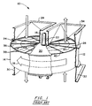
- Figure 1 is a general perspective view of a conventional rotary regenerative air preheater.
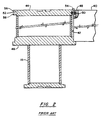
- Figure 2 is a cross-section view, partly broken away, a prior art rotor post and rotor diaphragm of the air preheater of Figure 1.
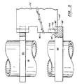
- Figure 3 is an enlarged cross-section view, partly broken away, of the rotor post, the upper and lower rotor post headers and a rotor diaphragm in accordance with the present invention.
- Figure 4 is an enlarged top plan view of a portion of the upper rotor post header of Figure 3 and portions of a plurality of rotor diaphragms.
- Figure 5 is a cross-section view, partly broken away, of an alternate embodiment of the diaphragm and lower rotor postheader of Figure 3.
- Figure 1 of the drawings is a partially cut-away perspective view of a typical bi-sector air preheater 10 showing a housing 12 in which the rotor 14 is mounted on a drive shaft or post 16 for rotation as indicated by the arrow 18.
- the housing is divided by means of the flow impervious sector plates 20, 22 into a flue gas side 24 and an air side 26. Corresponding sector plates are also located on the bottom of the unit.
- the rotor housing is divided into three sectors by the sector plates and include the flue gas sector, the primary air sector, and the secondary air sector.
- the heated air stream forms a hot air stream and leaves the air preheater 10 through the duct connector section 34. Consequently, the cold air inlet and the cooled gas outlet 30 define a cold end of the heat exchanger and the hot gas inlet 28 and the heated air outlet define a hot end of the heat exchanger.
- the rotor 14 is composed of a plurality of sectors 36 with each sector containing a number of basket modules 38 and with each sector being defined by the diaphragms 40.
- the basket modules 38 contain the heat exchange surface.
- the inboard end 42 of the diaphragms 40 are supported on upper and lower rotor post headers 44, 46.
- a tongue 50 radially extends from the upper portion 48 of the inboard end 42 of the diaphragm 40 in conventional air preheaters.
- the tongue 50 is received in an annulus 52 in the upper rotor post header 44 and is pinned in place.
- the air preheater 10 progresses from a cold condition to a hot condition on startup, the resulting deformation causes the tongue 50 to move axially upward on the pin 54.
- Such movement is opposed by friction between the tongue 50 and the pin 54, imposing a tensile stress on the diaphragm tongue 50, the pin 54 and the flanges 56, 58 on the upper rotor post header 44 that define the annulus 52.
- the upper rotor post header 44 must include sufficient structure to provide an annulus 52 having a height that will allow movement of the diaphragm tongue 50 and flanges 56, 58 having a thickness sufficient to withstand the tensile stress imposed by the rotor distortion.
- the upper rotor post header 60 comprises a floating tensile ring having an interior opening 62 for receiving the rotor post 16.
- a plurality of circumferentially spaced radially extending slots 64 are disposed in the outer peripheral portion 66 of the upper rotor post header 60.
- the outboard portion 68 of each slot 64 defines a gap 72 in the peripheral surface 73 of the header 60.
- the inboard portion 70 of each slot 64 defines a pair of shoulders 74, wherein the slot has a T-shape.
- the upper portion 78 of the inboard end 80 of each diaphragm 76 comprises a box-shaped lug 82 which is received in the inboard portion of one of the T-shaped slots 64.
- Each diaphragm 76 has a notch 86 disposed below the lug 82.
- the height H of the notch 86 is at least as great as the thickness T of the upper rotor post header 60.
- the diaphragm 76 is mounted to the upper rotor post header 60 by inserting the outer peripheral portion 66 of the upper rotor post header 60 into the notch 86, positioning the lug 82 of the diaphragm 76 over the inboard portion 70 of the slot 64, and lowering the diaphragm 76 such that the lug 82 is disposed in the inboard portion 70 of the slot 64.
- the rotor deformation causes the upper rotor post header 60 to move axially upward on the rotor post 16.
- the radial force imposed on the upper rotor post header 60 by each diaphragm 76 is offset by the radial force imposed by one or more diaphragms 76 mounted on the opposite side of the upper rotor post header 60. Therefore, the rotor post 16 remains substantially centered within the interior opening 62.
- the thickness T of the upper rotor post header is six (6) inches for a given size and weight rotor.
- Such a header has a mass that is approximately fifty to sixty percent (50-60%) less than the mass of a comparable traditional upper header 44 for the same size and weight rotor, has sufficient mechanical strength to withstand the tensile stress imposed by the diaphragms 76, and may be smaller in diameter than the traditional upper header 44.
- the lower rotor post header 88 is mounted to the rotor by a weld 90.
- the lower segment 92 of the outer peripheral portion 98 of the lower post header 88 radially extends beyond the upper segment 94 of the outer peripheral portion 90 to define a shelf 96.
- the lower portion 100 of the inboard end 80 of each diaphragm 76 rests on the shelf 96, whereby the diaphragms 76 are supported by the lower rotor post header 88.
- the upper segment 94' of the outer peripheral portion 98' of the lower post header 88' comprises a plurality of T-shaped slots 102 and the lower portion 100' of the inboard end 80' of each diaphragm 76' defines a box-shaped lug 104' which is received in a slot 102 to lock the diaphragm 76' to the rotor post 16.
- the bottom surface of each lug 104 rests on the shelf 96' of the lower post header 88'.
- the relative thermal growth that occurred in the mounting connection of the traditional design between the diaphragms 40 and the upper post header 44 is eliminated by accommodating such growth between the bore of the floating tensile ring 60 and the post 16.
- the floating tensile ring 60 is centered on the post 16 by controlling the diameter of the post 16 and the opening or bore 62 of the ring 60 while allowing for thermal growth therebetween with no need for consideration of the actual total weight of the rotor 14 or the individual sectors 36.
- the lower support header 88 of the present invention may be designed almost entirely based upon the dead weight of the rotor 14 since the excess axial load over and above the dead weight due to the relative thermal growth in the upper mounting connection has been reduced or eliminated. As a result, this excess axial loading on the lower header 88 is reduced by approximately eighty to ninety percent (80-90%). Consequently, for a given size and weight rotor 14, the required mass of the lower post header 88 of the present invention is reduced in excess of fifty percent (50%).
- the rotor post shell and connecting welds may be designed based on overturning moment reactions due to air and gas pressure drop through the heat transfer surfaces and radial pressure due to air to gas pressure differentials.
Landscapes
- Engineering & Computer Science (AREA)
- Physics & Mathematics (AREA)
- Thermal Sciences (AREA)
- Mechanical Engineering (AREA)
- General Engineering & Computer Science (AREA)
- Air Supply (AREA)
Claims (15)
- Rotorvorrichtung für einen rotierenden rückgewinnenden Luftvorwärmer, die aus folgendem besteht:einem Rotorständer, der eine im wesentlichen vertikale Rotationsachse definiert, wobei der Rotorständer einen unteren Teil und einen oberen Teil aufweist;einem ersten Rotorkopfstück, das an dem unteren Teil des Rotorständers befestigt ist und von diesem aus radial verläuft;einem zweiten Rotorkopfstück, das eine axiale Öffnung zur gleitenden Aufnahme des oberen Teils des Rotorständers definiert und einen nach außen gerichteten Umfangsteil enthält, der mehrere über den Umfang beabstandete radial verlaufende Schlitze definiert; undmehreren radial verlaufenden Zwischenwänden zum Definieren von Sektoren des Rotors, wobei jede der Zwischenwände aus einem oberen nach innen gerichteten Teil und einem unteren nach innen gerichteten Teil besteht, wobei der untere nach innen gerichtete Teil jeder Zwischenwand das erste Rotorkopfstück in Eingriff nimmt, wodurch das erste Rotorkopfstück die Zwischenwände stützt, wobei der obere nach innen gerichtete Teil jeder Zwischenwand aus einer Fahne besteht, wobei jede der Fahnen in einem der Schlitze aufgenommen wird und Mittel enthält, um die Schlitze in Eingriff zu nehmen, wodurch die radiale Bewegung der Zwischenwände begrenzt wird.
- Rotorvorrichtung nach Anspruch 1, bei der jeder der Schlitze aus einem nach innen gerichteten Teil und einem nach außen gerichteten Teil besteht, wobei der nach innen gerichtete Teil jedes Schlitzes ein Paar Schultern zur Ineingriffnahme mit den Fahnen definiert.
- Rotorvorrichtung nach Anspruch 2, bei der jede der Fahnen ein Paar Schultern definiert, wobei die Schultern der Fahne die Schultern des Schlitzes in Eingriff nehmen.
- Rotorvorrichtung nach Anspruch 1, bei der jede der Zwischenwände weiterhin aus einem unter der Fahne angeordneten Kerbenmittel besteht, wobei das Kerbenmittel zur Aufnahme des nach außen gerichteten Umfangsteils des zweiten Rotorkopfstücks ausgelegt ist.
- Rotorvorrichtung nach Anspruch 4, bei der das zweite Rotorkopfstück eine Dicke T und das Kerbenmittel eine Höhe H aufweist, wobei H ≥ T.
- Rotorvorrichtung nach Anspruch 1, bei der das erste Rotorkopfstück über eine Schweißstelle an dem Rotor befestigt ist.
- Rotorvorrichtung nach Anspruch 1, bei der das erste Rotorkopfstück aus einem oberen nach außen gerichteten Segment und einem unteren nach außen gerichteten Segment besteht, und wobei das untere nach außen gerichtete Segment sich radial über das obere nach außen gerichtete Segment hinaus erstreckt, um ein Fach zu definieren, auf dem die Zwischenwände gestützt werden.
- Rotorvorrichtung nach Anspruch 7, bei der das obere nach außen gerichtete Segment des ersten Rotorkopfstücks mehrere über den Umfang beabstandete radial verlaufende Schlitze definiert und der untere nach innen gerichtete Teil jeder Zwischenwand aus Fahnenmitteln besteht, wobei jedes der Fahnenmittel eingreifbar in einem der Schlitze aufgenommen wird.
- Rotorvorrichtung nach Anspruch 8, bei der jeder der Schlitze aus einem nach innen gerichteten Teil und einem nach außen gerichteten Teil besteht, wobei der nach innen gerichtete Teil jedes Schlitzes ein Paar Schultern definiert.
- Rotorvorrichtung nach Anspruch 9, bei der jedes der Fahnenmittel ein Paar Schultern definiert, wobei die Schultern der Fahnenmittel die Schultern des Schlitzes in Eingriff nehmen.
- Rotorvorrichtung für einen rotierenden rückgewinnenden Luftvorwärmer mit einem vertikalen Rotorständer, wobei der Rotorständer einen unteren und einen oberen Teil aufweist, wobei die Rotorvorrichtung aus folgendem besteht:einem ersten Rotorkopfstück, das an dem unteren Teil des Rotorständers befestigt ist und aus einem oberen nach außen gerichteten Segment und einem unteren nach außen gerichteten Segment besteht, wobei das untere nach außen gerichtete Segment sich über das obere nach außen gerichtete Segment hinaus erstreckt, um ein Fach zu definieren;einem zweiten Rotorkopfstück, das eine axiale Öffnung zur gleitenden Aufnahme des oberen Teils des Rotorständers definiert und einen nach außen gerichteten Umfangsteil enthält, der mehrere über den Umfang beabstandete radial verlaufende T-förmige Schlitze definiert; undmehreren radial verlaufenden Zwischenwänden zum Definieren von Sektoren des Rotors, wobei jede der Zwischenwände aus einem oberen nach innen gerichteten Teil und einem unteren nach innen gerichteten Teil besteht, wobei der untere nach innen gerichtete Teil jeder Zwischenwand das Fach des ersten Rotorkopfstücks in Eingriff nimmt, wobei der obere nach innen gerichtete Teil jeder Zwischenwand aus einer Fahne besteht, wobei jede der Fahnen eingreifbar in einem der Schlitze aufgenommen wird.
- Rotorvorrichtung nach Anspruch 11, bei der jede der Fahnen ein Paar Schultern definiert und jeder der Schlitze ein Paar Schultern definiert, wobei die Schultern der Fahne die Schultern des Schlitzes in Eingriff nehmen, um eine nach außen gerichtete radiale Bewegung der Zwischenwand zu verhindern.
- Rotorvorrichtung nach Anspruch 11, bei der das zweite Rotorkopfstück eine Dicke T aufweist und jede der Zwischenwände weiterhin ein unter der Fahne angeordnetes Kerbenmittel mit einer Höhe H aufweist, wobei H ≥ T.
- Rotorvorrichtung nach Anspruch 11, bei der das obere nach außen gerichtete Segment des ersten Rotorkopfstücks mehrere über den Umfang beabstandete radial verlaufende Schlitze definiert und der untere nach innen gerichtete Teil jeder Zwischenwand aus Fahnenmitteln besteht, wobei jedes der Fahnenmittel eingreifbar in einem der Schlitze aufgenommen wird.
- Rotorvorrichtung nach Anspruch 14, bei dem jedes der Fahnenmittel ein Paar Schultern definiert, wobei die Schultern des Fahnenmittel die Schultern des Schlitzes in Eingriff nehmen.
Applications Claiming Priority (3)
| Application Number | Priority Date | Filing Date | Title |
|---|---|---|---|
| US664145 | 1991-03-04 | ||
| US08/664,145 US5660226A (en) | 1996-06-14 | 1996-06-14 | Rotor post with floating tensile header |
| PCT/US1997/007995 WO1997047938A1 (en) | 1996-06-14 | 1997-05-09 | Rotor post with floating tensile header |
Publications (2)
| Publication Number | Publication Date |
|---|---|
| EP0904520A1 EP0904520A1 (de) | 1999-03-31 |
| EP0904520B1 true EP0904520B1 (de) | 2000-01-12 |
Family
ID=24664740
Family Applications (1)
| Application Number | Title | Priority Date | Filing Date |
|---|---|---|---|
| EP97925522A Expired - Lifetime EP0904520B1 (de) | 1996-06-14 | 1997-05-09 | Rotorlagerung mit schwimmendem zugring |
Country Status (10)
| Country | Link |
|---|---|
| US (1) | US5660226A (de) |
| EP (1) | EP0904520B1 (de) |
| JP (1) | JP3103940B2 (de) |
| KR (1) | KR100284865B1 (de) |
| BR (1) | BR9709730A (de) |
| CA (1) | CA2257718A1 (de) |
| DE (1) | DE69701144T2 (de) |
| ID (1) | ID17284A (de) |
| TW (1) | TW332246B (de) |
| WO (1) | WO1997047938A1 (de) |
Families Citing this family (2)
| Publication number | Priority date | Publication date | Assignee | Title |
|---|---|---|---|---|
| US9810467B2 (en) | 2012-12-13 | 2017-11-07 | Lennox Industries Inc. | Controlling air conditioner modes |
| ES2724481T3 (es) * | 2014-06-13 | 2019-09-11 | Amarant Ind Ab | Rueda térmica |
Family Cites Families (7)
| Publication number | Priority date | Publication date | Assignee | Title |
|---|---|---|---|---|
| US3216488A (en) * | 1962-11-23 | 1965-11-09 | Air Preheater | Rotary regenerative heat exchange apparatus |
| FR2131878B1 (de) * | 1971-03-31 | 1975-07-04 | Wehr Corp | |
| US3891029A (en) * | 1974-02-04 | 1975-06-24 | Air Preheater | Rotor assembly for vertical shaft air preheater |
| US4234038A (en) * | 1978-08-17 | 1980-11-18 | Wehr Corporation | Transfer wheel assembly for an air conditioner and method of making the wheel assembly |
| GB2074301B (en) * | 1980-04-17 | 1983-12-07 | Svenska Rotor Maskiner Ab | Regenerative heat exchangers |
| US4418742A (en) * | 1982-06-07 | 1983-12-06 | The Babcock & Wilcox Company | Rotor construction for rotary regenerative air heater |
| US4773145A (en) * | 1983-09-09 | 1988-09-27 | The Air Preheater Company, Inc. | Method of constructing a cylindrical rotor assembly for a rotary regenerative heat exchanger |
-
1996
- 1996-06-14 US US08/664,145 patent/US5660226A/en not_active Expired - Fee Related
-
1997
- 1997-05-02 TW TW086105840A patent/TW332246B/zh active
- 1997-05-09 JP JP10501591A patent/JP3103940B2/ja not_active Expired - Fee Related
- 1997-05-09 BR BR9709730A patent/BR9709730A/pt not_active Application Discontinuation
- 1997-05-09 KR KR1019980710156A patent/KR100284865B1/ko not_active Expired - Fee Related
- 1997-05-09 EP EP97925522A patent/EP0904520B1/de not_active Expired - Lifetime
- 1997-05-09 WO PCT/US1997/007995 patent/WO1997047938A1/en not_active Ceased
- 1997-05-09 CA CA002257718A patent/CA2257718A1/en not_active Abandoned
- 1997-05-09 DE DE69701144T patent/DE69701144T2/de not_active Expired - Fee Related
- 1997-06-12 ID IDP972008A patent/ID17284A/id unknown
Also Published As
| Publication number | Publication date |
|---|---|
| DE69701144D1 (de) | 2000-02-17 |
| CA2257718A1 (en) | 1997-12-18 |
| KR100284865B1 (ko) | 2001-03-15 |
| EP0904520A1 (de) | 1999-03-31 |
| TW332246B (en) | 1998-05-21 |
| US5660226A (en) | 1997-08-26 |
| JPH11513109A (ja) | 1999-11-09 |
| WO1997047938A1 (en) | 1997-12-18 |
| DE69701144T2 (de) | 2000-09-21 |
| BR9709730A (pt) | 1999-08-10 |
| ID17284A (id) | 1997-12-18 |
| KR20000034783A (ko) | 2000-06-26 |
| JP3103940B2 (ja) | 2000-10-30 |
Similar Documents
| Publication | Publication Date | Title |
|---|---|---|
| US6345442B1 (en) | Method of making rotor design with double seals for vertical air preheaters | |
| KR20000005138A (ko) | 공기 예열기용 래디얼 시일 | |
| EP0882205B1 (de) | Luftvorwärmer mit rotor von teilweise modularem aufbau | |
| CA1245626A (en) | Rotary regenerative heat exchanger for high temperature applications | |
| US5836378A (en) | Air preheater adjustable basket sealing system | |
| EP0904520B1 (de) | Rotorlagerung mit schwimmendem zugring | |
| US5540274A (en) | Rotary regenerative heat exchanger | |
| US5911271A (en) | Floating bypass seal for rotary regenerative heat exchangers | |
| US6505679B2 (en) | Low-distortion sector plate for air preheaters | |
| MXPA98010534A (en) | Rotor post with fleet traction head | |
| WO1993019339A2 (en) | Modifications to air heaters | |
| US5485877A (en) | Rotary regenerative heat exchanger | |
| CA2288081A1 (en) | Rotary regenerative heat exchanger with multiple layer baskets | |
| US20030197333A1 (en) | Air preheater sector plate bypass seal | |
| EP3433559B1 (de) | Isolierhalteanordnung für einen rotierenden vorwärmer für hochtemperaturbetrieb | |
| US4331198A (en) | Rotary heat exchanger | |
| CZ408198A3 (cs) | Rotační sloupek s plovoucím taženým věncem | |
| WO2001014816A1 (en) | Rotor construction for air preheater | |
| US4372370A (en) | Rotor support | |
| US3187804A (en) | Distortion control for high temperature heat exchangers | |
| US2732183A (en) | hammond | |
| US20190120566A1 (en) | A rotary pre-heater for high temperature operation | |
| CN1222229A (zh) | 带浮动抗拉头部的转子支柱 | |
| JPS6157999B2 (de) |
Legal Events
| Date | Code | Title | Description |
|---|---|---|---|
| PUAI | Public reference made under article 153(3) epc to a published international application that has entered the european phase |
Free format text: ORIGINAL CODE: 0009012 |
|
| 17P | Request for examination filed |
Effective date: 19981127 |
|
| AK | Designated contracting states |
Kind code of ref document: A1 Designated state(s): DE IT |
|
| GRAG | Despatch of communication of intention to grant |
Free format text: ORIGINAL CODE: EPIDOS AGRA |
|
| 17Q | First examination report despatched |
Effective date: 19990407 |
|
| GRAG | Despatch of communication of intention to grant |
Free format text: ORIGINAL CODE: EPIDOS AGRA |
|
| GRAH | Despatch of communication of intention to grant a patent |
Free format text: ORIGINAL CODE: EPIDOS IGRA |
|
| GRAH | Despatch of communication of intention to grant a patent |
Free format text: ORIGINAL CODE: EPIDOS IGRA |
|
| GRAA | (expected) grant |
Free format text: ORIGINAL CODE: 0009210 |
|
| AK | Designated contracting states |
Kind code of ref document: B1 Designated state(s): DE IT |
|
| REF | Corresponds to: |
Ref document number: 69701144 Country of ref document: DE Date of ref document: 20000217 |
|
| ITF | It: translation for a ep patent filed | ||
| PLBE | No opposition filed within time limit |
Free format text: ORIGINAL CODE: 0009261 |
|
| STAA | Information on the status of an ep patent application or granted ep patent |
Free format text: STATUS: NO OPPOSITION FILED WITHIN TIME LIMIT |
|
| 26N | No opposition filed | ||
| PGFP | Annual fee paid to national office [announced via postgrant information from national office to epo] |
Ref country code: DE Payment date: 20010329 Year of fee payment: 5 |
|
| PG25 | Lapsed in a contracting state [announced via postgrant information from national office to epo] |
Ref country code: DE Free format text: LAPSE BECAUSE OF NON-PAYMENT OF DUE FEES Effective date: 20021203 |
|
| PG25 | Lapsed in a contracting state [announced via postgrant information from national office to epo] |
Ref country code: IT Free format text: LAPSE BECAUSE OF NON-PAYMENT OF DUE FEES Effective date: 20050509 |