EP0904498B1 - Non-reversing device with ratchet wheels and friction disk for screw-nut type driving system - Google Patents
Non-reversing device with ratchet wheels and friction disk for screw-nut type driving system Download PDFInfo
- Publication number
- EP0904498B1 EP0904498B1 EP97925099A EP97925099A EP0904498B1 EP 0904498 B1 EP0904498 B1 EP 0904498B1 EP 97925099 A EP97925099 A EP 97925099A EP 97925099 A EP97925099 A EP 97925099A EP 0904498 B1 EP0904498 B1 EP 0904498B1
- Authority
- EP
- European Patent Office
- Prior art keywords
- disc
- flange
- friction
- screw
- ring
- Prior art date
- Legal status (The legal status is an assumption and is not a legal conclusion. Google has not performed a legal analysis and makes no representation as to the accuracy of the status listed.)
- Expired - Lifetime
Links
Images

Classifications
-
- F—MECHANICAL ENGINEERING; LIGHTING; HEATING; WEAPONS; BLASTING
- F16—ENGINEERING ELEMENTS AND UNITS; GENERAL MEASURES FOR PRODUCING AND MAINTAINING EFFECTIVE FUNCTIONING OF MACHINES OR INSTALLATIONS; THERMAL INSULATION IN GENERAL
- F16D—COUPLINGS FOR TRANSMITTING ROTATION; CLUTCHES; BRAKES
- F16D1/00—Couplings for rigidly connecting two coaxial shafts or other movable machine elements
- F16D1/06—Couplings for rigidly connecting two coaxial shafts or other movable machine elements for attachment of a member on a shaft or on a shaft-end
- F16D1/08—Couplings for rigidly connecting two coaxial shafts or other movable machine elements for attachment of a member on a shaft or on a shaft-end with clamping hub; with hub and longitudinal key
- F16D1/0876—Couplings for rigidly connecting two coaxial shafts or other movable machine elements for attachment of a member on a shaft or on a shaft-end with clamping hub; with hub and longitudinal key with axial keys and no other radial clamping
-
- F—MECHANICAL ENGINEERING; LIGHTING; HEATING; WEAPONS; BLASTING
- F16—ENGINEERING ELEMENTS AND UNITS; GENERAL MEASURES FOR PRODUCING AND MAINTAINING EFFECTIVE FUNCTIONING OF MACHINES OR INSTALLATIONS; THERMAL INSULATION IN GENERAL
- F16D—COUPLINGS FOR TRANSMITTING ROTATION; CLUTCHES; BRAKES
- F16D41/00—Freewheels or freewheel clutches
- F16D41/12—Freewheels or freewheel clutches with hinged pawl co-operating with teeth, cogs, or the like
Definitions
- the invention relates to an irreversibility device linked to a screw-nut type drive system (especially ball screw) so as to make it irreversible under load, in order to ensure the safety of the assembly, know how to hold in position in case of breakage or failure (or sliding or deflection) in the control device (drive gearmotor and stop brake).
- a screw-nut type drive system especially ball screw
- a irreversibility device for a screw-nut type drive system comprising at the end of the shaft forming the screw, a flange against at least a face from which a disc can bear, axially in this order friction ring, a free wheel with ratchet locked in one direction rotation by a pawl, at least one rolling member with an axial stop, and at minus a preload spring resting on the frame, casing or the like in which mounted the tree.
- a symmetrical device is provided for on either side of the flange, and the two ratchet wheels and the pawls are mounted in opposition, i.e. the direction of free rotation of one corresponds to the blocking direction of the other.
- This known device including the operation will be recalled later with reference to FIGS. 1 and 2 attached, ensures the required irreversibility.
- the invention aims to improve the known device and this goal is achieved in that the friction disc is immobilized in rotation with respect to the collar so as to eliminate any friction between the central collar and friction disc. The friction then intervenes between the disc and the ratchet wheel, thus eliminating any wear of the central flange.
- the only wearing parts are the discs friction and ratchet wheels, friction and wear of each disc being located on one side only, that which is in contact with the wheel adjacent ratchet.
- the annular disc is immobilized in rotation by a part other than its radially inner periphery.
- the centering of friction disc in this way optimizes the radius of central shaft-flange connection and, therefore, minimize the coefficient over-stress at the bottom of the flange. In other words, the radius of flange connection is not reduced by centering the disc friction.
- the disc can be centered and held on the flange by means of an outer ring. This is blocked in rotation on the disc by associated reliefs cooperating by direct complementarity (for example by teeth or complementary grooves) or by indirect complementarity (by example by facing recesses and interposed pins).
- the ring can be crimped onto the flange by one or more crimp tabs, or a crimping edge.
- the ring can also be fixed by pins on the collar, these same pins that can be used to lock the ring on the disc.
- the disc can still be held and centered directly on the collar with rivets.
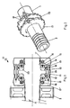
- the irreversibility device 10 is mounted at the end of a shaft 1 of which part 2, truncated and therefore not shown on the left of the figure 1, is threaded and cooperates, for example by means of balls, with a nut not shown.
- the device 10 is mounted symmetrically around a flange 11 central unit provided on the shaft 1. It comprises from each face of the flange 11 a friction disc 12, a ratchet wheel 13, members axial stop rollers 14 such as rollers or balls, and a plate stop 15, which is pressurized by preload springs 16 bearing on a bearing cover 17 in which the shaft 1 journals and a 17 'casing. Pawls 18 are associated with the wheels 13 to block them rotate in one direction and allow it in the other. The pawls 18 are mounted on pins 19 housed between the cover 17 and the casing 17 '.
- the ratchet wheels 13 are wedged on the shaft 1 and mounted, thus as the associated pawls, in opposition as shown in Figure 2.
- the torque induced by this load on the screw 2 is transmitted by friction from the flange 11 to the disc 12 (the one loaded by the axial component) and from the disc 12 to the ratchet wheel 13.
- the direction of the pawls was chosen so as to oppose the direction of the induced torque which is transmitted from the ratchet wheel 13 to the pawls 18 and to the case 17, thus ensuring irreversibility.
- the couples are considered in value absolute.
- the friction torque must always be greater than the induced couple. This is so by the choice of the mean radius of the disc, the contact materials and lubrication conditions.
- discs or more exactly friction rings 12 are centered on the shaft 1 by means of a shoulder 20 that it is necessary to provide near the foot of the collar 11, on both sides.
- the the small connecting radii imposed by this shoulder lead to embrittlement of this region of the collar.
- the discs 12 do not are not locked in rotation, so that friction is exerted indifferently both between the face of the facing flange and the wheel ratchet 13, which requires treating these two elements with surface hardness. This is not a major drawback for the ratchet wheel 13 whose face to which the rollers 14 bear must in any case be treated. In however, it is an additional operation for the collar which wish it could happen.
- the invention proposes to eliminate any friction. between the collar and the friction discs thanks to the immobilization, preferably from the outside, of said discs relative to the collar.
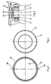
- the friction disc 12 is produced in the form of a ring whose outer radial edge 22 is grooved or toothed or has other types of relief intended to cooperate with complementary reliefs (such as grooves or teeth) formed on the inner edge 23 of a ring 24 holding intended to ensure the centering and the drive of the disc 12 by relative to the flange 11.
- the ring 24 has a flange 25 which comes to rest on the edge of the cylindrical periphery of the collar 11 and can be immobilized by two crimp tabs 26 taken in one recess 27 in the collar; a small torque is enough to retain the ring, since it is only a matter of systematically promoting friction on the face of the disc 12 in contact with the ratchet wheel 13.
- the disc 12 is thus centered from the outside, which gives the possibility of leaving a connection radius at the foot of the collar 11 allowing not to induce fragility, and to give the inner diameter of the chamfered edge of the annular disc 12 a dimension greater than that of the diameter of the shaft 1 in the vicinity of the collar 11.
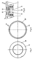
- the second embodiment of the invention shown in the Figures 6 to 8, is quite close to the previous one and also uses a ring centering and holding 24 of the disc 12, which cooperates with the latter by through conjugated recesses 28, 28 'which allow the passage of 29 tokens received and therefore blocked in recesses correspondents around the rim 11.
- the third embodiment of the invention shown in the Figures 9 and 10 do not use a ring to hold and center the disc 12: this function is directly fulfilled by rivets 30 (for example three) passing through equally spaced holes 31 on an intermediate circumference of the disc 12.
- the perimeter of the disc remaining free, can receive a ring 32 wear indicator, the thickness of which, measured from the plane of the face of the disc 12 in contact with the flange, is less than that of the disc itself.
- the ring 32 rubs on the ratchet wheel 13 and the friction torque increases considerably thanks to the choice of materials and the modification of the average radius of operation.
- the increase in torque in the direction of the helping load can go as far as blocking the system.
- this role of wear indicator is played by the retaining ring 24 which, like the show Figures 3 and 6, is also set back from the plane of the face, facing the ratchet wheel of the disc 12 not worn.
Description
L'invention concerne un dispositif d'irréversibilité lié à un système d'entraínement du type vis-écrou (notamment vis à billes) de façon à le rendre irréversible sous charge, afin d'assurer la sécurité de l'ensemble, à savoir le maintien en position en cas de rupture ou défaillance (ou glissement ou dévirement) dans le dispositif de commande (motoréducteur d'entraínement et frein d'arrêt).The invention relates to an irreversibility device linked to a screw-nut type drive system (especially ball screw) so as to make it irreversible under load, in order to ensure the safety of the assembly, know how to hold in position in case of breakage or failure (or sliding or deflection) in the control device (drive gearmotor and stop brake).
Le document US-A-4 569 241 fait connaítre un système vis à billes/écrou, dans lequel la vis et l'écrou d'une part, leurs éléments d'interface d'autre part, sont fabriqués séparément, puis assemblés ensuite, par exemple par soudure laser ou par soudure à faisceau d'électrons. Ce document ne montre toutefois pas de dispositif d'irréversibilité.Document US-A-4,569,241 discloses a system with balls / nut, in which the screw and nut on the one hand, their elements on the other hand, are manufactured separately, then assembled afterwards, for example by laser welding or by electron beam welding. This document does not however show an irreversibility device.
Le document US-A-5 088 581 concerne une roue libre à cliquets multiples constitués de lames flexibles, réalisée en plastique et fonctionnant jusqu'à 85°C, mais il ne montre pas de disque de frottement.Document US-A-5,088,581 relates to a freewheel with pawls multiple made of flexible blades, made of plastic and working up to 85 ° C, but it does not show a friction disc.
On connaít, notamment dans les applications à l'aéronautique, un dispositif d'irréversibilité pour système d'entraínement du type vis-écrou, comprenant en bout de l'arbre formant la vis, une collerette contre au moins une face de laquelle peuvent s'appuyer, axialement dans cet ordre, un disque annulaire de frottement, une roue libre à rochet bloquée dans un sens de rotation par un cliquet, au moins un organe roulant de butée axiale, et au moins un ressort de précharge s'appuyant sur le bâti, carter ou analogue dans lequel est monté l'arbre. En pratique, il est prévu un dispositif symétrique de part et d'autre de la collerette, et les deux roues à rochet ainsi que les cliquets sont montés en opposition, c'est-à-dire que le sens de rotation libre de l'une correspond au sens de blocage de l'autre. Ce dispositif connu dont on rappellera le fonctionnement plus loin en référence aux figures 1 et 2 annexées, assure bien l'irréversibilité requise.We know, especially in aeronautical applications, a irreversibility device for a screw-nut type drive system, comprising at the end of the shaft forming the screw, a flange against at least a face from which a disc can bear, axially in this order friction ring, a free wheel with ratchet locked in one direction rotation by a pawl, at least one rolling member with an axial stop, and at minus a preload spring resting on the frame, casing or the like in which mounted the tree. In practice, a symmetrical device is provided for on either side of the flange, and the two ratchet wheels and the pawls are mounted in opposition, i.e. the direction of free rotation of one corresponds to the blocking direction of the other. This known device including the operation will be recalled later with reference to FIGS. 1 and 2 attached, ensures the required irreversibility.
L'invention a pour but de perfectionner le dispositif connu et ce but est atteint en ce que le disque de frottement est immobilisé en rotation par rapport à la collerette de façon à supprimer tout frottement entre la collerette centrale et le disque de frottement. Le frottement intervient alors obligatoirement entre le disque et la roue à rochet, supprimant ainsi toute usure de la collerette centrale. Les seules pièces d'usure restent les disques de frottement et les roues à rochet, le frottement et l'usure de chaque disque étant localisés sur une seule face, celle qui est en contact avec la roue à rochet adjacente.The invention aims to improve the known device and this goal is achieved in that the friction disc is immobilized in rotation with respect to the collar so as to eliminate any friction between the central collar and friction disc. The friction then intervenes between the disc and the ratchet wheel, thus eliminating any wear of the central flange. The only wearing parts are the discs friction and ratchet wheels, friction and wear of each disc being located on one side only, that which is in contact with the wheel adjacent ratchet.
Avantageusement, le disque annulaire est immobilisé en rotation par une partie autre que son pourtour radialement intérieur. Le centrage du disque de frottement de cette manière permet d'optimiser le rayon de raccordement arbre-collerette centrale et, donc, de minimiser le coefficient de surcontrainte en pied de collerette. Autrement dit, le rayon de raccordement de la collerette n'est pas réduit par le centrage du disque de frottement.Advantageously, the annular disc is immobilized in rotation by a part other than its radially inner periphery. The centering of friction disc in this way optimizes the radius of central shaft-flange connection and, therefore, minimize the coefficient over-stress at the bottom of the flange. In other words, the radius of flange connection is not reduced by centering the disc friction.
Il est également avantageux de prévoir un témoin d'usure associé au disque et en retrait par rapport à la face dudit disque initialement en contact avec la roue à rochet, ce qui est possible selon l'invention puisque seule cette face est soumise à usure.It is also advantageous to provide an associated wear indicator to the disc and recessed from the face of said disc initially in contact with the ratchet wheel, which is possible according to the invention since only this face is subject to wear.
Le disque peut être centré et maintenu sur la collerette au moyen d'une bague extérieure. Celle-ci est bloquée en rotation sur le disque par des reliefs associés coopérant par complémentarité directe (par exemple par dents ou cannelures complémentaires) ou par complémentarité indirecte (par exemple par évidements en regard et pions interposés).The disc can be centered and held on the flange by means of an outer ring. This is blocked in rotation on the disc by associated reliefs cooperating by direct complementarity (for example by teeth or complementary grooves) or by indirect complementarity (by example by facing recesses and interposed pins).
La bague peut être sertie sur la collerette par une ou plusieurs pattes de sertissage, ou un bord de sertissage.The ring can be crimped onto the flange by one or more crimp tabs, or a crimping edge.
La bague peut aussi être fixée par des pions sur la collerette, ces mêmes pions pouvant servir au blocage de la bague sur le disque.The ring can also be fixed by pins on the collar, these same pins that can be used to lock the ring on the disc.
Le disque peut encore être maintenu et centré directement sur la collerette par des rivets.The disc can still be held and centered directly on the collar with rivets.
D'autres caractéristiques et avantages de l'invention ressortiront de la description suivante, se référant aux dessins annexés sur lesquels :
- la figure 1 montre en coupe longitudinale un dispositif d'irréversibilité de l'art antérieur pour ensemble vis-écrou,
- la figure 2 montre en perspective le détail des deux roues à rochet et des cliquets du dispositif de la figure 1,
- la figure 3 montre en demi-coupe longitudinale analogue à la figure 1 un premier mode de réalisation du dispositif d'irréversibilité conforme à l'invention,
- les figures 4 et 5 montrent en vue de bout respectivement un disque de frottement et une bague de maintien utilisés dans ce premier mode de réalisation,
- la figure 6 montre, en demi-coupe longitudinale, un second mode de réalisation du dispositif d'irréversibilité conforme à l'invention,
- les figures 7 et 8 montrent en vue de bout un disque de frottement et une bague de maintien utilisés dans ce deuxième mode de réalisation,
- la figure 9 montre, en demi-coupe longitudinale, un troisième mode de réalisation du dispositif d'irréversibilité conforme à l'invention,
- la figure 10 montre en vue de bout un disque de frottement utilisé dans ce troisième mode de réalisation.
- FIG. 1 shows in longitudinal section an irreversibility device of the prior art for a screw-nut assembly,
- FIG. 2 shows in perspective the detail of the two ratchet wheels and of the pawls of the device of FIG. 1,
- FIG. 3 shows in longitudinal half-section similar to FIG. 1 a first embodiment of the irreversibility device according to the invention,
- FIGS. 4 and 5 show in end view respectively a friction disc and a retaining ring used in this first embodiment,
- FIG. 6 shows, in longitudinal half-section, a second embodiment of the irreversibility device according to the invention,
- FIGS. 7 and 8 show an end view of a friction disc and a retaining ring used in this second embodiment,
- FIG. 9 shows, in longitudinal half-section, a third embodiment of the irreversibility device according to the invention,
- Figure 10 shows an end view of a friction disc used in this third embodiment.
On se référera aux figures 1 et 2 pour rappeler la structure générale et le fonctionnement d'un dispositif d'irréversibilité classique de l'art antérieur.We will refer to Figures 1 and 2 to recall the structure and the operation of a conventional irreversibility device prior art.
Le dispositif d'irréversibilité 10 est monté en bout d'un arbre 1
dont la partie 2, tronquée et donc non représentée sur la gauche de la figure
1, est filetée et coopère, par exemple par l'intermédiaire de billes, avec un
écrou non représenté. Un pignon de commande 3, entraíné par un motoréducteur
non représenté, est claveté ou solidarisé d'une autre manière sur
l'arbre 1 pour transmettre sa rotation à l'arbre 1 et à la vis 2, et entraíner en
translation l'écrou non représenté auquel est lié cinématiquement l'organe à
commander.The
Le dispositif 10 est monté symétriquement autour d'une collerette
11 centrale prévue sur l'arbre 1. Il comprend à partir de chaque face de la
collerette 11 un disque de frottement 12, une roue à rochet 13, des organes
roulants 14 de butée axiale tels que des rouleaux ou billes, et une plaque de
butée 15, laquelle est mise en pression par des ressorts de précharge 16
prenant appui sur un couvercle 17 de palier dans lequel tourillonne l'arbre 1
et un carter 17'. Des cliquets 18 sont associés aux roues 13 pour en bloquer
la rotation dans un sens et l'autoriser dans l'autre. Les cliquets 18 sont
montés sur des axes 19 logés entre le couvercle 17 et le carter 17'. The
Les roues à rochets 13 sont calées sur l'arbre 1 et montées, ainsi
que les cliquets associés, en opposition comme le montre la figure 2.The
Le fonctionnement classique de ce dispositif d'irréversibilité est rappelé ci-après.The classic operation of this irreversibility device is recalled below.
On distingue les notions de charges :
- "aidantes" ou "résistantes" qui sont liées au sens dans lequel on veut entraíner la vis en rotation, et qui sont en relation avec le fonctionnement dynamique du système,
- en "traction" ou en "compression", qui mettent en contact l'une ou l'autre face de la collerette avec l'un ou l'autre disque de frottement qui est en vis-à-vis.
- " helping " or " resistant " which are related to the direction in which we want to drive the screw in rotation, and which are related to the dynamic operation of the system,
- in " traction " or in " compression ", which bring one or the other face of the flange into contact with one or the other friction disc which is opposite.
Les roues à rochet et les butées à rouleaux :
- n'ont pas pour fonction principale d'assurer l'irréversibilité du système (qui pourrait être assurée en mettant directement en contact le disque de frottement avec la plaque de butée,
- mais de minimiser le couple d'entraínement (rôle des rouleaux) tout en
maintenant l'irréversibilité (rôle des rochets et des cliquets).
Le sens des rochets et cliquets est lié au sens d'inclinaison du filet de la vis (pas à droite ou pas a gauche).
- do not have the main function of ensuring the irreversibility of the system (which could be ensured by bringing the friction disc directly into contact with the stop plate,
- but minimize the drive torque (role of the rollers) while maintaining irreversibility (role of ratchets and pawls).
The direction of the ratchets and pawls is related to the direction of inclination of the screw thread (not to the right or not to the left).
Lorsqu'une charge est appliquée à l'écrou (traction ou compression),
la composante axiale de cette charge se transmet par la vis 2 sur
l'arbre 1 et pousse la collerette 11 contre l'un des disques de frottement 12 et
la roue adjacente 13.When a load is applied to the nut (traction or compression), the axial component of this load is transmitted by the screw 2 on the shaft 1 and pushes the
Le couple induit par cette charge sur la vis 2 se transmet par
friction de la collerette 11 au disque 12 (celui qui est chargé par la
composante axiale) et du disque 12 à la roue à rochet 13.The torque induced by this load on the screw 2 is transmitted by
friction from the
Le sens des cliquets a été choisi de façon à s'opposer au sens du
couple induit qui est transmis de la roue à rochets 13 aux cliquets 18 et au
boítier 17, assurant ainsi l'irréversibilité.The direction of the pawls was chosen so as to oppose the direction of the
induced torque which is transmitted from the
Quand on veut entraíner la vis 2 en rotation :
- si la charge est résistante (couple induit s'opposant au sens d'entraínement voulu), la roue à rochets tourne librement par rapport aux cliquets, et il n'y a pas de perte par frottement du disque pour entraíner la vis. Le couple appliqué au pignon 3 doit être supérieur ou égal au couple induit,
- si la charge est aidante (couple induit dans le sens de l'entraínement voulu), la roue à rochets est bloquée par les cliquets. Le couple appliqué au pignon 3 doit être supérieur ou égal à la différence entre le couple de frottement et le couple induit.
- if the load is resistant (induced torque opposing the desired direction of drive), the ratchet wheel turns freely relative to the pawls, and there is no friction loss of the disc to drive the screw. The torque applied to the pinion 3 must be greater than or equal to the induced torque,
- if the load is helping (torque induced in the direction of the desired drive), the ratchet wheel is blocked by the pawls. The torque applied to the pinion 3 must be greater than or equal to the difference between the friction torque and the induced torque.
Dans ce qui précède, les couples sont considérés en valeur absolue. D'autre part, le couple de frottement doit toujours être supérieur au couple induit. Il en est ainsi par le choix du rayon moyen du disque, des matériaux en contact et des conditions de lubrification.In the above, the couples are considered in value absolute. On the other hand, the friction torque must always be greater than the induced couple. This is so by the choice of the mean radius of the disc, the contact materials and lubrication conditions.
Cette structure et ce fonctionnement globalement connus sont intégralement repris dans la présente invention et on n'y reviendra pas.This structure and this generally known operation are fully incorporated into the present invention and will not be returned to.
Dans les dispositifs connus, les disques ou plus exactement
anneaux de frottement 12 sont centrés sur l'arbre 1 grâce à un épaulement 20
qu'il faut prévoir près du pied de la collerette 11, de part et d'autre. Les
faibles rayons de raccordement qu'impose cet épaulement entraínent une
fragilisation de cette région de la collerette. D'autre part, les disques 12 ne
sont pas bloqués en rotation, si bien que le frottement s'exerce
indifféremment à la fois entre la face de la collerette en regard et la roue à
rochet 13, ce qui oblige à traiter en dureté superficielle ces deux éléments.
Ceci n'est pas un inconvénient majeur pour la roue à rochet 13 dont la face
sur laquelle portent les rouleaux 14 doit de toute façon être traitée. En
revanche, c'est une opération supplémentaire pour la collerette dont on
souhaite pouvoir se passer.In known devices, discs or more exactly
friction rings 12 are centered on the shaft 1 by means of a
C'est pourquoi l'invention propose de supprimer tout frottement entre la collerette et les disques de frottement grâce à l'immobilisation, de préférence par l'extérieur, desdits disques par rapport à la collerette.This is why the invention proposes to eliminate any friction. between the collar and the friction discs thanks to the immobilization, preferably from the outside, of said discs relative to the collar.
Selon un premier mode de réalisation de l'invention représenté sur
les figures 3 à 5, le disque de frottement 12 est réalisé sous forme d'un
anneau dont le bord radial extérieur 22 est cannelé ou denté ou comporte
d'autres types de reliefs destinés à coopérer avec des reliefs complémentaires
(tels que cannelures ou dents) formés sur le bord intérieur 23 d'une bague 24
de maintien destinée à assurer le centrage et l'entraínement du disque 12 par
rapport à la collerette 11. A cet effet, la bague 24 comporte un rebord 25 qui
vient s'appuyer sur le bord du pourtour cylindrique de la collerette 11 et peut
être immobilisé grâce à deux pattes de sertissage 26 prises dans un
évidement 27 de la collerette ; un faible couple suffit à retenir la bague,
puisqu'il ne s'agit que de favoriser systématiquement le frottement sur la
face du disque 12 en contact avec la roue à rochet 13.According to a first embodiment of the invention shown in
Figures 3 to 5, the
Le disque 12 est ainsi centré de l'extérieur, ce qui donne la
possibilité de laisser au pied de la collerette 11 un rayon de raccordement
permettant de ne pas induire de fragilité, et de donner au diamètre intérieur
du bord chanfreiné du disque annulaire 12 une dimension supérieure à celle
du diamètre de l'arbre 1 au voisinage de la collerette 11.The
Le second mode de réalisation de l'invention représenté sur les
figures 6 à 8, est assez proche du précédent et utilise aussi une bague de
centrage et de maintien 24 du disque 12, qui coopère avec celui-ci par
l'intermédiaire d'évidements conjugués 28, 28' qui permettent le passage de
pions d'immobilisation 29 reçus et donc bloqués dans des évidements
correspondants du pourtour de la collerette 11.The second embodiment of the invention shown in the
Figures 6 to 8, is quite close to the previous one and also uses a ring
centering and holding 24 of the
Le troisième mode de réalisation de l'invention représenté sur les
figures 9 et 10, n'utilise pas de bague pour maintenir et centrer le disque
12 : cette fonction est directement remplie par des rivets 30 (par exemple
trois) passant dans des trous 31 équirépartis sur une circonférence intermédiaire
du disque 12. Le périmètre du disque, resté libre, peut recevoir un
anneau 32 témoin d'usure, dont l'épaisseur, mesurée à partir du plan de la
face du disque 12 en contact avec la collerette, est inférieure à celle du
disque lui-même. Quand le disque atteint sa cote minimale, l'anneau 32
frotte sur la roue à rochet 13 et le couple de friction augmente considérablement
grâce au choix de matériaux et à la modification du rayon moyen de
fonctionnement. L'augmentation du couple dans le sens de la charge aidante
peut aller jusqu'au blocage du système.The third embodiment of the invention shown in the
Figures 9 and 10, do not use a ring to hold and center the disc
12: this function is directly fulfilled by rivets 30 (for example
three) passing through equally spaced
On notera que dans les deux premiers modes de réalisation, ce
rôle de témoin d'usure est joué par la bague de maintien 24 qui, comme le
montrent les figures 3 et 6, est également en retrait par rapport au plan de la
face, tournée vers la roue à rochet du disque 12 non usé.It will be noted that in the first two embodiments, this
role of wear indicator is played by the retaining
Claims (10)
- Non-reversing device for a drive system of the screw-nut type, comprising, on the shaft (1) forming' the screw (2), a flange (11) against at least one face of which an annular friction disc (12), a ratchet free wheel (13) blocked in one direction of rotation by a pawl (18), at least one axial-stop rolling member (14) and at least one preload spring (16) resting against a casing (17), can rest, axially in this order, characterized in that the friction disc (12) is prevented from rotating with respect to the flange (11).
- Device according to Claim 1, characterized in that the annular disc (12) is prevented from rotating with respect to the flange (11) by a part other than its radially internal periphery.
- Device according to either one of the preceding claims, characterized by a wear indicator (24, 32) associated with the disc (12) and set back from that face of the said disc (12) that is initially in contact with the ratchet wheel (13).
- Device according to any one of the preceding claims, characterized in that the disc (12) is centered and held on the flange (11) by means of an external ring (24).
- Device according to Claim 4, characterized in that the ring (24) is blocked from rotating on the disc (12) by associated reliefs (22, 23, 24) which interact by being directly complementary (22, 23) or by being indirectly complementary (24).
- Device according to either one of Claims 4 or 5, characterized in that the ring (24) is crimped to the flange (11).
- Device according to either one of Claims 4 or 5, characterized in that the ring (24) is fixed to the flange (11) by pegs (29).
- Device according to any one of Claims 1 to 3, characterized in that the disc (12) is held and centered on the flange (11) by rivets (30).
- Device according to any one of the preceding claims, characterized in that the friction and wear of the disc (12) are localized on just one face, the one which is in contact with the ratchet wheel.
- Device according to any one of the preceding claims, characterized in that the fillet radius of the flange (11) is not reduced by the centering of the friction disc (12).
Applications Claiming Priority (3)
| Application Number | Priority Date | Filing Date | Title |
|---|---|---|---|
| FR9607296 | 1996-06-12 | ||
| FR9607296A FR2749896B1 (en) | 1996-06-12 | 1996-06-12 | IRREVERSIBILITY DEVICE WITH RATCHET WHEELS AND FRICTION DISC FOR A SCREW-NUT-TYPE DRIVE SYSTEM |
| PCT/FR1997/000875 WO1997047895A1 (en) | 1996-06-12 | 1997-05-16 | Non-reversing device with ratchet wheels and friction disk for screw-nut type driving system |
Publications (2)
| Publication Number | Publication Date |
|---|---|
| EP0904498A1 EP0904498A1 (en) | 1999-03-31 |
| EP0904498B1 true EP0904498B1 (en) | 2002-07-31 |
Family
ID=9492981
Family Applications (1)
| Application Number | Title | Priority Date | Filing Date |
|---|---|---|---|
| EP97925099A Expired - Lifetime EP0904498B1 (en) | 1996-06-12 | 1997-05-16 | Non-reversing device with ratchet wheels and friction disk for screw-nut type driving system |
Country Status (5)
| Country | Link |
|---|---|
| EP (1) | EP0904498B1 (en) |
| JP (1) | JP2000511998A (en) |
| DE (1) | DE69714437T2 (en) |
| FR (1) | FR2749896B1 (en) |
| WO (1) | WO1997047895A1 (en) |
Families Citing this family (2)
| Publication number | Priority date | Publication date | Assignee | Title |
|---|---|---|---|---|
| CN104948622A (en) * | 2015-07-01 | 2015-09-30 | 王丽 | Stop motion mechanism for threaded rotating column |
| WO2021185067A1 (en) * | 2020-03-17 | 2021-09-23 | 尹世和 | Multi-ratchet clutch |
Family Cites Families (4)
| Publication number | Priority date | Publication date | Assignee | Title |
|---|---|---|---|---|
| US4368652A (en) * | 1978-04-27 | 1983-01-18 | Caterpillar Tractor Co. | Friction assemblies for use in planetary transmissions |
| FR2544826A1 (en) * | 1983-04-20 | 1984-10-26 | Ratier Figeac Soc | IMPROVEMENTS IN VIS-NUT BALL SYSTEMS AND METHOD FOR MANUFACTURING SAME |
| FR2652393B3 (en) * | 1989-09-28 | 1991-08-23 | Mekhalian Robert | GROOVED LOCKING SYSTEM WITH LARGE BACK RADIUS AND LOW OVERSTRAIN IN THE TREE. |
| US5088581A (en) * | 1991-01-30 | 1992-02-18 | Eaton Corporation | One-way clutch |
-
1996
- 1996-06-12 FR FR9607296A patent/FR2749896B1/en not_active Expired - Lifetime
-
1997
- 1997-05-16 JP JP10501268A patent/JP2000511998A/en active Pending
- 1997-05-16 DE DE69714437T patent/DE69714437T2/en not_active Expired - Fee Related
- 1997-05-16 WO PCT/FR1997/000875 patent/WO1997047895A1/en active IP Right Grant
- 1997-05-16 EP EP97925099A patent/EP0904498B1/en not_active Expired - Lifetime
Also Published As
| Publication number | Publication date |
|---|---|
| FR2749896A1 (en) | 1997-12-19 |
| WO1997047895A1 (en) | 1997-12-18 |
| DE69714437D1 (en) | 2002-09-05 |
| EP0904498A1 (en) | 1999-03-31 |
| DE69714437T2 (en) | 2003-04-03 |
| JP2000511998A (en) | 2000-09-12 |
| FR2749896B1 (en) | 1998-08-07 |
Similar Documents
| Publication | Publication Date | Title |
|---|---|---|
| FR2610381A1 (en) | DIFFERENTIAL ASSEMBLY WITH LIMITED SLIDING | |
| FR2807488A1 (en) | Axial adjusting device for operating multi-plate clutch includes pressure disc rotationally secured by releasable anti-rotation means comprising axially movable bolt which engages in and releases from pawls | |
| WO2022106681A1 (en) | Electric drive device for a vehicle axle | |
| EP0340118B1 (en) | Continuous irreversible articulation | |
| EP0904498B1 (en) | Non-reversing device with ratchet wheels and friction disk for screw-nut type driving system | |
| EP1509705B1 (en) | Actuator with two motors, a differential reducer and a torque limiter | |
| FR2535254A1 (en) | INTEGRATED BRAKE WHEEL HUB | |
| FR2578761A1 (en) | BEARING DEVICE FOR A ROTATING SHAFT, IN PARTICULAR FOR ROLLER DRIVING SHAFTS OF ROLLING MILLS | |
| EP3379105B1 (en) | A roller gearing element | |
| FR2541393A1 (en) | DEVICE FOR AUTOMATICALLY CLAMPING GREEN OBLIQUE BEARINGS WITH A PAIR OF OTHER PAIRS IN A SET OF SMOOTH OR BEARING BEARINGS FOR A DRIVEN SHAFT | |
| FR2809463A1 (en) | FREE WHEEL COUPLING DRIVE TRANSMISSION ARRANGEMENT | |
| EP0366563B1 (en) | Self-locking differential | |
| EP4162157A1 (en) | Hydraulic machine comprising bearings for supporting the rotating component | |
| FR2849479A1 (en) | TORQUE RELEASE DEVICE | |
| EP1884673B1 (en) | Coupling system and braking system | |
| FR2751709A1 (en) | Roller bearing unit with conical rollers for circular shaft for machine tools | |
| FR3122227A1 (en) | Improved Duplicate Bearings | |
| FR3097021A1 (en) | REDUCER AND GEAR MOTOR FOR BRAKE WITH INTEGRATED CLUTCH | |
| FR3018328A3 (en) | DIFFERENTIAL FOR MOTOR VEHICLE WITH HOLDING DEVICE IN THE POSITION OF THE AXLE SATELLITE | |
| EP1509704B1 (en) | Actuator with torque limiter | |
| WO2001011232A1 (en) | Motor vehicle starter with friction drive | |
| EP4127503A1 (en) | Hydraulic machine comprising a stack of discs acted on by a push rod | |
| WO2020245534A1 (en) | Epicyclic step-down gear comprising at least one axial force transmission component which forms a radially eccentric force path | |
| EP4055300A1 (en) | Roller gear element | |
| FR2581151A1 (en) | Directly engaged automatic differential with autonomous selective coupling |
Legal Events
| Date | Code | Title | Description |
|---|---|---|---|
| PUAI | Public reference made under article 153(3) epc to a published international application that has entered the european phase |
Free format text: ORIGINAL CODE: 0009012 |
|
| 17P | Request for examination filed |
Effective date: 19981002 |
|
| AK | Designated contracting states |
Kind code of ref document: A1 Designated state(s): DE GB IT |
|
| GRAG | Despatch of communication of intention to grant |
Free format text: ORIGINAL CODE: EPIDOS AGRA |
|
| 17Q | First examination report despatched |
Effective date: 20011120 |
|
| GRAG | Despatch of communication of intention to grant |
Free format text: ORIGINAL CODE: EPIDOS AGRA |
|
| GRAH | Despatch of communication of intention to grant a patent |
Free format text: ORIGINAL CODE: EPIDOS IGRA |
|
| GRAH | Despatch of communication of intention to grant a patent |
Free format text: ORIGINAL CODE: EPIDOS IGRA |
|
| GRAA | (expected) grant |
Free format text: ORIGINAL CODE: 0009210 |
|
| AK | Designated contracting states |
Kind code of ref document: B1 Designated state(s): DE GB IT |
|
| REG | Reference to a national code |
Ref country code: GB Ref legal event code: FG4D Free format text: NOT ENGLISH |
|
| GBT | Gb: translation of ep patent filed (gb section 77(6)(a)/1977) |
Effective date: 20020731 |
|
| REF | Corresponds to: |
Ref document number: 69714437 Country of ref document: DE Date of ref document: 20020905 |
|
| PLBE | No opposition filed within time limit |
Free format text: ORIGINAL CODE: 0009261 |
|
| STAA | Information on the status of an ep patent application or granted ep patent |
Free format text: STATUS: NO OPPOSITION FILED WITHIN TIME LIMIT |
|
| 26N | No opposition filed |
Effective date: 20030506 |
|
| PGFP | Annual fee paid to national office [announced via postgrant information from national office to epo] |
Ref country code: GB Payment date: 20040512 Year of fee payment: 8 |
|
| PG25 | Lapsed in a contracting state [announced via postgrant information from national office to epo] |
Ref country code: IT Free format text: LAPSE BECAUSE OF NON-PAYMENT OF DUE FEES Effective date: 20050516 Ref country code: GB Free format text: LAPSE BECAUSE OF NON-PAYMENT OF DUE FEES Effective date: 20050516 |
|
| PGFP | Annual fee paid to national office [announced via postgrant information from national office to epo] |
Ref country code: DE Payment date: 20050701 Year of fee payment: 9 |
|
| GBPC | Gb: european patent ceased through non-payment of renewal fee |
Effective date: 20050516 |
|
| PG25 | Lapsed in a contracting state [announced via postgrant information from national office to epo] |
Ref country code: DE Free format text: LAPSE BECAUSE OF NON-PAYMENT OF DUE FEES Effective date: 20061201 |