EP0903906B1 - Devices for adaptive control of transport-layer connections between mobile and fixed hosts - Google Patents
Devices for adaptive control of transport-layer connections between mobile and fixed hosts Download PDFInfo
- Publication number
- EP0903906B1 EP0903906B1 EP98307677A EP98307677A EP0903906B1 EP 0903906 B1 EP0903906 B1 EP 0903906B1 EP 98307677 A EP98307677 A EP 98307677A EP 98307677 A EP98307677 A EP 98307677A EP 0903906 B1 EP0903906 B1 EP 0903906B1
- Authority
- EP
- European Patent Office
- Prior art keywords
- radio
- terminal device
- radio terminal
- unit
- transport layer
- Prior art date
- Legal status (The legal status is an assumption and is not a legal conclusion. Google has not performed a legal analysis and makes no representation as to the accuracy of the status listed.)
- Expired - Lifetime
Links
Images


Classifications
-
- H—ELECTRICITY
- H04—ELECTRIC COMMUNICATION TECHNIQUE
- H04L—TRANSMISSION OF DIGITAL INFORMATION, e.g. TELEGRAPHIC COMMUNICATION
- H04L69/00—Network arrangements, protocols or services independent of the application payload and not provided for in the other groups of this subclass
- H04L69/16—Implementation or adaptation of Internet protocol [IP], of transmission control protocol [TCP] or of user datagram protocol [UDP]
-
- H—ELECTRICITY
- H04—ELECTRIC COMMUNICATION TECHNIQUE
- H04L—TRANSMISSION OF DIGITAL INFORMATION, e.g. TELEGRAPHIC COMMUNICATION
- H04L69/00—Network arrangements, protocols or services independent of the application payload and not provided for in the other groups of this subclass
- H04L69/08—Protocols for interworking; Protocol conversion
-
- H—ELECTRICITY
- H04—ELECTRIC COMMUNICATION TECHNIQUE
- H04L—TRANSMISSION OF DIGITAL INFORMATION, e.g. TELEGRAPHIC COMMUNICATION
- H04L69/00—Network arrangements, protocols or services independent of the application payload and not provided for in the other groups of this subclass
- H04L69/16—Implementation or adaptation of Internet protocol [IP], of transmission control protocol [TCP] or of user datagram protocol [UDP]
- H04L69/163—In-band adaptation of TCP data exchange; In-band control procedures
-
- H—ELECTRICITY
- H04—ELECTRIC COMMUNICATION TECHNIQUE
- H04L—TRANSMISSION OF DIGITAL INFORMATION, e.g. TELEGRAPHIC COMMUNICATION
- H04L69/00—Network arrangements, protocols or services independent of the application payload and not provided for in the other groups of this subclass
- H04L69/16—Implementation or adaptation of Internet protocol [IP], of transmission control protocol [TCP] or of user datagram protocol [UDP]
- H04L69/169—Special adaptations of TCP, UDP or IP for interworking of IP based networks with other networks
-
- H—ELECTRICITY
- H04—ELECTRIC COMMUNICATION TECHNIQUE
- H04L—TRANSMISSION OF DIGITAL INFORMATION, e.g. TELEGRAPHIC COMMUNICATION
- H04L69/00—Network arrangements, protocols or services independent of the application payload and not provided for in the other groups of this subclass
- H04L69/30—Definitions, standards or architectural aspects of layered protocol stacks
- H04L69/32—Architecture of open systems interconnection [OSI] 7-layer type protocol stacks, e.g. the interfaces between the data link level and the physical level
- H04L69/322—Intralayer communication protocols among peer entities or protocol data unit [PDU] definitions
- H04L69/326—Intralayer communication protocols among peer entities or protocol data unit [PDU] definitions in the transport layer [OSI layer 4]
-
- H—ELECTRICITY
- H04—ELECTRIC COMMUNICATION TECHNIQUE
- H04W—WIRELESS COMMUNICATION NETWORKS
- H04W80/00—Wireless network protocols or protocol adaptations to wireless operation
- H04W80/06—Transport layer protocols, e.g. TCP [Transport Control Protocol] over wireless
-
- H—ELECTRICITY
- H04—ELECTRIC COMMUNICATION TECHNIQUE
- H04W—WIRELESS COMMUNICATION NETWORKS
- H04W92/00—Interfaces specially adapted for wireless communication networks
- H04W92/02—Inter-networking arrangements
-
- H—ELECTRICITY
- H04—ELECTRIC COMMUNICATION TECHNIQUE
- H04W—WIRELESS COMMUNICATION NETWORKS
- H04W80/00—Wireless network protocols or protocol adaptations to wireless operation
- H04W80/04—Network layer protocols, e.g. mobile IP [Internet Protocol]
Definitions
- the present invention relates to a gateway device, a radio base station device, a router device and a radio terminal device, which are to be used in radio communications utilizing the transport layer.
- TCP Transmission Control Protocol
- a TCP segment loss in the wire communications implies the congestion of a network so that TCP is designed to avoid the congestion by lowering a data transmission rate when the segment loss is detected. For this reason, the TCP segment loss due to a radio section error and a handoff will also be interpreted as the congestion so that the congestion avoidance operations will be executed more than necessary and as a result the throughput will be lowered more than necessary.
- a keep-alive packet will be transmitted by a server terminal in which a keep-alive option is set valid. If there is no response to this keep-alive packet which is an inspection packet, the transmission of this keep-alive packet will be continued at 75 seconds interval, but when ten consecutive trials fail, it is judged that a terminal on the client side is inactive and the connection will be disconnected.
- the radio terminal and a gateway device for relaying the transport layer protocol cannot directly ascertain the radio communication state of the radio terminal that terminates the transport layer connection, so that there has been a problem that it is impossible realize the adaptive control of the transport layer connection (such as a dynamic change of a segment size) according to the radio communication state or property.
- I-TCP Indirect TCP for Mobile Hosts
- I-TCP Indirect TCP for Mobile Hosts
- This document again describes an implementation of I-TCP which utilises routers to provide communication between mobile devices and devices on a fixed network.
- the system describes handling the problems related to mobility and unreliability of wireless links within the wireless link so as to avoid modification of the software on fixed wired link hosts.
- US-5,159,596 describes a mobile communication system including a gateway exchange unit for exchanging communications between mobile radio units and the radio base stations and for connecting the radio base stations to a public switched telephone network.
- US-5,457,680 describes a system for managing the communication of data packets between a mobile data radio terminal and a plurality of fixed base stations. The system includes determining which base station is providing better signal measurement data and establishing a channel with the better base station.
- the present invention provides a gateway device, a radio base station device, a router device, and a radio terminal device for this communication scheme.
- a gateway device for relaying a transport layer connection terminated at a radio terminal device at a transport layer via a router device for carrying out data transfer between the radio terminal device and a wire terminal device, the gateway device being provided separately from the router device in correspondence to transport layer connections terminated at radio terminal devices and comprising:
- a router device being connected with a plurality of radio base station devices for accommodating a radio terminal device located within radio service areas and a wire network to which a wire terminal device is connected, for carrying out data transfer between the radio terminal device and the wire terminal device by utilizing a plurality of gateway devices for relaying a transport layer connection terminated at the radio terminal device at a transport layer, the router device characterized by:
- a radio base station device comprising:
- Fig. 1 shows an exemplary configuration of a network using communication devices (gateway device, router device, base station device) of the present invention.
- This network of Fig. 1 comprises a wire network 1101, wire terminals 1001 to 1003 connected to the wire network 1101, gateway devices 501 to 503, base station devices 1401 to 1406 covering radio service areas 1701 to 1706 respectively, radio terminal devices 1801 to 1804 which carry out communications while moving through these radio service areas 1701 to 1706, and a router device 1301 for interconnecting the wire network 1101, the gateway devices 501 to 503 and the base station devices 1401 to 1406.
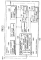
- Fig. 2 shows an exemplary configuration of a base station device 1400 that can be used for each one of the base station devices 1401-1406 of Fig. 1.
- This base station device 1400 of Fig. 2 comprises a control unit 1500 having a signal strength change notification unit 1501, a BER (Bit Error Rate) change notification unit 1502 and a terminal movement control unit 1503; a radio transmission and reception unit 1600 having a receiver 1601 that contains a signal strength measurement unit 1604, a transmitter 1602, and a duplexer 1603 for enabling the receiver 1601 and the transmitter 1602 to commonly use an antenna 1605; a BER measurement unit 1606; an IP unit 210 having an IP input unit 211 and an IP output unit 212; and an IF (interface) unit 140 having an IF input unit 141 and an IF output unit 142.
- solid lines indicate data flows while dashed lines indicate control flows.
- the signal strength measurement unit 1604 measures a received signal strength for each radio terminal device 1801-1804, and notifies the measured signal strength regularly to the control unit 1500.
- the BER measurement unit 1606 measures the BER of signals flowing from the receiver 1601 to the IF output unit 142 for each radio terminal device 1801-1804, and notifies the measured BER regularly to the control unit 1500.
- the received signal strength and the BER are Just examples of information indicating a radio communication state between the radio terminal device and the radio base station device.
- the signal strength change notification unit 1501 of the control unit 1500 gives a message to the IP output unit 212, where the message has the router device 1301 as its destination and contains the received signal strength for each radio terminal device 1801-1804 obtained by the signal strength measurement unit 1604 and an identifier of a corresponding radio terminal device 1801-1804.
- the BER change notification unit 1502 of the control unit 1500 gives a message to the IP output unit 212, where the message has the router device 1301 as its destination and contains the BER for each radio terminal device 1801-1804 obtained by the BER measurement unit 1606 and an identifier of a corresponding radio terminal device 1801-1804.
- an IP address allocated to each radio terminal device 1801-1804 can be used, for example.
- a new ICMP (Internet Control Message Protocol) message may be defined. Namely, as an ICMP message for notifying an information indicating the radio communication state such as the received signal strength or the BER and the identifier of the radio terminal device, new type and code can be allocated and a format for information content (the received signal strength or the BER and the identifier of the radio terminal device) can be defined. This message may be notified from the base station device 1400 to the router device 1301 either regularly or only when the received signal strength or the BER exceeds a prescribed threshold.
- ICMP Internet Control Message Protocol
- Fig. 3 shows an exemplary configuration of the router device 1301 of Fig. 1.
- This router device 1301 of Fig. 3 generally comprises a plurality (only two are shown in Fig. 3) of wire IF units 100, 110 which are connected with the wire network 1101 and the gateway devices 501-503 respectively; a plurality (only two are shown in Fig. 3) of radio IF units 120, 130 which are connected with the base station devices 1401-1406 respectively; and an IP unit 200.
- Each wire IF unit 100, 110 comprises a wire IF input unit 101, 111 and a wire IF output unit 102, 112, while each radio IF unit 120, 130 comprises a radio IF input unit 121, 131 and a radio IF output unit 122, 132.
- the IP unit 200 comprises an IP input unit 201 having a datagram filter 205, an IP output unit 202, an IP relay unit 203 storing a correspondence table 206, and a mobile control unit 204.
- the message (ICMP message for example) for notifying the radio communication state that is transmitted from the base station device reaches to the IP input unit 201 via the radio IF input unit 121 or 131. Then, the IP input unit 201 recognizes that this message is an ICMP message for notifying the radio communication state (which can be identified by the type and code of ICMP) by using the datagram filter 205. Then, the IP input unit 201 also recognizes that it is a message (IP datagram) to be transferred to one of the gateway devices 501-503 which is relaying the transport layer connection terminated at the radio terminal device as identified by the identifier contained in that message, and gives it to the IP relay unit 203.
- IP datagram IP datagram
- the correspondence table 206 of the IP relay unit 203 indicates a correspondence between IP addresses of the radio terminal devices 1801-1804 and IP addresses of the gateway devices 501-503 which are relaying the transport layer connections terminated at the radio terminal devices 1801-1804.
- This correspondence can be established as follows, for example.
- the terminal movement control unit 1503 of the base station device 1401-1406 notifies to the mobile control unit 204 of the router device 1301 that the radio terminal device 1801-1804 is newly discovered in one of the radio service areas 1701-1706 (including the case where the radio terminal device turns the power on there)
- the mobile control unit 204 sets that radio terminal device in correspondence to one of the gateway devices 501-503 according to a prescribed rule.
- the IP relay unit 203 obtains the IP address of one of the gateway devices 501-503 that corresponds to the IP address of the radio terminal device contained in that message, from the correspondence table 206. Then, the IP relay unit 203 writes this IP address of the gateway device into an IP header of that message as a new destination of that message, and gives this message to the IP output unit 202.
- the IP output unit 202 then transmits this message to one of the gateway devices 501-503 via the wire IF output unit 102 or 112 that corresponds to the destination of that message.
- the destination of the message entered into the IP input unit 201 is an address of the router device 1301 so that it should be given to the upper layer normally. Consequently, the above described processing at the IP relay unit 203 (the processing for specifying a gateway device that corresponds to the radio terminal device of the identifier contained in that message by referring to the correspondence table 206 and transferring that message to that identified gateway device) may be carried out at the upper layer. Namely, it is possible to provide a function for processing that message in the upper layer and give that message to this function instead of the IP relay unit 203.
- Fig. 4 shows an exemplary configuration of a gateway device 500 that can be used for each one of the gateway devices 501-503 of Fig. 1.
- This gateway device 500 of Fig. 4 generally comprises an IF unit 150, an IP unit 220, a TCP unit 300, a TCP relay unit 310 and a radio TCP unit 320.
- the IF unit 150 comprises an IF input unit 151 and an IF output unit 152 which are connected to the router device 1301.
- the IP unit 220 comprises an IP input unit 221 having a datagram filter 224, an IP output unit 222, an IP relay unit 223, and a radio communication state receiving processing unit 225.
- the TCP unit 300 comprises a TCP input unit 301 having a segment filter 303 and a TCP output unit 302.
- the radio TCP unit 320 comprises a radio TCP input unit 321 having a segment filter 323, a radio TCP output unit 322, and a radio communication state adaptation control unit 324.
- the TCP relay unit 310 comprises a converter 311 for converting the radio transport layer protocol into the wire transport layer protocol, and a converter 312 for converting the wire transport layer protocol into the radio transport layer protocol.
- the message transferred from the router device 1301 to the gateway device 500 reaches to the IP input unit 221 through the IF input unit 151 of the gateway device 500.
- the IP input unit 221 recognizes that the entered message is a message for notifying the radio communication state by using the datagram filter 224, and sends this message to the radio communication state receiving processing unit 225.
- the radio communication state receiving processing unit 225 extracts an identifier (IP address) of the radio terminal device and an information regarding the radio communication state (such as the received signal strength or the BER for example) contained in the message, and notifies them to the radio TCP unit 320.
- IP address an identifier
- the radio communication state receiving processing unit 225 extracts an identifier (IP address) of the radio terminal device and an information regarding the radio communication state (such as the received signal strength or the BER for example) contained in the message, and notifies them to the radio TCP unit 320.
- the radio communication state adaptation control unit 324 of the radio TCP unit 320 then adaptively changes the radio TCP operation according to that information regarding the radio communication state. For example, the maximum size of a radio TCP segment to be transmitted is made smaller when the BER becomes higher than a prescribed threshold (or when the received signal strength becomes lower than a prescribed threshold), and the maximum size of a radio TCP segment to be transmitted is made larger when the BER becomes lower than a prescribed threshold (or when the received signal strength becomes higher than a prescribed threshold).
- Such a transport layer connection control command (a command for changing the size of a TCP segment, for example) is applied to the radio TCP output unit 322 such that each radio TCP segment that is subsequently transmitted from the converter 312 of the TCP relay unit 310 will have its size changed to the size determined by the radio communication state adaptation control unit 324 at a time of output from the radio TCP output unit 322, and transmitted to the base station device through the IP output unit 222 and the IF output unit 152.
- the first embodiment is directed to the case where the router device 1301 sets the radio terminal device identified by the identifier contained in the message in correspondence to one of the plurality of gateway devices according to the message for notifying the radio communication state that is transmitted from one of the base station devices 1401-1406 to the router device 1301 (the case of specifying a gateway device that is a transfer target of the message for notifying the radio communication state).
- this second embodiment is directed to the case where the base station device 1401-1406 sets the radio terminal device in correspondence to one of the plurality of gateway devices.
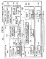
- Fig. 5 shows an exemplary configuration of a base station device 1400 according to this second embodiment, that can be used for each one of the base stations 1401-1406 of Fig. 1.
- the elements that are substantially the same as those of Fig. 2 are given the same reference numerals in Fig. 5 and only differences from Fig. 2 will be described. Namely, the configuration of Fig. 5 differs from that of Fig. 2 in that the control unit 1500 has a correspondence table 1504.
- the correspondence table 1504 indicates a correspondence between IP addresses of the radio terminal devices 1801-1804 and IP addresses of the gateway devices 501-503 which are relaying the transport layer connections terminated at the radio terminal devices 1801-1804.
- This correspondence can be established as follows, for example.
- the router device 1301 already has this correspondence in the correspondence table 206 by the procedure described in the first embodiment.
- the mobile control unit 204 of the router device 1301 searches for an identifier (IP address) of one of the gateway devices 501-503 that is relaying the transport layer connection terminated at the radio terminal device as identified by the identifier (IP address) contained in that received message, by referring to the correspondence table 206. Then, the mobile control unit 204 of the router device 1301 transmits a prescribed response message containing this searched out identifier of the gateway device to the base station device that transmitted the message for noting the discovery of the radio terminal device earlier.
- IP address IP address
- the response message from the router device 1301 is received through the IF input unit 141 and the IP input unit 211, and the identifier of the gateway device is extracted from that response message. Then, the terminal movement control unit 1503 registers a correspondence between that identifier of the gateway device and that radio terminal device in the correspondence table 1504.
- the signal strength change notification unit 1501 of the control unit 1500 generates a message containing the received signal strength for that radio terminal device obtained by the signal strength measurement unit 1604 and the identifier of that radio terminal device, and gives this message to the IP output unit 212.
- the signal strength change notification unit 1501 searches out the identifier (IP address) of the gateway device that corresponds to the identifier of that radio terminal device from the correspondence table 1504, and sets it as a destination of the generated message.
- the BER change notification unit 1502 of the control unit 1500 generates a message containing the BER for that radio terminal device obtained by the BER measurement unit 1606 and the identifier of that radio terminal device, and gives this message to the IP output unit 212.
- the BER change notification unit 1502 searches out the identifier (IP address) of the gateway device that corresponds to the identifier of that radio terminal device from the correspondence table 1504, and sets it as a destination of the generated message.
- the router device 1301 When such a message is transmitted to the router device 1301 through the IP output unit 212 and the IF output unit 142, the router device 1301 handles it similarly as the usual IP packet by carrying out the routing to one of the gateway devices 501-503 that is specified by the IP address contained in the IP packet.
- the operation of the gateway device 501-503 that received this message is the same as in the first embodiment described above.
- the first and second embodiments are directed to the case where the gateway device 501-503 carries out the radio TCP control by utilizing the message for notifying the radio communication state that is transmitted from the base station device 1401-1406 or the router device 1301.
- this third embodiment is directed to the case of utilizing a home location register to be provided in a radio network will be described.
- the base station device has a configuration of Fig. 5 described above.
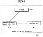
- Fig. 6 shows an exemplary configuration of the home location register 600, which comprises a control unit 601, a radio state information management table 602, and a transmission and reception unit 603.
- Fig. 7 shows an exemplary content of the radio state information management table 602 managed by the home location register 600 of Fig. 6.
- the home location register 1303 manages a registered radio terminal and a base station that accommodates that radio terminal, and an information on a radio communication state between that radio terminal and that base station, using the table content as shown in Fig. 7 in the radio state information management table 602.
- the signal strength change notification unit 1501 of the control unit 1500 in the radio base station 1401-1406 generates a message containing the received signal strength for that radio terminal device obtained by the signal strength measurement unit 1604 and the identifier of that radio terminal device, and gives this message to the IP output unit 212.
- the signal strength change notification unit 1501 searches out the identifier (IP address) of that radio terminal device from the correspondence table 1504, and sets it as a part of data of the generated message. Also, the address of the home location register 600 is set as a destination address of the generated message.
- the BER change notification unit 1502 of the control unit 1500 generates a message containing the BER for that radio terminal device obtained by the BER measurement unit 1606 and the identifier of that radio terminal device, and gives this message to the IP output unit 212.
- the BER change notification unit 1502 searches out the identifier (IP address) of that radio terminal device from the correspondence table 1504, and sets it as a part of data of the generated message. Also, the address of the home location register 600 is set as a destination address of the generated message.
- the router device 1301 When such a message is transmitted to the router device 1301 through the IP output unit 212 and the IF output unit 142, the router device 1301 handles it similarly as the usual IP packet by carrying out the routing to the home location register 600 that is specified by the IP address contained in the IP packet.
- the control unit 601 of the home location register 600 takes out the radio terminal identifier and the radio communication state information from that message, and add them to the radio state information management table 602.
- the control unit 601 takes out the radio communication state of the corresponding radio terminal from the radio state information management table 602, forms a packet containing that information, and transmits that packet to the gateway device 501-503.
- the operation of the gateway device 501-503 that received this message is the same as in the first embodiment described above.
- the wire terminal 1001 connected to the wire network 1101 is carrying out communications with the radio terminal 1802 through the gateway device 501.
- the radio communication state adaptation control unit 324 in the radio TCP unit 320 of the gateway device 501 sets the radio keep-alive timer (not shown).
- the time set for this timer is sufficiently shorter than the keep-alive timer usually utilized in the TCP layer.
- the radio communication state adaptation control unit 324 carries out the operation to disconnect a connection between the wire terminal 1001 and the radio terminal 1802.
- the radio communication state adaptation control unit 324 transmits a packet requesting the radio terminal 1802 to carry out the processing for disconnecting the connection.
- the radio communication state adaptation control unit 324 resets the radio keep-alive timer, while transmitting a signal requesting the radio TCP output unit 322 to reset a re-transmission timer 325 and re-transmit a re-transmission packet immediately.
- Fig. 8 shows an exemplary configuration of a radio terminal device 1800 that can be used for each one of the radio terminal devices 1801-1804 of Fig. 1.
- This radio terminal device 1800 of Fig. 8 comprises a communication state monitoring unit 704 and a TCP unit 700 that contains a control unit 701 for controlling the TCP layer, a TCP output unit 702, a TCP output unit 703, and a radio keep-alive timer 705.
- the communication state monitoring unit 704 is monitoring whether a link to the base station is connected or not, and notifies the monitored state to the control unit 701 of the TCP unit 700.
- the wire terminal 1001 connected to the wire network 1101 is carrying out communications with the radio terminal 1802 through the gateway device 501.
- the control unit 701 in the TCP unit 700 of the radio terminal device 1802 sets the radio keep-alive timer 705.
- the time set for this timer is sufficiently shorter than the keep-alive timer usually utilized in the TCP layer.
- the control unit 701 carries out the operation to disconnect the connection with the wire terminal 1001.
- the control unit 701 transmits a packet requesting the gateway device 501 to carry out the processing for disconnecting the connection.
- the control unit 701 resets the radio keep-alive timer 705, while transmitting a signal requesting the TCP output unit 702 to reset a re-transmission timer 706 and re-transmit a re-transmission packet immediately.
- the present invention it is possible to improve the performance of communications utilizing the transport layer connection provided via a radio network, by enabling a control of the transport layer connection according to the radio communication state and property of the radio terminal, without changing implementation of the transport layer of a terminal connected to a wire network.
Landscapes
- Engineering & Computer Science (AREA)
- Computer Networks & Wireless Communication (AREA)
- Signal Processing (AREA)
- Computer Security & Cryptography (AREA)
- Mobile Radio Communication Systems (AREA)
- Data Exchanges In Wide-Area Networks (AREA)
Description
- The present invention relates to a gateway device, a radio base station device, a router device and a radio terminal device, which are to be used in radio communications utilizing the transport layer.
- In recent years there are increasing demands for carrying out not just speech communications but also data communications by radio. TCP (Transmission Control Protocol) is widely used as a reliable transport layer protocol in the wire data communications, but the direct application of this protocol to radio communications causes the following problems.
- A TCP segment loss in the wire communications implies the congestion of a network so that TCP is designed to avoid the congestion by lowering a data transmission rate when the segment loss is detected. For this reason, the TCP segment loss due to a radio section error and a handoff will also be interpreted as the congestion so that the congestion avoidance operations will be executed more than necessary and as a result the throughput will be lowered more than necessary.
- In order to resolve this problem, there is a proposition to use the usual TCP in a wire network and the radio transport layer in a radio network and relay communications at a border between the wire network and the radio network. For example, "selective ack" is used for a high segment loss rate on the radio network side. Namely, this is a scheme for resolving the congestion problem in such a way that a data loss in the radio section is not regarded as the congestion and a re-transmission is carried out without lowering the transmission rate.
- Also, in TCP, when an idle connection state, i.e., a state where no response comes from a terminal on one side and no response comes a terminal on the other side as well, is continued for two hours, a keep-alive packet will be transmitted by a server terminal in which a keep-alive option is set valid. If there is no response to this keep-alive packet which is an inspection packet, the transmission of this keep-alive packet will be continued at 75 seconds interval, but when ten consecutive trials fail, it is judged that a terminal on the client side is inactive and the connection will be disconnected.
- As described, in the case of carrying out communications between a radio terminal device accommodated in a radio network and a wire terminal device accommodated in a wire network, the radio terminal and a gateway device for relaying the transport layer protocol cannot directly ascertain the radio communication state of the radio terminal that terminates the transport layer connection, so that there has been a problem that it is impossible realize the adaptive control of the transport layer connection (such as a dynamic change of a segment size) according to the radio communication state or property.
- The paper entitled "Implementation and Performance Evaluation of Indirect TCP" by Bakre A.V. et al in IEEE Transactions on Computers, US, IEEE Inc. New York, vol. 46, no. 3, 1 March 1997, pages 260-278, describes the problems of interfacing wireless and wired networks and presents an implementation and performance of evaluation of I-TCP. This involves establishing a connection in the wired part of the I-TCP connection and a connection in the wireless part.
- The paper entitled "I-TCP; Indirect TCP for Mobile Hosts" by Ajay Bakre et al in proceedings of the International Conference on Distributed Computing Systems, US, Los Alamitos, IEEE Comp. Soc. Press, vol. 15, 30 May 1995, pages 136-143, describes the problems of IP based solutions where wireless and wired networks are both used. This document again describes an implementation of I-TCP which utilises routers to provide communication between mobile devices and devices on a fixed network. The system describes handling the problems related to mobility and unreliability of wireless links within the wireless link so as to avoid modification of the software on fixed wired link hosts.
- US-5,159,596 describes a mobile communication system including a gateway exchange unit for exchanging communications between mobile radio units and the radio base stations and for connecting the radio base stations to a public switched telephone network. US-5,457,680 describes a system for managing the communication of data packets between a mobile data radio terminal and a plurality of fixed base stations. The system includes determining which base station is providing better signal measurement data and establishing a channel with the better base station.
- It is therefore an object of the present invention to provide a communication scheme for improving the performance of communications utilizing the transport layer connection provided via a radio network, by enabling a control of the transport layer connection according to the radio communication state and property of the radio terminal, without changing implementation of the transport layer of a terminal connected to a wire network, so as to resolve the above described problems that arise when a reliable transport layer protocol is applied to a radio network.
- Specifically, the present invention provides a gateway device, a radio base station device, a router device, and a radio terminal device for this communication scheme.
- According to one aspect of the present invention there is provided a gateway device for relaying a transport layer connection terminated at a radio terminal device at a transport layer via a router device for carrying out data transfer between the radio terminal device and a wire terminal device, the gateway device being provided separately from the router device in correspondence to transport layer connections terminated at radio terminal devices and comprising:
- a transfer unit configured to transmit and receive respective control information; and
- a conversion unit configured to bidirectionally convert a first transport layer protocol used for communications within a radio network and a second transport layer protocol used for communications within a wire network, in a case of carrying out communications between the radio terminal device accommodated in the radio network and wire terminal device accommodated in the wire network; characterized by
- a control unit configured to adaptively control an operation characteristic of a connection in the first transport layer protocol according to an information regarding a radio communication state of the radio terminal device.
- According to another aspect of the present invention there is provided a router device, being connected with a plurality of radio base station devices for accommodating a radio terminal device located within radio service areas and a wire network to which a wire terminal device is connected, for carrying out data transfer between the radio terminal device and the wire terminal device by utilizing a plurality of gateway devices for relaying a transport layer connection terminated at the radio terminal device at a transport layer, the router device characterized by:
- a correspondence setting unit configured to set the radio terminal device in correspondence to one of a plurality of gateway devices for adaptively controlling an operation characteristic of a transport layer connection for the radio communications of the radio mobile device according to a radio communication state of the radio terminal device; and
- a transfer unit configured to receive from one radio base station in whose radio service area the radio terminal device is located a packet that contains at least an identifier of the radio terminal device and an information regarding the radio communication state of the radio terminal device, and transfer said packet to a gateway device that is set in correspondence to the radio terminal device by the correspondence setting unit.
- According to another aspect of the present invention there is provided a radio base station device, comprising:
- a processing unit configured to carry out a base station processing necessary in accommodating a radio terminal device located in a radio service area:
- a notification unit configured to notify an information regarding a radio communication state of the radio terminal device located in the radio service area, to one of a router, a gateway, and a home location register; and characterized by a correspondence setting unit configured to set the radio terminal device located in the radio service area in correspondence to one of a plurality of gateway devices for adaptively controlling an operation characteristic of a transport layer connection for radio communications of the radio terminal device according to the radio communication state of the radio terminal device.
- Other features and advantages of the present invention will become apparent from the following description taken in conjunction with the accompanying drawings.
-
- Fig. 1 is a schematic diagram showing an exemplary configuration of a network using communication devices of the present invention.
- Fig. 2 is a block diagram showing an exemplary configuration of a base station device according to the first embodiment of the present invention.
- Fig. 3 is a block diagram showing an exemplary configuration of a router device according to the first embodiment of the present invention.
- Fig. 4 is a block diagram showing an exemplary configuration of a gateway device according to the first embodiment of the present invention.
- Fig. 5 is a block diagram showing an exemplary configuration of a base station device according to the second embodiment of the present invention.
- Fig. 6 is a block diagram showing an exemplary configuration of a home location register according to the third embodiment of the present invention.
- Fig. 7 is a diagram showing an exemplary table content of a radio state information management table in the home location register of Fig. 6.
- Fig. 8 is a block diagram showing an exemplary configuration of a radio terminal device according to the fifth embodiment of the present invention.
- Referring now to Fig. 1 to Fig. 4, the first embodiment of a communication scheme according to the present invention will be described in detail.
- Fig. 1 shows an exemplary configuration of a network using communication devices (gateway device, router device, base station device) of the present invention. This network of Fig. 1 comprises a
wire network 1101,wire terminals 1001 to 1003 connected to thewire network 1101,gateway devices 501 to 503,base station devices 1401 to 1406 coveringradio service areas 1701 to 1706 respectively,radio terminal devices 1801 to 1804 which carry out communications while moving through theseradio service areas 1701 to 1706, and arouter device 1301 for interconnecting thewire network 1101, thegateway devices 501 to 503 and thebase station devices 1401 to 1406. - In the following, an exemplary case of transferring messages by using IP (Internet Protocol) packets and transferring data by using arbitrary transport layer protocol on the network of Fig. 1 will be described.
- Fig. 2 shows an exemplary configuration of a
base station device 1400 that can be used for each one of the base station devices 1401-1406 of Fig. 1. - This
base station device 1400 of Fig. 2 comprises acontrol unit 1500 having a signal strengthchange notification unit 1501, a BER (Bit Error Rate)change notification unit 1502 and a terminalmovement control unit 1503; a radio transmission andreception unit 1600 having areceiver 1601 that contains a signalstrength measurement unit 1604, atransmitter 1602, and aduplexer 1603 for enabling thereceiver 1601 and thetransmitter 1602 to commonly use anantenna 1605; aBER measurement unit 1606; anIP unit 210 having anIP input unit 211 and anIP output unit 212; and an IF (interface)unit 140 having anIF input unit 141 and anIF output unit 142. In Fig. 2, solid lines indicate data flows while dashed lines indicate control flows. - The signal
strength measurement unit 1604 measures a received signal strength for each radio terminal device 1801-1804, and notifies the measured signal strength regularly to thecontrol unit 1500. - The
BER measurement unit 1606 measures the BER of signals flowing from thereceiver 1601 to theIF output unit 142 for each radio terminal device 1801-1804, and notifies the measured BER regularly to thecontrol unit 1500. - Note here that the received signal strength and the BER are Just examples of information indicating a radio communication state between the radio terminal device and the radio base station device.
- The signal strength
change notification unit 1501 of thecontrol unit 1500 gives a message to theIP output unit 212, where the message has therouter device 1301 as its destination and contains the received signal strength for each radio terminal device 1801-1804 obtained by the signalstrength measurement unit 1604 and an identifier of a corresponding radio terminal device 1801-1804. - Similarly, the BER
change notification unit 1502 of thecontrol unit 1500 gives a message to theIP output unit 212, where the message has therouter device 1301 as its destination and contains the BER for each radio terminal device 1801-1804 obtained by the BERmeasurement unit 1606 and an identifier of a corresponding radio terminal device 1801-1804. - As an identifier, an IP address allocated to each radio terminal device 1801-1804 can be used, for example.
- For a message to be transferred to the
router device 1301 through theIP output unit 212, a new ICMP (Internet Control Message Protocol) message may be defined. Namely, as an ICMP message for notifying an information indicating the radio communication state such as the received signal strength or the BER and the identifier of the radio terminal device, new type and code can be allocated and a format for information content (the received signal strength or the BER and the identifier of the radio terminal device) can be defined. This message may be notified from thebase station device 1400 to therouter device 1301 either regularly or only when the received signal strength or the BER exceeds a prescribed threshold. - Fig. 3 shows an exemplary configuration of the
router device 1301 of Fig. 1. Thisrouter device 1301 of Fig. 3 generally comprises a plurality (only two are shown in Fig. 3) of wire IFunits 100, 110 which are connected with thewire network 1101 and the gateway devices 501-503 respectively; a plurality (only two are shown in Fig. 3) of radio IFunits IP unit 200. - Each wire IF
unit 100, 110 comprises a wire IFinput unit 101, 111 and a wire IFoutput unit unit input unit output unit - The
IP unit 200 comprises anIP input unit 201 having adatagram filter 205, anIP output unit 202, anIP relay unit 203 storing a correspondence table 206, and amobile control unit 204. - The message (ICMP message for example) for notifying the radio communication state that is transmitted from the base station device reaches to the
IP input unit 201 via the radio IFinput unit IP input unit 201 recognizes that this message is an ICMP message for notifying the radio communication state (which can be identified by the type and code of ICMP) by using thedatagram filter 205. Then, theIP input unit 201 also recognizes that it is a message (IP datagram) to be transferred to one of the gateway devices 501-503 which is relaying the transport layer connection terminated at the radio terminal device as identified by the identifier contained in that message, and gives it to theIP relay unit 203. - The correspondence table 206 of the
IP relay unit 203 indicates a correspondence between IP addresses of the radio terminal devices 1801-1804 and IP addresses of the gateway devices 501-503 which are relaying the transport layer connections terminated at the radio terminal devices 1801-1804. - This correspondence can be established as follows, for example. When the terminal
movement control unit 1503 of the base station device 1401-1406 notifies to themobile control unit 204 of therouter device 1301 that the radio terminal device 1801-1804 is newly discovered in one of the radio service areas 1701-1706 (including the case where the radio terminal device turns the power on there), themobile control unit 204 sets that radio terminal device in correspondence to one of the gateway devices 501-503 according to a prescribed rule. - Now, the
IP relay unit 203 obtains the IP address of one of the gateway devices 501-503 that corresponds to the IP address of the radio terminal device contained in that message, from the correspondence table 206. Then, theIP relay unit 203 writes this IP address of the gateway device into an IP header of that message as a new destination of that message, and gives this message to theIP output unit 202. - The
IP output unit 202 then transmits this message to one of the gateway devices 501-503 via the wire IFoutput unit - Note that the destination of the message entered into the
IP input unit 201 is an address of therouter device 1301 so that it should be given to the upper layer normally. Consequently, the above described processing at the IP relay unit 203 (the processing for specifying a gateway device that corresponds to the radio terminal device of the identifier contained in that message by referring to the correspondence table 206 and transferring that message to that identified gateway device) may be carried out at the upper layer. Namely, it is possible to provide a function for processing that message in the upper layer and give that message to this function instead of theIP relay unit 203. - Fig. 4 shows an exemplary configuration of a
gateway device 500 that can be used for each one of the gateway devices 501-503 of Fig. 1. - This
gateway device 500 of Fig. 4 generally comprises an IFunit 150, anIP unit 220, aTCP unit 300, aTCP relay unit 310 and aradio TCP unit 320. - The
IF unit 150 comprises an IFinput unit 151 and an IFoutput unit 152 which are connected to therouter device 1301. - The
IP unit 220 comprises anIP input unit 221 having adatagram filter 224, anIP output unit 222, anIP relay unit 223, and a radio communication statereceiving processing unit 225. - The
TCP unit 300 comprises aTCP input unit 301 having asegment filter 303 and aTCP output unit 302. - The
radio TCP unit 320 comprises a radioTCP input unit 321 having asegment filter 323, a radioTCP output unit 322, and a radio communication stateadaptation control unit 324. - The
TCP relay unit 310 comprises aconverter 311 for converting the radio transport layer protocol into the wire transport layer protocol, and aconverter 312 for converting the wire transport layer protocol into the radio transport layer protocol. - The message transferred from the
router device 1301 to thegateway device 500 reaches to theIP input unit 221 through theIF input unit 151 of thegateway device 500. - The
IP input unit 221 recognizes that the entered message is a message for notifying the radio communication state by using thedatagram filter 224, and sends this message to the radio communication statereceiving processing unit 225. - The radio communication state
receiving processing unit 225 extracts an identifier (IP address) of the radio terminal device and an information regarding the radio communication state (such as the received signal strength or the BER for example) contained in the message, and notifies them to theradio TCP unit 320. - The radio communication state
adaptation control unit 324 of theradio TCP unit 320 then adaptively changes the radio TCP operation according to that information regarding the radio communication state. For example, the maximum size of a radio TCP segment to be transmitted is made smaller when the BER becomes higher than a prescribed threshold (or when the received signal strength becomes lower than a prescribed threshold), and the maximum size of a radio TCP segment to be transmitted is made larger when the BER becomes lower than a prescribed threshold (or when the received signal strength becomes higher than a prescribed threshold). - Such a transport layer connection control command (a command for changing the size of a TCP segment, for example) is applied to the radio
TCP output unit 322 such that each radio TCP segment that is subsequently transmitted from theconverter 312 of theTCP relay unit 310 will have its size changed to the size determined by the radio communication stateadaptation control unit 324 at a time of output from the radioTCP output unit 322, and transmitted to the base station device through theIP output unit 222 and theIF output unit 152. - Referring now to Fig. 5, the second embodiment of a communication scheme according to the present invention will be described in detail.
- The first embodiment is directed to the case where the
router device 1301 sets the radio terminal device identified by the identifier contained in the message in correspondence to one of the plurality of gateway devices according to the message for notifying the radio communication state that is transmitted from one of the base station devices 1401-1406 to the router device 1301 (the case of specifying a gateway device that is a transfer target of the message for notifying the radio communication state). - In contrast, this second embodiment is directed to the case where the base station device 1401-1406 sets the radio terminal device in correspondence to one of the plurality of gateway devices.
- Fig. 5 shows an exemplary configuration of a
base station device 1400 according to this second embodiment, that can be used for each one of the base stations 1401-1406 of Fig. 1. Here, the elements that are substantially the same as those of Fig. 2 are given the same reference numerals in Fig. 5 and only differences from Fig. 2 will be described. Namely, the configuration of Fig. 5 differs from that of Fig. 2 in that thecontrol unit 1500 has a correspondence table 1504. - The correspondence table 1504 indicates a correspondence between IP addresses of the radio terminal devices 1801-1804 and IP addresses of the gateway devices 501-503 which are relaying the transport layer connections terminated at the radio terminal devices 1801-1804.
- This correspondence can be established as follows, for example. Here, it is assumed that the
router device 1301 already has this correspondence in the correspondence table 206 by the procedure described in the first embodiment. - Then, when the terminal
movement control unit 1503 of one of the base station devices 1401-1406 notifies to the router device 1301 a message for notifying that one of the radio terminal devices 1801-1804 is newly discovered, themobile control unit 204 of therouter device 1301 searches for an identifier (IP address) of one of the gateway devices 501-503 that is relaying the transport layer connection terminated at the radio terminal device as identified by the identifier (IP address) contained in that received message, by referring to the correspondence table 206. Then, themobile control unit 204 of therouter device 1301 transmits a prescribed response message containing this searched out identifier of the gateway device to the base station device that transmitted the message for noting the discovery of the radio terminal device earlier. - Then, at that base station device, the response message from the
router device 1301 is received through theIF input unit 141 and theIP input unit 211, and the identifier of the gateway device is extracted from that response message. Then, the terminalmovement control unit 1503 registers a correspondence between that identifier of the gateway device and that radio terminal device in the correspondence table 1504. - On the other hand, the signal strength
change notification unit 1501 of thecontrol unit 1500 generates a message containing the received signal strength for that radio terminal device obtained by the signalstrength measurement unit 1604 and the identifier of that radio terminal device, and gives this message to theIP output unit 212. At this point, the signal strengthchange notification unit 1501 searches out the identifier (IP address) of the gateway device that corresponds to the identifier of that radio terminal device from the correspondence table 1504, and sets it as a destination of the generated message. - Similarly, the BER
change notification unit 1502 of thecontrol unit 1500 generates a message containing the BER for that radio terminal device obtained by theBER measurement unit 1606 and the identifier of that radio terminal device, and gives this message to theIP output unit 212. At this point, the BERchange notification unit 1502 searches out the identifier (IP address) of the gateway device that corresponds to the identifier of that radio terminal device from the correspondence table 1504, and sets it as a destination of the generated message. - When such a message is transmitted to the
router device 1301 through theIP output unit 212 and theIF output unit 142, therouter device 1301 handles it similarly as the usual IP packet by carrying out the routing to one of the gateway devices 501-503 that is specified by the IP address contained in the IP packet. - The operation of the gateway device 501-503 that received this message is the same as in the first embodiment described above.
- Referring now to Fig. 6 and Fig. 7, the third embodiment of a communication scheme according to the present invention will be described in detail.
- The first and second embodiments are directed to the case where the gateway device 501-503 carries out the radio TCP control by utilizing the message for notifying the radio communication state that is transmitted from the base station device 1401-1406 or the
router device 1301. - In contrast, this third embodiment is directed to the case of utilizing a home location register to be provided in a radio network will be described. Here, it is assumed that the base station device has a configuration of Fig. 5 described above.
- Fig. 6 shows an exemplary configuration of the
home location register 600, which comprises acontrol unit 601, a radio state information management table 602, and a transmission andreception unit 603. - Fig. 7 shows an exemplary content of the radio state information management table 602 managed by the
home location register 600 of Fig. 6. Namely, the home location register 1303 manages a registered radio terminal and a base station that accommodates that radio terminal, and an information on a radio communication state between that radio terminal and that base station, using the table content as shown in Fig. 7 in the radio state information management table 602. - The signal strength
change notification unit 1501 of thecontrol unit 1500 in the radio base station 1401-1406 generates a message containing the received signal strength for that radio terminal device obtained by the signalstrength measurement unit 1604 and the identifier of that radio terminal device, and gives this message to theIP output unit 212. At this point, the signal strengthchange notification unit 1501 searches out the identifier (IP address) of that radio terminal device from the correspondence table 1504, and sets it as a part of data of the generated message. Also, the address of thehome location register 600 is set as a destination address of the generated message. - Similarly, the BER
change notification unit 1502 of thecontrol unit 1500 generates a message containing the BER for that radio terminal device obtained by theBER measurement unit 1606 and the identifier of that radio terminal device, and gives this message to theIP output unit 212. At this point, the BERchange notification unit 1502 searches out the identifier (IP address) of that radio terminal device from the correspondence table 1504, and sets it as a part of data of the generated message. Also, the address of thehome location register 600 is set as a destination address of the generated message. - When such a message is transmitted to the
router device 1301 through theIP output unit 212 and theIF output unit 142, therouter device 1301 handles it similarly as the usual IP packet by carrying out the routing to thehome location register 600 that is specified by the IP address contained in the IP packet. - When this message is received, the
control unit 601 of thehome location register 600 takes out the radio terminal identifier and the radio communication state information from that message, and add them to the radio state information management table 602. - On the other hand, when a radio communication notification request packet is transmitted from the gateway device 501-503 to the
home location register 600, thecontrol unit 601 takes out the radio communication state of the corresponding radio terminal from the radio state information management table 602, forms a packet containing that information, and transmits that packet to the gateway device 501-503. - The operation of the gateway device 501-503 that received this message is the same as in the first embodiment described above.
- Referring now to Fig. 1 and Fig. 4 again, the fourth embodiment of a communication scheme according to the present invention will be described in detail.
- In this fourth embodiment, it is assumed that the
wire terminal 1001 connected to thewire network 1101 is carrying out communications with theradio terminal 1802 through thegateway device 501. - Upon recognizing a signal indicating that communications with the
radio terminal 1802 are interrupted, the radio communication stateadaptation control unit 324 in theradio TCP unit 320 of thegateway device 501 sets the radio keep-alive timer (not shown). The time set for this timer is sufficiently shorter than the keep-alive timer usually utilized in the TCP layer. - Then, when the radio keep-alive timer expires before a response from the
radio terminal 1802 comes, the radio communication stateadaptation control unit 324 carries out the operation to disconnect a connection between thewire terminal 1001 and theradio terminal 1802. - When a packet from the
radio terminal 1802 comes after the radio keep-alive timer has expired, the radio communication stateadaptation control unit 324 transmits a packet requesting theradio terminal 1802 to carry out the processing for disconnecting the connection. - In this way, it is possible to disconnect the connection within a time shorter than that of the timer that is normally implemented by TCP so that it becomes possible to save the resources.
- In addition, when a signal indicating that communications with the
radio terminal 1802 are resumed is received by the radio communication stateadaptation control unit 324 before the radio keep-alive timer expires, the radio communication stateadaptation control unit 324 resets the radio keep-alive timer, while transmitting a signal requesting the radioTCP output unit 322 to reset are-transmission timer 325 and re-transmit a re-transmission packet immediately. - In this way, it is possible to realize a quick communication resuming so that it is possible to contribute to the throughput improvement.
- Referring now to Fig. 8, the fifth embodiment of a communication scheme according to the present invention will be described in detail.
- Fig. 8 shows an exemplary configuration of a
radio terminal device 1800 that can be used for each one of the radio terminal devices 1801-1804 of Fig. 1. - This
radio terminal device 1800 of Fig. 8 comprises a communicationstate monitoring unit 704 and aTCP unit 700 that contains acontrol unit 701 for controlling the TCP layer, aTCP output unit 702, aTCP output unit 703, and a radio keep-alive timer 705. The communicationstate monitoring unit 704 is monitoring whether a link to the base station is connected or not, and notifies the monitored state to thecontrol unit 701 of theTCP unit 700. - Now, suppose that the
wire terminal 1001 connected to thewire network 1101 is carrying out communications with theradio terminal 1802 through thegateway device 501. - When a signal indicating that communications with the
base station 1403 are interrupted is received from the communicationstate monitoring unit 704, thecontrol unit 701 in theTCP unit 700 of theradio terminal device 1802 sets the radio keep-alive timer 705. The time set for this timer is sufficiently shorter than the keep-alive timer usually utilized in the TCP layer. - Then, when the radio keep-
alive timer 705 expires before a signal indicating that communications are resumed comes from the base station 1401-1406, thecontrol unit 701 carries out the operation to disconnect the connection with thewire terminal 1001. - When a packet comes from the communicating
gateway device 501 via the base station 1401-1406 after the radio keep-alive timer 705 has expired, thecontrol unit 701 transmits a packet requesting thegateway device 501 to carry out the processing for disconnecting the connection. - In this way, it is possible to disconnect the connection within a time shorter than that of the timer that is normally implemented by TCP so that it becomes possible to save the resources.
- In addition, when a signal indicating that communications with the base station 1401-1406 are resumed is received by the
control unit 701 before the radio keep-alive timer 705 expires, thecontrol unit 701 resets the radio keep-alive timer 705, while transmitting a signal requesting theTCP output unit 702 to reset are-transmission timer 706 and re-transmit a re-transmission packet immediately. - In this way, it is possible to realize a quick communication resuming so that it is possible to contribute to the throughput improvement.
- As described, according to the present invention, it is possible to improve the performance of communications utilizing the transport layer connection provided via a radio network, by enabling a control of the transport layer connection according to the radio communication state and property of the radio terminal, without changing implementation of the transport layer of a terminal connected to a wire network.
Claims (8)
- A gateway device (500) for relaying a transport layer connection terminated at a radio terminal device (1801-1804) via a router device (1301) for carrying out data transfer between the radio terminal device (1801-1804) and a wire terminal device (1001-1003), the gateway device (500) being provided separately from the router device (1301) in correspondence to transport layer connections terminated at radio terminal devices (1001-1003) and comprising:a transfer unit (150) configured to transmit and receive respective control information; anda conversion unit (310) configured to bidirectionally convert a first transport layer protocol used for communications within a radio network and a second transport layer protocol used for communications within a wire network, in a case of carrying out communications between the radio terminal device (1801-1804) accommodated in the radio network and the wire terminal device (1001-1003) accommodated in the wire network; characterized by
a control unit (324) configured to adaptively control an operation characteristic of a connection in the first transport layer protocol according to an information regarding a radio communication state of the radio terminal device (1801-1804). - The gateway device of claim 1, wherein the control unit (324) is configured to receive the information regarding the radio communication state of the radio terminal device (1801-1804) from a radio base station device (1401-1406) covering a radio service area in which the radio terminal device (1801-1804) is located.
- The gateway device of claim 1, wherein the control unit (324) is configured to receive the information regarding the radio communication state of the radio terminal device (1801-1804) from a home location register (600) for carrying out at least registration and management of the radio terminal device (1801-1804).
- The gateway device of claim 1, further comprising:a disconnection unit for disconnecting a connection in the second transport layer protocol, when communications with the radio terminal device are not resumed within a prescribed period of time after receiving the information regarding radio communication state of the radio terminal device which contains an information indicating that communications with the radio terminal device are interrupted.
- The gateway device of claim 4, wherein the disconnection unit is also configured to disconnect a connection in the first transport layer protocol used by the radio terminal device (1801-1804) that was carrying out communications using the connection in the second transport layer protocol, when a packet comes from the radio terminal device (1801-1804) after the connection in the second transport layer protocol is disconnected.
- The gateway device of claim 1, further comprising:a re-transmission timer for indicating a timing for a packet to be re-transmitted; anda unit for resetting the re-transmission timer and immediately re-transmitting said packet to be re-transmitted, upon receiving the information regarding the radio communication state of the radio terminal device which contains a signal indicating that communications with the radio terminal device are resumed.
- A router device (1301), being connected with a plurality of radio base station devices (1401-1406) for accommodating a radio terminal device (1801-1804) located within radio service areas and a wire network to which a wire terminal device (1001-1003) is connected, for carrying out data transfer between the radio terminal device (1801-1804) and the wire terminal device (1001-1003) by utilizing a plurality of gateway devices (501-503) for relaying a transport layer connection terminated at the radio terminal device (1801-1804), the router device (1301) characterized by:a correspondence setting unit (203) configured to set the radio terminal device (1801-1804) in correspondence to one of a plurality of gateway devices (501-503) for adaptively controlling an operation characteristic of a transport layer connection for the radio communications of the radio mobile device (1801-1804) according to a radio communication state of the radio terminal device (1801-1804); anda transfer unit (204) configured to receive from one radio base station device (1401-1406) in whose radio service area the radio terminal device (1801-1804) is located a packet that contains at least an identifier of the radio terminal device (1801-1804) and an information regarding the radio communication state of the radio terminal device (1801-1804), and transfer said packet to a gateway device (501-503) that is set in correspondence to the radio terminal device (1801-1804) by the correspondence setting unit (203).
- A radio base station device (1400) for carrying out data transfer between a radio terminal device (1801-1804) and a wire terminal device (1001-1003) by utilizing a plurality of gateway devices for relaying a transport layer connection terminated at the radio terminal device (1801-1804), the radio base station device comprising:a processing unit (1500) configured to carry out a base station processing necessary in accommodating a radio terminal device (1801-1804) located in a radio service area;a notification unit (1502) configured to notify an information regarding a radio communication state of the radio terminal device (1801-1804) located in the radio service area, to one of a router (1301), a gateway (500), and a home location register (600); and
characterized by
a correspondence setting unit (1504) configured to set the radio terminal device (1801-1804) located in the radio service area in correspondence to one of a plurality of gateway devices (501-503) for adaptively controlling an operation characteristic of a transport layer connection for radio communications of the radio terminal device (1801-1804) according to the radio communication state of the radio terminal device (1801-1804).
Applications Claiming Priority (9)
| Application Number | Priority Date | Filing Date | Title |
|---|---|---|---|
| JP257153/97 | 1997-09-22 | ||
| JP25715397 | 1997-09-22 | ||
| JP25715397 | 1997-09-22 | ||
| JP264422/97 | 1997-09-29 | ||
| JP26442297 | 1997-09-29 | ||
| JP26442297 | 1997-09-29 | ||
| JP233389/98 | 1998-08-20 | ||
| JP23338998 | 1998-08-20 | ||
| JP23338998A JP3949288B2 (en) | 1997-09-22 | 1998-08-20 | Gateway device and wireless terminal device |
Publications (3)
| Publication Number | Publication Date |
|---|---|
| EP0903906A2 EP0903906A2 (en) | 1999-03-24 |
| EP0903906A3 EP0903906A3 (en) | 2001-04-11 |
| EP0903906B1 true EP0903906B1 (en) | 2006-03-01 |
Family
ID=27331986
Family Applications (1)
| Application Number | Title | Priority Date | Filing Date |
|---|---|---|---|
| EP98307677A Expired - Lifetime EP0903906B1 (en) | 1997-09-22 | 1998-09-22 | Devices for adaptive control of transport-layer connections between mobile and fixed hosts |
Country Status (4)
| Country | Link |
|---|---|
| US (2) | US6418128B1 (en) |
| EP (1) | EP0903906B1 (en) |
| JP (1) | JP3949288B2 (en) |
| DE (1) | DE69833615T2 (en) |
Cited By (1)
| Publication number | Priority date | Publication date | Assignee | Title |
|---|---|---|---|---|
| US9480074B2 (en) | 2004-07-23 | 2016-10-25 | Qualcomm Incorporated | Enabling quick and easy demodulation |
Families Citing this family (45)
| Publication number | Priority date | Publication date | Assignee | Title |
|---|---|---|---|---|
| JP3239859B2 (en) * | 1998-09-24 | 2001-12-17 | 日本電気株式会社 | Mobile communication system and communication method thereof |
| EP1045551A3 (en) * | 1999-04-15 | 2003-06-18 | Lucent Technologies Inc. | Method for transmission between data networks and wireless communication system |
| SE516871C2 (en) * | 1999-06-23 | 2002-03-12 | Teracom Ab | Method for flow control in a data communication network |
| US6546046B1 (en) * | 1999-11-17 | 2003-04-08 | Conexant Systems, Inc. | DSL pre-synchronization auto baud |
| DE19956318A1 (en) * | 1999-11-23 | 2001-05-31 | Bosch Gmbh Robert | Method for controlling transmission of information specific for the radio transmission protocol i.e. for communication between subscribers of the wireless component of LANs via the core network |
| US8090856B1 (en) | 2000-01-31 | 2012-01-03 | Telecommunication Systems, Inc. | Intelligent messaging network server interconnection |
| US7003571B1 (en) * | 2000-01-31 | 2006-02-21 | Telecommunication Systems Corporation Of Maryland | System and method for re-directing requests from browsers for communication over non-IP based networks |
| US7298697B2 (en) * | 2000-04-10 | 2007-11-20 | Nokia Corporation | Setting a communication channel |
| US7623447B1 (en) * | 2000-04-10 | 2009-11-24 | Nokia Corporation | Telephony services in mobile IP networks |
| JP3730480B2 (en) * | 2000-05-23 | 2006-01-05 | 株式会社東芝 | Gateway device |
| JP2001345829A (en) * | 2000-06-06 | 2001-12-14 | Ntt Communications Kk | Narrow area communication system |
| DE10038557B4 (en) * | 2000-08-03 | 2005-12-15 | Siemens Ag | System and method for the transmission of data over data networks, in particular the Internet, with asynchronous data connection |
| US20020031104A1 (en) * | 2000-09-08 | 2002-03-14 | Avtec Systems, Inc. | Methods and systems for interfacing wired/wireless hybrid systems |
| US20020080774A1 (en) * | 2000-09-08 | 2002-06-27 | Avtec Systems, Inc. | Methods and systems for interfacing wired/wireless hybrid systems |
| KR100719167B1 (en) | 2000-10-09 | 2007-05-17 | 노키아 코포레이션 | Disconnecting from a 2-layer communication network |
| JP3814185B2 (en) | 2000-11-13 | 2006-08-23 | 松下電器産業株式会社 | Base station apparatus, mobile communication terminal apparatus, and radio access system using them |
| US7483983B1 (en) | 2000-11-13 | 2009-01-27 | Telecommunication Systems, Inc. | Method and system for deploying content to wireless devices |
| JP3693239B2 (en) * | 2001-03-09 | 2005-09-07 | 株式会社エヌ・ティ・ティ・ドコモ | Information providing method, mobile communication system, and communication apparatus |
| US7136364B2 (en) * | 2001-03-29 | 2006-11-14 | Intel Corporation | Maintaining a reliable link |
| US7054945B2 (en) | 2001-04-09 | 2006-05-30 | Nokia Corporation | Technique for providing announcements in mobile-originated calls |
| US6950437B2 (en) * | 2001-04-24 | 2005-09-27 | Atitania Ltd. | System and method for transmission of information between locations on a computer network with the use of unique packets |
| US6975595B2 (en) * | 2001-04-24 | 2005-12-13 | Atttania Ltd. | Method and apparatus for monitoring and logging the operation of a distributed processing system |
| JP3923835B2 (en) | 2001-07-24 | 2007-06-06 | 株式会社エヌ・ティ・ティ・ドコモ | Communication system, gateway, data relay method, program, and recording medium |
| JP2003110622A (en) * | 2001-07-24 | 2003-04-11 | Ntt Docomo Inc | Connection release method, link disconnection notification method, relay device, communication device, exchange, program, and recording medium |
| US20030040279A1 (en) * | 2001-08-22 | 2003-02-27 | Ballweg Alan R. | Wireless thermostat system |
| US7788381B2 (en) * | 2001-09-17 | 2010-08-31 | Foundry Networks, Inc. | System and method for router keep-alive control |
| JP2004180244A (en) * | 2002-11-29 | 2004-06-24 | Alps Electric Co Ltd | Line connection restoration method and line connection restoration program |
| EP1968281B1 (en) * | 2003-05-07 | 2010-06-23 | Research In Motion Limited | Methods and gateway for reducing undeliverable push IP traffic in a wireless network |
| DE60311155T2 (en) * | 2003-08-19 | 2007-10-18 | Ntt Docomo Inc. | ACCURATE CONTROL OF INFORMATION TRANSMISSIONS IN AD-HOC NETWORKS |
| US8477710B2 (en) * | 2004-07-21 | 2013-07-02 | Qualcomm Incorporated | Method of providing a gap indication during a sticky assignment |
| US8432803B2 (en) | 2004-07-21 | 2013-04-30 | Qualcomm Incorporated | Method of providing a gap indication during a sticky assignment |
| US7512714B2 (en) * | 2004-08-31 | 2009-03-31 | Honeywell International Inc. | System and method for transmitting ACARS messages over a TCP/IP data communication link |
| JP4407556B2 (en) * | 2005-03-29 | 2010-02-03 | 日本電気株式会社 | Session relay apparatus, session relay method and program |
| US8121069B2 (en) | 2005-09-27 | 2012-02-21 | Research In Motion Limited | Adaptive data delivery |
| EP1906683B1 (en) | 2005-09-27 | 2009-05-06 | Research In Motion Limited | Adaptive data delivery |
| US8761747B2 (en) * | 2007-04-30 | 2014-06-24 | Samsung Electronics Co., Ltd. | Universal browser |
| US8238827B2 (en) * | 2007-06-15 | 2012-08-07 | Fujitsu Toshiba Mobile Communications Limited | Information processing apparatus |
| US8099505B2 (en) * | 2008-03-26 | 2012-01-17 | Microsoft Corporation | Aggregating connection maintenance to optimize resource consumption |
| RU2371852C1 (en) * | 2008-07-10 | 2009-10-27 | Федеральное государственное учреждение 16 Центральный научно-исследовательский испытательный институт Министерства обороны Российской Федерации имени маршала войск связи А.И. Белова | Radio communication system with transponder |
| US8503300B2 (en) * | 2008-10-17 | 2013-08-06 | Verizon Patent And Licensing Inc. | Efficient messaging over internet protocol |
| US20110243064A1 (en) * | 2010-03-31 | 2011-10-06 | By Light Professional IT Services | Systems, methods and devices for convergent communications using remote keying |
| WO2012078082A1 (en) | 2010-12-07 | 2012-06-14 | Telefonaktiebolaget L M Ericsson (Publ) | Method for enabling traffic acceleration in a mobile telecommunication network |
| US9191862B2 (en) | 2011-09-06 | 2015-11-17 | Qualcomm Incorporated | Method and apparatus for adjusting TCP RTO when transiting zones of high wireless connectivity |
| US9648659B2 (en) | 2011-10-05 | 2017-05-09 | Telefonaktiebolaget L M Ericsson (Publ) | Radio efficient TCP release |
| EP2648450B1 (en) * | 2012-04-03 | 2015-08-19 | Alcatel Lucent | Handover enhancement for user equipment application layer traffic carried over a mobile network |
Family Cites Families (19)
| Publication number | Priority date | Publication date | Assignee | Title |
|---|---|---|---|---|
| JPH0329430A (en) | 1989-06-26 | 1991-02-07 | Iwatsu Electric Co Ltd | Time division communication method for mobile communication |
| US5793843A (en) * | 1989-10-31 | 1998-08-11 | Intelligence Technology Corporation | Method and apparatus for transmission of data and voice |
| US5224098A (en) * | 1991-07-17 | 1993-06-29 | International Business Machines Corporation | Compensation for mismatched transport protocols in a data communications network |
| JPH0583157A (en) | 1991-09-20 | 1993-04-02 | Nec Eng Ltd | Radio communication monitor equipment and radio communication monitor system |
| US6400702B1 (en) * | 1991-10-01 | 2002-06-04 | Intermec Ip Corp. | Radio frequency local area network |
| US5504746A (en) * | 1991-10-01 | 1996-04-02 | Norand Corporation | Radio frequency local area network |
| US5826198A (en) * | 1992-01-13 | 1998-10-20 | Microcom Systems, Inc. | Transmission of data over a radio frequency channel |
| US5457680A (en) | 1993-05-18 | 1995-10-10 | International Business Machines Corporation | Data gateway for mobile data radio terminals in a data communication network |
| JP3250129B2 (en) | 1994-07-29 | 2002-01-28 | 日本電信電話株式会社 | Packet service uninterrupted handover method |
| US5633868A (en) | 1994-10-17 | 1997-05-27 | Lucent Technologies Inc. | Virtual circuit management in cellular telecommunications |
| US6067534A (en) * | 1994-12-23 | 2000-05-23 | Nokia Mobile Phones Ltd. | Method and equipment for the control of a data transfer connection |
| JP2944459B2 (en) | 1995-04-07 | 1999-09-06 | 日本電気株式会社 | Transmission power control method in mobile communication system |
| AU6721096A (en) | 1995-08-14 | 1997-03-19 | Ericsson Inc. | Method and apparatus for modifying a standard internetwork protocol layer header |
| JPH0955764A (en) | 1995-08-14 | 1997-02-25 | Nippon Telegr & Teleph Corp <Ntt> | Wireless packet communication method |
| FI105740B (en) | 1995-09-29 | 2000-09-29 | Nokia Mobile Phones Ltd | office communication |
| FI101508B1 (en) | 1995-09-29 | 1998-06-30 | Nokia Mobile Phones Ltd | Cellular extension of fixed telecommunications networks |
| US5933784A (en) * | 1996-06-28 | 1999-08-03 | Synacom Technology, Inc. | Signaling gateway system and method |
| US5894478A (en) * | 1996-07-24 | 1999-04-13 | Lucent Technologies Inc. | Protocol converter and router for multi-mode wireless data communications |
| US5911123A (en) * | 1996-07-31 | 1999-06-08 | Siemens Information And Communications Networks, Inc. | System and method for providing wireless connections for single-premises digital telephones |
-
1998
- 1998-08-20 JP JP23338998A patent/JP3949288B2/en not_active Expired - Fee Related
- 1998-09-21 US US09/157,616 patent/US6418128B1/en not_active Expired - Fee Related
- 1998-09-22 DE DE69833615T patent/DE69833615T2/en not_active Expired - Lifetime
- 1998-09-22 EP EP98307677A patent/EP0903906B1/en not_active Expired - Lifetime
-
2002
- 2002-07-08 US US10/189,502 patent/US7269148B2/en not_active Expired - Fee Related
Cited By (1)
| Publication number | Priority date | Publication date | Assignee | Title |
|---|---|---|---|---|
| US9480074B2 (en) | 2004-07-23 | 2016-10-25 | Qualcomm Incorporated | Enabling quick and easy demodulation |
Also Published As
| Publication number | Publication date |
|---|---|
| JP3949288B2 (en) | 2007-07-25 |
| EP0903906A3 (en) | 2001-04-11 |
| US7269148B2 (en) | 2007-09-11 |
| US6418128B1 (en) | 2002-07-09 |
| EP0903906A2 (en) | 1999-03-24 |
| DE69833615D1 (en) | 2006-04-27 |
| JPH11163946A (en) | 1999-06-18 |
| US20020186680A1 (en) | 2002-12-12 |
| DE69833615T2 (en) | 2006-08-10 |
Similar Documents
| Publication | Publication Date | Title |
|---|---|---|
| EP0903906B1 (en) | Devices for adaptive control of transport-layer connections between mobile and fixed hosts | |
| EP0903905B1 (en) | Apparatus for reliable communications via radio and wire networks using transport layer connections | |
| JP2838998B2 (en) | Mobile terminal and mobile network | |
| JP4050462B2 (en) | Method and apparatus for preventing data routing error in wireless communication system | |
| CN100413287C (en) | ad-hoc extension of cellular air interface | |
| US8189531B2 (en) | Wireless communication system, wireless base station, and wireless communication control method | |
| US20070147299A1 (en) | Wireless transmission device | |
| KR20020059678A (en) | Method and apparatus for providing mobility within a network | |
| WO1999052236A1 (en) | Wireless packet data communication apparatus and method | |
| JP2009200689A (en) | Communication system, communication processing method, and node | |
| US7532593B2 (en) | Radio LAN system, diversity apparatus, and radio LAN terminal | |
| WO2003015315A1 (en) | Handover/roaming mechanism supporting system in a short-range wireless network based on the bluetooch | |
| JP4256211B2 (en) | Data link layer trigger protocol | |
| JP2006101428A (en) | Wireless network control device and control method, control program, and recording medium | |
| US7002959B2 (en) | Packet communication method, node apparatus and packet communication system | |
| WO2020221202A1 (en) | Data processing method, communication apparatus, and system | |
| US9344934B2 (en) | Method and apparatus for reducing latency during wireless connectivity changes | |
| WO2002003147A2 (en) | Method for detecting invalid packets by rewriting transaction identifiers | |
| US7957281B2 (en) | Method for interworking between access control router and position determination entity in position recognition system based on portable internet and system therefor | |
| US20090180437A1 (en) | Communication apparatus and handover method | |
| JP4591338B2 (en) | Communications system | |
| JP4487058B2 (en) | Wireless communication system and wireless communication method | |
| CN115333992B (en) | Link resource optimization method based on standard PRP protocol | |
| JP2006148579A (en) | Communication method and network system | |
| KR100558116B1 (en) | Digital Cellular Based Wireless Remote Control System |
Legal Events
| Date | Code | Title | Description |
|---|---|---|---|
| PUAI | Public reference made under article 153(3) epc to a published international application that has entered the european phase |
Free format text: ORIGINAL CODE: 0009012 |
|
| 17P | Request for examination filed |
Effective date: 19981016 |
|
| AK | Designated contracting states |
Kind code of ref document: A2 Designated state(s): DE FR GB SE |
|
| AX | Request for extension of the european patent |
Free format text: AL;LT;LV;MK;RO;SI |
|
| RIC1 | Information provided on ipc code assigned before grant |
Free format text: 7H 04L 29/06 A, 7H 04L 12/66 B, 7H 04L 12/28 B, 7H 04L 29/08 B |
|
| PUAL | Search report despatched |
Free format text: ORIGINAL CODE: 0009013 |
|
| AK | Designated contracting states |
Kind code of ref document: A3 Designated state(s): AT BE CH CY DE DK ES FI FR GB GR IE IT LI LU MC NL PT SE |
|
| AX | Request for extension of the european patent |
Free format text: AL;LT;LV;MK;RO;SI |
|
| AKX | Designation fees paid |
Free format text: DE FR GB SE |
|
| 17Q | First examination report despatched |
Effective date: 20040301 |
|
| GRAP | Despatch of communication of intention to grant a patent |
Free format text: ORIGINAL CODE: EPIDOSNIGR1 |
|
| RTI1 | Title (correction) |
Free format text: DEVICES FOR ADAPTIVE CONTROL OF TRANSPORT-LAYER CONNECTIONS BETWEEN MOBILE AND FIXED HOSTS |
|
| GRAS | Grant fee paid |
Free format text: ORIGINAL CODE: EPIDOSNIGR3 |
|
| GRAA | (expected) grant |
Free format text: ORIGINAL CODE: 0009210 |
|
| AK | Designated contracting states |
Kind code of ref document: B1 Designated state(s): DE FR GB SE |
|
| REG | Reference to a national code |
Ref country code: GB Ref legal event code: FG4D |
|
| REF | Corresponds to: |
Ref document number: 69833615 Country of ref document: DE Date of ref document: 20060427 Kind code of ref document: P |
|
| REG | Reference to a national code |
Ref country code: SE Ref legal event code: TRGR |
|
| ET | Fr: translation filed | ||
| PLBE | No opposition filed within time limit |
Free format text: ORIGINAL CODE: 0009261 |
|
| STAA | Information on the status of an ep patent application or granted ep patent |
Free format text: STATUS: NO OPPOSITION FILED WITHIN TIME LIMIT |
|
| 26N | No opposition filed |
Effective date: 20061204 |
|
| PGFP | Annual fee paid to national office [announced via postgrant information from national office to epo] |
Ref country code: DE Payment date: 20100915 Year of fee payment: 13 |
|
| PGFP | Annual fee paid to national office [announced via postgrant information from national office to epo] |
Ref country code: GB Payment date: 20110921 Year of fee payment: 14 Ref country code: SE Payment date: 20110913 Year of fee payment: 14 Ref country code: FR Payment date: 20110922 Year of fee payment: 14 |
|
| PG25 | Lapsed in a contracting state [announced via postgrant information from national office to epo] |
Ref country code: SE Free format text: LAPSE BECAUSE OF NON-PAYMENT OF DUE FEES Effective date: 20120923 |
|
| REG | Reference to a national code |
Ref country code: SE Ref legal event code: EUG |
|
| GBPC | Gb: european patent ceased through non-payment of renewal fee |
Effective date: 20120922 |
|
| REG | Reference to a national code |
Ref country code: FR Ref legal event code: ST Effective date: 20130531 |
|
| PG25 | Lapsed in a contracting state [announced via postgrant information from national office to epo] |
Ref country code: GB Free format text: LAPSE BECAUSE OF NON-PAYMENT OF DUE FEES Effective date: 20120922 Ref country code: DE Free format text: LAPSE BECAUSE OF NON-PAYMENT OF DUE FEES Effective date: 20130403 |
|
| PG25 | Lapsed in a contracting state [announced via postgrant information from national office to epo] |
Ref country code: FR Free format text: LAPSE BECAUSE OF NON-PAYMENT OF DUE FEES Effective date: 20121001 |
|
| REG | Reference to a national code |
Ref country code: DE Ref legal event code: R119 Ref document number: 69833615 Country of ref document: DE Effective date: 20130403 |