EP0903874A2 - Distortionsstrafemessverfahren in optischen Systemen mit Geräuschbelastung - Google Patents
Distortionsstrafemessverfahren in optischen Systemen mit Geräuschbelastung Download PDFInfo
- Publication number
- EP0903874A2 EP0903874A2 EP98307423A EP98307423A EP0903874A2 EP 0903874 A2 EP0903874 A2 EP 0903874A2 EP 98307423 A EP98307423 A EP 98307423A EP 98307423 A EP98307423 A EP 98307423A EP 0903874 A2 EP0903874 A2 EP 0903874A2
- Authority
- EP
- European Patent Office
- Prior art keywords
- receiver
- noise
- distortion
- osnr
- transmitter
- Prior art date
- Legal status (The legal status is an assumption and is not a legal conclusion. Google has not performed a legal analysis and makes no representation as to the accuracy of the status listed.)
- Granted
Links
Images


Classifications
-
- H—ELECTRICITY
- H04—ELECTRIC COMMUNICATION TECHNIQUE
- H04B—TRANSMISSION
- H04B10/00—Transmission systems employing electromagnetic waves other than radio-waves, e.g. infrared, visible or ultraviolet light, or employing corpuscular radiation, e.g. quantum communication
- H04B10/07—Arrangements for monitoring or testing transmission systems; Arrangements for fault measurement of transmission systems
- H04B10/075—Arrangements for monitoring or testing transmission systems; Arrangements for fault measurement of transmission systems using an in-service signal
- H04B10/079—Arrangements for monitoring or testing transmission systems; Arrangements for fault measurement of transmission systems using an in-service signal using measurements of the data signal
- H04B10/0795—Performance monitoring; Measurement of transmission parameters
- H04B10/07951—Monitoring or measuring chromatic dispersion or PMD
-
- H—ELECTRICITY
- H04—ELECTRIC COMMUNICATION TECHNIQUE
- H04B—TRANSMISSION
- H04B10/00—Transmission systems employing electromagnetic waves other than radio-waves, e.g. infrared, visible or ultraviolet light, or employing corpuscular radiation, e.g. quantum communication
- H04B10/07—Arrangements for monitoring or testing transmission systems; Arrangements for fault measurement of transmission systems
- H04B10/075—Arrangements for monitoring or testing transmission systems; Arrangements for fault measurement of transmission systems using an in-service signal
- H04B10/079—Arrangements for monitoring or testing transmission systems; Arrangements for fault measurement of transmission systems using an in-service signal using measurements of the data signal
- H04B10/0795—Performance monitoring; Measurement of transmission parameters
- H04B10/07953—Monitoring or measuring OSNR, BER or Q
-
- H—ELECTRICITY
- H04—ELECTRIC COMMUNICATION TECHNIQUE
- H04J—MULTIPLEX COMMUNICATION
- H04J14/00—Optical multiplex systems
- H04J14/02—Wavelength-division multiplex systems
- H04J14/0221—Power control, e.g. to keep the total optical power constant
- H04J14/02216—Power control, e.g. to keep the total optical power constant by gain equalization
Definitions
- This invention is directed to a performance evaluation analysis in optical systems, and more particularly to a distortion measurement procedure using noise loading.
- Optical signals suffer degradation between the transmitter and receiver from such factors as noise, inter-symbol interference, fiber dispersion, non-linearity of the elements and transmission medium, etc.
- WDM wavelength division multiplexed
- EDFAs erbium-doped fiber amplifiers
- Distortion is defined as any inaccurate replication of a signal transmitted over a communication link, and could be referred to any network element (NE) along the link. It can be measured by assessing the difference between the wave shape of the original signal and that of the signal at the network element of interest, after it has traversed the transmission link.
- NE network element
- bit error rate In the evaluation of the characteristics of an optical fiber communication system, the bit error rate (BER) has usually been used as a parameter for performance evaluation. BER is defined as the ratio between the number of the erroneously received bits to the total number of bits received over a period of time (a second). A number of codes have been provided in the signal at transmitter for error detection, the basic idea being to add redundant bits to the input data stream over a known number of bits. The BER calculated by the receiver includes information on all impairments suffered by the signal between the transmitter and receiver, i.e. both noise and distortion information.
- Performance of an optical system is also defined by a parameter called Q.
- Q entirely represents the bit error rate (BER) performance of the system, and this property is used in the present invention.
- Optical systems have very low BERs under nominal condition of operation, and therefore measurement of BER is time consuming.
- a minimum of six hours is needed to measure a BER of 10 -14 or below.
- the BER may vary significantly during this long period of time. Thus, if the BER decreases to 10- 10 for a short period even, the mean value of the BER over the above six hours will never reach 10 -14 , making the measurement unreliable.
- United States Patent No. 5,585,954 discloses a method for measuring the Q factor as a performance evaluation parameter for a transmission system.
- the performance evaluation according to this patent is based on the assumption that there is a one-to-one correspondence between BER and Q at the decision threshold (reference voltage) for an optimum BER.
- the patent does not account for the distortion, and also is concerned with reducing the time necessary for measuring Q and obtaining real-time Q values, rather than to separating the noise and distortion contributions to the errors along a transmission path.
- SNR Signal-to-noise ratio
- envelope-detection square-law detection
- SNR is the only determining parameter for BER performance of the system.
- an AGC automatic gain controller
- the optical SNR depends on the signal level.
- the BER of optical systems depends not only on the OSNR, but also on the signal, i.e. on the level of the received power.
- the BER performance of the system is not completely independent of the received optical power.
- the present invention accounts for this dependency by effecting all measurements of BER and OSNR for the same power of the signal.
- An eye closure diagram is the graphic pattern produced on an oscilloscope when a baseband signal is applied to the vertical input of the oscilloscope and the symbol rate triggers the instrument time base.
- a binary signal such an eye diagram has a single eye which is open or closed to an extent determined by the signal degradation.
- An open pattern is desired. Changes in the eye size indicate inter-symbol interference, amplitude irregularities, or timing problems, such as jitters, depending on the signal that is measured.
- United States Patent No. 4,823,360 (Tremblay et al., issued April 18, 1989 and assigned to Northern Telecom Limited) discloses a device for measuring chromatic dispersion of an optical fiber based on a baseband phase comparison method.
- the device described in this U.S. patent evaluates the transmission link performance using three threshold levels for recovering data. Two of the thresholds are obtained by measuring the level of "long Os" and "long is", respectively, for a preset error rate, and the third threshold is provided in a selected relationship to the other two.
- United States Patent No. 4,799,790 discloses a device comprising a transmitter for launching signals of various wavelengths into a reference or test fiber, and a receiver. At the receiver, the phase difference between two adjacent wavelengths is measured for both the reference and test paths for determining the delay of the respective wavelength.
- Another object of the present invention is to provide a simple and reliable method for measuring the distortion penalty for a transmission path in an operating point of interest.
- Another object of the invention is to provide a distortion penalty measurement technique which separates the contribution of distortion from the contribution of noise in the BER. This is accomplished by estimating the Q corresponding to the BER value measured in a certain operating point, and comparing it to a distortion-free Q measured in the same operating point. The distortion-free Q may also be computed in the same operating point, using a model adopted for the receiver.
- a method for measuring the distortion penalty imposed on an information signal travelling on an optical transmission path of a transmitter, a receiver, and a transmission link comprising the steps of lowering the Q-factor of said transmission path to a value of interest Q O , determining an operating point (OP) for the transmission path, in the OP, measuring a first parameter including information on errors in said information signal due to the noise cumulated along the path, in the OP, measuring a second parameter including information on errors in the information signal due to the noise cumulated along the path and to distortion introduced by the transmitter and the receiver, and calculating a pair distortion penalty (D TR ) for the receiver and the transmitter by comparing said first parameter with the second parameter.
- OP operating point
- Another advantage according the measurement technique of the invention is that distortion penalty is measured in the presence of the ASE (amplified spontaneous emission) noise.
- ASE amplified spontaneous emission
- the power of the noise contributed by e.g. XPM cross phase modulation
- the value of distortion penalty determined using the techniques of the invention is not over-estimated.
- Still another advantage of the invention is that measurements in the operating point (OP) corresponding to a Q of 7, where the system has a BER floor of 10 -12 , provide significant information on how to perform the equalization of the channels of a WDM transmission system.
- the co-propagating channels do not necessarily have a same OSNR for the same BER performance.
- Equalizing BERs (or equivalent Q values), do not necessarily result in similar noise margins for all channels.
- similar noise margins may be obtained for all channels by equalizing the OSNRs in this operating point.
- the distortion penalty measurement technique is based on the fact that many distortion components, such as XPM, MI, SFM, manifest themselves as optical phase noise and do not affect the value of OSNR.
- the operating point (OP) of a channel is defined herein by the value of the signal power (P O ) at the input of the receiver and the Q value (Q O ) measured at the output of the receiver.
- the operating point of a channel is designed herein by OP.
- 'Noise loading' measurement technique comprises increasing the ASE noise content of a signal travelling on channel ⁇ i , for positioning the operating point to an OSNR O value corresponding to Q O . This method allows performing all measurements in the same OP i for a given channel ⁇ i .
- Measurement of the BER parameter for a transmission channel is performed, according to the invention, using a graphic estimation on BER-voltage (BERV).
- BERV BER-voltage
- V Ref the reference voltage
- V Ref the voltage level used by the receiver to decode the input signal as a logic '1' when the signal is greater than V Ref , and to decode the input signal as a logic '0' when the signal is less than V Ref . Since the distribution of noise is Gaussian, a linear extrapolation of the flanks of the BERV diagram gives a good estimate for the BER.
- the period of time used for the measurements disclosed in this specification was 5 to 10 minutes.
- the value of Q can be estimated by formula:
- Formula (2) is used throughout the present specification for calculating the value of Q for a BER measured at the output of the receiver R i for the operating point (OP i ) of the respective channel ⁇ i .
- a distortion free Q (Q DF ) is also calculated using a BER measured for the same operating point, using a test signal of "long 1's" and "long 0's".
- the modified BERV diagrams used in this invention are plots of Q against the reference voltage, the Q values being calculated for the corresponding values of the BER, using formula (2).
- FIG. 1A illustrates a distortion measurement unit (DMU) 1 according to the invention.
- Unit 1 comprises a coupler 3 , which couples the output of a first variable optical attenuator (VOA) 2 to output 7 .
- VOA 2 is used to vary or adjust the power level of the signal on input 6 to a desired value on output 7 .
- DMU 1 also comprises a noise source 4 and a second VOA 5 used for controlling the power of the noise generated by source 4 .
- VOA 5 is also connected to the input of coupler 3 , and noise of a desired power is obtained at output 7 .
- Noise source 4 could be an optical amplifier which, in the absence of an input signal, outputs ASE noise only.
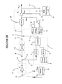
- Each transmitter T i 11 at the transmitter site 13 communicates with a corresponding receiver R i 22 at the receiver site 24 , over a channel characterized by the wavelength of the optical carrier ( ⁇ i ).
- the four signals, each corresponding to a channel ⁇ i , are mixed by a multiplexer 12 prior to insertion on fiber 14 .
- the multi-channel signal is amplified by a post-amplifier 10 and then is transmitted over line amplifiers 20 , 30 , 40 , and 50 , series connected by spans 10' , 20' , 30' , 40' , and 50' , respectively.
- the multichannel signal is first amplified in preamplifier 60 , and separated in individual channel signals in a demultiplexer 21 according to their wavelength ⁇ i .
- the signals for each channel are then applied to a respective receiver R i for decoding.
- a variable optical amplifier VOA 23 is provided at the input of receiver R 1 for controlling the level of the received power (P O ), as needed for the measurements according to the invention.
- the term 'transmission link' or 'link' is used in this specification for designating the amplifiers and fiber spans enclosed in the dotted-line box 100 .
- the term 'transmission path' is used in this specification for designating the equipment and fiber spans between a transmitter T i and a corresponding receiver R i , including the transmitter and the receiver.
- the term 'transmitter-receiver pair' is used to designate a transmitter T i and a receiver R i , which are linked in a particular application over channel ⁇ i , but it does not include the equipment and fiber spans connecting T i to R i .
- 'output point' is used to designate the output of receiver R i such as is point 17 on Figure 1 for channel ⁇ 1 .
- Operating point OP for channel ⁇ 1 is defined by P O and OSNR O values measured at the input of the receiver R 1 , shown at 16 .
- OP is set according to this invention by adjusting the power of the signal P O and adjusting the OSNR O to obtain a value of Q factor in the vicinity of a value of interest, noted here with Q O .
- the BER measured for the current OP 1 of the channel ⁇ 1 comprises information on both noise and distortion of the transmission path.
- the back-to-back BER (BER BB ) measured in OP 1 of channel ⁇ 1 comprises information on the distortion introduced by the T 1 -R 1 pair, and the distortion-free BER (BER DF ) accounts for noise only errors for the entire path.
- the BER M , BER BB values are used for determining the corresponding Q M , Q BB values using formula (2) and the distortion-free Q (Q DF ) is either calculated with formula (2) or determined from the corresponding BER DF value.
- a comparison between Q M and Q BB gives the distortion introduced by the link 100 .
- a comparison between Q BB and Q DF gives the distortion introduced by the transmitter-receiver pair, and a comparison between Q M and Q DF gives the distortion for the entire path.
- the noise loading measurement technique implies intentionally lowering OSNR O to obtain a Q factor of interest (Q O ).
- Q O Q factor of interest
- it is desirable to measure the distortion penalty in the vicinity of Q O 7, for equalization of the channels for example.
- Figure 2A illustrates how the signal at the output of link 100 is noise loaded before arriving at receiver R i .
- Output C of the link 100 is applied to coupler 3 through VOA 2 and mixed with the noise generated by noise source 4 .
- the output of coupler 3 is connected to input D of the receiver 22 .
- the measurement technique according to this invention involves determining a BER value or a corresponding Q parameter using BERV diagrams.
- a BERV diagram is obtained by plotting the values of the BER measured in point 17 as a function of the reference voltage V Ref applied to receiver R 1 on terminal 18 .
- the BER measurements are effected in the known way using a BER measuring unit 33 .
- Output G of the BER measuring unit 33 is connected to point 17 , while V Ref is controlled on input 18 in any suitable way.
- a BER value is then determined graphically on the BERV diagram, and a corresponding Q is calculated using formula (2).
- modified BERV diagrams may be used, where a corresponding Q value is calculated with formula (2) for each BER measurement, and a Q-V diagram is plotted for a satisfactory number of points. Q is determined graphically on the Q-V diagram.
- the Gaussian curve BER f(V Ref ) can be entirely plotted in a reasonable period of time.
- the BER or the equivalent Q determined with formula (2), is determined graphically on an incomplete Q-V diagram, by prolonging the flank of the Gaussian curve. The intersection of these lines gives the BER or Q for the respective operating point (P O , OSNR O ). It is to be noted that the Q-V diagram should contain enough points for allowing an accurate estimation for the BER/Q.
- the noise loading measurement technique involves the following steps. the following steps:
- the information signal is loaded with noise using the distortion measurement unit of Figure 1A connected as shown in Figure 2A.
- Step 2 Once a value of Q close to Q O is obtained, OSNR O of the operating point OP 1 of channel ⁇ 1 is measured for a power P O of the received signal.
- P O and OSNR O are measured in the known manner, using power meter 31 and a spectrometer 32 respectively, as shown in Figure 2A. Namely, output E of power meter 31 and output F of spectrometer 32 are connected to point 16 for the respective measurement.
- Q DF can be calculated in software using a model for receiver R i , and this Q is referred to herein as the 'computed Q DF '. This requires exact knowledge of the receiver parameters such as noise, bandwidth, and receiver thermal noise. Given a model for the receiver, P O and OSNR O entirely determine the performance of the system in the absence of distortion.
- Q DF can also be estimated, using distortion measurement unit (DMU) 1 connected as illustrated in Figure 2B.
- DMU distortion measurement unit
- input 6 of VOA 2 is connected to point A at the output of transmitter unit 11
- channel ⁇ 1 is connected to point D at the input of receiver 22 , replacing link 100 .
- link 100 is replaced with DMU 1 , the distortion introduced by link 100 is eliminated from the measurement, the only units that introduce errors in the measurement are the transmitter and the receiver.
- Wavelength ⁇ 1 is modulated with a test signal comprising a data stream of 'long 1s' and 'long 0s', received from a signal generator 34 , for avoiding data rate distortions.
- output 19 of signal generator 34 is applied to the modulating input 21 of transmitter T 1 , rather than the information signal S IN .
- VOA 23 adjusts the power of the test signal to obtain P O in point 16 .
- Q DF is determined on a Q-V diagram, obtained as explained above. To summarize, a Q value is calculated with formula (2) for each BER measurement, and a Q-V diagram is plotted for a satisfactory number of points. Q DF is then determined graphically on the Q-V diagram.
- Either the computed or the estimated Q DF can be used for determining distortion.
- Step 4 BER BB comprises error information on the noise introduced by the T 1 -R 1 pair.
- This BER BB is measured using again DMU 1 connected as shown in Figure 2B.
- the information signal S IN on terminal 23 is applied on the modulating input 21 of transmitter T i , rather than the test signal from generator 34 .
- the signal on channel ⁇ 1 which is now the signal transported by this channel under normal conditions of operation, is re-routed to the input of VOA 2 so that it travels from transmitter T 1 to receiver R 1 on an alternate distortion-free path. Traffic on all other channels remains unaffected.
- the power of the signal is adjusted using VOAs 2 and 23 to obtain P O on power meter 31 in measuring point 16 , while the noise level is adjusted using VOA 5 to obtain OSNR O on spectrometer 31 in point 16 .
- the value of BER BB is measured on output 17 with BER measuring unit 33 .
- Q BB is then calculated using formula (2), and it contains information introduced by the noise of the T 1 -R 1 pair.
- Step 5 The difference between Q DF and Q BB gives the distortion introduced by the T 1 -R 1 pair, and is denoted by D TR .
- D TR 10 log 10 (Q BB /Q DF )
- Step 6 A Q value (Q M ) is measured in the operating point with the system connected as shown in Figure 2A.
- Q M comprises error information about the noise and distortion introduced into the information signal along the entire path.
- Step 8 The total distortion over T i -R i path is the sum of D TR and D BB and is denoted herein with D P .
- D P D TR + D L
- Figures 3 and 4 are Q-V diagrams illustrating Q's obtained for cases 1 and 2 showing measurements for two different channels ⁇ 1 and ⁇ 2 of the 4- ⁇ OC-192 five-span optical transmission system configuration of Figure 1B.
- the noise floor for these measurements was raised to lower the OSNR, for obtaining the BER values corresponding to a Q value in the vicinity of 7.
- Diagrams (a) and (b) on Figure 3 show Q M
- diagrams (c) and (d) on Figure 4 show Q BB .
- the measurements were effected for the same P O , OSNR O operating point, by varying the receiver reference voltage V Ref .
- a Q M of 6.8 was obtained graphically as shown by the intersection of the dotted lines prolonging the flanks of the BERV diagram (b) on Figure 3.
- Q BB obtained for this measurement was 5.75, shown on Figure 4 as diagram (d).
- Case 3 provides the measurements for channel ⁇ 1 , where the signal at the output of link 100 was noise loaded to an OSNR O of 23.3 dB, which is close to that of case 1.
- Q BB was not measured for this configuration.
- the BER is used as a parameter for evaluating the performance of an optical transmission system. Performance of optical systems is also defined by the Q factor, which uniquely determines the BER in the absence of distortion. The measurements are effected in a point of operation of the channel which gives a value of interest for the Q factor. To this end, the optical SNR is lowered by adding noise over the information signal. A distortion-free Q (Q DF ) and a back-to-back Q (Q BB ) are determined in the same operating point of the system. The distortion penalty for transmitter-receiver pair may be determined by comparing Q DF to Q BB . The noise loading technique will allow to investigate if equalizing. The value of OSNRs at the output of a particular system results in equalizing the noise margin in that systems or not.
Landscapes
- Engineering & Computer Science (AREA)
- Computer Networks & Wireless Communication (AREA)
- Signal Processing (AREA)
- Physics & Mathematics (AREA)
- Electromagnetism (AREA)
- Optical Communication System (AREA)
Applications Claiming Priority (2)
| Application Number | Priority Date | Filing Date | Title |
|---|---|---|---|
| US933875 | 1997-09-19 | ||
| US08/933,875 US6069718A (en) | 1997-09-19 | 1997-09-19 | Distortion penalty measurement procedure in optical systems using noise loading |
Publications (3)
| Publication Number | Publication Date |
|---|---|
| EP0903874A2 true EP0903874A2 (de) | 1999-03-24 |
| EP0903874A3 EP0903874A3 (de) | 2000-08-16 |
| EP0903874B1 EP0903874B1 (de) | 2002-07-31 |
Family
ID=25464642
Family Applications (1)
| Application Number | Title | Priority Date | Filing Date |
|---|---|---|---|
| EP98307423A Expired - Lifetime EP0903874B1 (de) | 1997-09-19 | 1998-09-14 | Distortionsstrafemessverfahren in optischen Systemen mit Geräuschbelastung |
Country Status (4)
| Country | Link |
|---|---|
| US (1) | US6069718A (de) |
| EP (1) | EP0903874B1 (de) |
| CA (1) | CA2246148C (de) |
| DE (1) | DE69806874T2 (de) |
Cited By (5)
| Publication number | Priority date | Publication date | Assignee | Title |
|---|---|---|---|---|
| EP1278313A1 (de) * | 2001-07-19 | 2003-01-22 | Acterna Eningen GmbH | Verfahren und Vorrichtung zur Messung des Q-Faktors eines digitalen Nachrichtenübertragungssystems |
| EP1326362A1 (de) * | 2001-12-21 | 2003-07-09 | Agilent Technologies, Inc. (a Delaware corporation) | Beschleunigte Bitfehlerratenmessung |
| EP1011221A3 (de) * | 1998-12-18 | 2004-10-20 | Fujitsu Limited | Vorrichtung und Verfahren, um Übertragungseigenschaften in einem optischen Wellenlängenmultiplexkommunikationssystem gleichförmig zu machen |
| EP1517459A3 (de) * | 2003-09-18 | 2005-09-07 | ECI Telecom Ltd. | Verfahren und Vorrichtung zur Analyse eines über eine Kommunikationsverbindung gesendeten Signals |
| WO2008037621A1 (de) * | 2006-09-25 | 2008-04-03 | Nokia Siemens Networks Gmbh & Co. Kg | Verfahren zur ermittlung des optischen signal-rausch-verhältnisses und empfangseinrichtung für ein optisches übertragungssystem |
Families Citing this family (23)
| Publication number | Priority date | Publication date | Assignee | Title |
|---|---|---|---|---|
| US6115157A (en) * | 1997-12-24 | 2000-09-05 | Nortel Networks Corporation | Methods for equalizing WDM systems |
| DE19812078A1 (de) * | 1998-03-19 | 1999-09-23 | Siemens Ag | Verfahren zur Überwachung der Signalqualität in transparenten optischen Netzen |
| CA2335289C (en) * | 1998-06-16 | 2009-10-13 | Mohammed Nazrul Islam | Fiber-optic compensation for dispersion, gain tilt, and band pump nonlinearity |
| US6381048B1 (en) * | 1998-09-15 | 2002-04-30 | Lucent Technologies Inc. | Wavelength division multiplexed system having reduced cross-phase modulation |
| US6259543B1 (en) * | 1999-02-17 | 2001-07-10 | Tycom (Us) Inc. | Efficient method for assessing the system performance of an optical transmission system while accounting for penalties arising from nonlinear interactions |
| US6265018B1 (en) * | 1999-08-31 | 2001-07-24 | Lucent Technologies Inc. | Fabricating graded index plastic optical fibers |
| IT1320596B1 (it) * | 2000-08-18 | 2003-12-10 | Marconi Comm Spa | Sistema di trasmissione ottico. |
| US6980737B1 (en) | 2000-10-16 | 2005-12-27 | Nortel Networks Limited | Method and apparatus for rapidly measuring optical transmission characteristics in photonic networks |
| JP3495715B2 (ja) * | 2001-03-01 | 2004-02-09 | 株式会社東芝 | 回線品質監視装置及び回線品質監視方法 |
| WO2003030427A1 (en) * | 2001-10-03 | 2003-04-10 | Tejas Networks India Pvt. Ltd. | Improving osnr of optically amplified dwdm transmission system |
| WO2003030428A1 (en) * | 2001-10-03 | 2003-04-10 | Tejas Networks India Pvt. Ltd. | System for improving osnr of dwdm transmission system |
| US7190902B2 (en) * | 2001-12-12 | 2007-03-13 | Lucent Technologies Inc. | Wavelength exerciser |
| US7206516B2 (en) * | 2002-04-30 | 2007-04-17 | Pivotal Decisions Llc | Apparatus and method for measuring the dispersion of a fiber span |
| JP2006086955A (ja) * | 2004-09-17 | 2006-03-30 | Fujitsu Ltd | 伝送特性評価システムおよびその擬似伝送路装置 |
| GB2399720B (en) * | 2003-03-21 | 2005-10-12 | Agilent Technologies Inc | A method and apparatus for assessing performance of optical systems |
| WO2004095736A1 (ja) * | 2003-04-23 | 2004-11-04 | Fujitsu Limited | 受信誤り率制御装置 |
| US7522846B1 (en) * | 2003-12-23 | 2009-04-21 | Nortel Networks Limited | Transmission power optimization apparatus and method |
| US7899638B2 (en) * | 2005-10-18 | 2011-03-01 | Lecroy Corporation | Estimating bit error rate performance of signals |
| WO2007047613A2 (en) * | 2005-10-18 | 2007-04-26 | Lecroy Corporation | Estimating bit error rate performance of signals |
| US8055128B2 (en) * | 2008-04-07 | 2011-11-08 | Ciena Corporation | Methods and systems for optimal launch power computation in meshed optical networks |
| JP5545752B2 (ja) * | 2010-12-20 | 2014-07-09 | 富士通テレコムネットワークス株式会社 | 光パケット交換システム |
| WO2012119364A1 (en) * | 2011-07-27 | 2012-09-13 | Huawei Technologies Co., Ltd. | Method and apparatus for determining an optical signal-to-noise ratio (OSNR) penalty |
| WO2015157964A1 (zh) * | 2014-04-17 | 2015-10-22 | 华为技术有限公司 | 一种光信噪比的监测方法及装置 |
Family Cites Families (9)
| Publication number | Priority date | Publication date | Assignee | Title |
|---|---|---|---|---|
| JPS63210743A (ja) * | 1987-02-27 | 1988-09-01 | Anritsu Corp | 波長分散測定器 |
| US4823360A (en) * | 1988-02-12 | 1989-04-18 | Northern Telecom Limited | Binary data regenerator with adaptive threshold level |
| US4947459A (en) * | 1988-11-25 | 1990-08-07 | Honeywell, Inc. | Fiber optic link noise measurement and optimization system |
| US5225922A (en) * | 1991-11-21 | 1993-07-06 | At&T Bell Laboratories | Optical transmission system equalizer |
| US5546325A (en) * | 1993-02-04 | 1996-08-13 | International Business Machines Corporation | Automated system, and corresponding method, for testing electro-optic modules |
| WO1995008879A1 (en) * | 1993-09-22 | 1995-03-30 | Massachussetts Institute Of Technology | Error-rate based laser drive control |
| JPH07154378A (ja) * | 1993-12-01 | 1995-06-16 | Kokusai Denshin Denwa Co Ltd <Kdd> | 光伝送特性測定装置 |
| EP0678988B1 (de) * | 1994-04-11 | 1999-02-03 | Hewlett-Packard GmbH | Rauschpegelmessungsverfahren in Gegenwart von einem Signal |
| US5825521A (en) * | 1995-07-24 | 1998-10-20 | Lucent Technologies Inc. | Method of determining inter-symbol interference in transmission systems |
-
1997
- 1997-09-19 US US08/933,875 patent/US6069718A/en not_active Expired - Fee Related
-
1998
- 1998-08-27 CA CA002246148A patent/CA2246148C/en not_active Expired - Lifetime
- 1998-09-14 DE DE69806874T patent/DE69806874T2/de not_active Expired - Fee Related
- 1998-09-14 EP EP98307423A patent/EP0903874B1/de not_active Expired - Lifetime
Cited By (7)
| Publication number | Priority date | Publication date | Assignee | Title |
|---|---|---|---|---|
| EP1011221A3 (de) * | 1998-12-18 | 2004-10-20 | Fujitsu Limited | Vorrichtung und Verfahren, um Übertragungseigenschaften in einem optischen Wellenlängenmultiplexkommunikationssystem gleichförmig zu machen |
| EP1278313A1 (de) * | 2001-07-19 | 2003-01-22 | Acterna Eningen GmbH | Verfahren und Vorrichtung zur Messung des Q-Faktors eines digitalen Nachrichtenübertragungssystems |
| EP1326362A1 (de) * | 2001-12-21 | 2003-07-09 | Agilent Technologies, Inc. (a Delaware corporation) | Beschleunigte Bitfehlerratenmessung |
| EP1517459A3 (de) * | 2003-09-18 | 2005-09-07 | ECI Telecom Ltd. | Verfahren und Vorrichtung zur Analyse eines über eine Kommunikationsverbindung gesendeten Signals |
| US7457354B2 (en) | 2003-09-18 | 2008-11-25 | Eci Telecom Ltd. | Method and device of analyzing a signal transmitted via a communication link |
| WO2008037621A1 (de) * | 2006-09-25 | 2008-04-03 | Nokia Siemens Networks Gmbh & Co. Kg | Verfahren zur ermittlung des optischen signal-rausch-verhältnisses und empfangseinrichtung für ein optisches übertragungssystem |
| US8301025B2 (en) | 2006-09-25 | 2012-10-30 | Nokia Siemens Networks Gmbh & Co. Kg | Method for determining the optical signal-to-noise ratio and receiver device for an optical transmission system |
Also Published As
| Publication number | Publication date |
|---|---|
| EP0903874B1 (de) | 2002-07-31 |
| CA2246148A1 (en) | 1999-03-19 |
| US6069718A (en) | 2000-05-30 |
| EP0903874A3 (de) | 2000-08-16 |
| DE69806874T2 (de) | 2002-11-14 |
| DE69806874D1 (de) | 2002-09-05 |
| CA2246148C (en) | 2002-08-06 |
Similar Documents
| Publication | Publication Date | Title |
|---|---|---|
| EP0903874B1 (de) | Distortionsstrafemessverfahren in optischen Systemen mit Geräuschbelastung | |
| EP0903878B1 (de) | Distortionsstrafemessverfahren in optischen Systemen auf Basis von Signalpegeleinstellung | |
| Sasai et al. | Digital longitudinal monitoring of optical fiber communication link | |
| US6219162B1 (en) | Methods for equalizing WDM systems | |
| US6580531B1 (en) | Method and apparatus for in circuit biasing and testing of a modulated laser and optical receiver in a wavelength division multiplexing optical transceiver board | |
| EP0901617B1 (de) | Messung der verzerrung in optischen übertragungssystemen durch augenmaskenmessung | |
| US6847788B2 (en) | System and method for equalizing transmission characteristics in wavelength division multiplexing optical communication system | |
| US7324758B2 (en) | Optical dispersion monitoring apparatus and optical dispersion monitoring method, and optical transmission system using same | |
| US20020149812A1 (en) | Method and procedures for system test and verification of optical networks using noise injection/loading | |
| US7400830B2 (en) | Quality monitoring method and apparatus for wavelength division multiplexed optical signal and optical transmission system using the same | |
| CN112292819B (zh) | 对应答器噪声性能的自动测量 | |
| US6456409B2 (en) | Method and apparatus for extending fiber transmission distance with multiple pre-emphases in optically amplified DWDM system | |
| US20210203415A1 (en) | Determination of channel osnr and channel osnr margin at real network conditions | |
| Kim et al. | Nonlinear SNR estimation based on power profile estimation in hybrid Raman-EDFA link | |
| US6922532B2 (en) | Optical performance monitoring for D/WDM networks | |
| US5825521A (en) | Method of determining inter-symbol interference in transmission systems | |
| US20020054648A1 (en) | Method for equalizing channel quality differences in a WDM system | |
| May et al. | Demonstration of enhanced power losses characterization in optical networks | |
| US5285473A (en) | System to generate switching criteria and equalize adaptively in data spectrum | |
| Ukagwu et al. | The significance of Q-factor and signal to noise ratio (SNR) in submarine transmission | |
| Ye et al. | Improved BER monitoring based on amplitude histogram and multi-Gaussian curve fitting | |
| Searcy et al. | Experimental Validation of GOSNR Estimation Using Polarization-Resolved Optical Spectrum Analysis on Metro and Long-Haul WDM Links | |
| Chang et al. | In-Band Power Ripple Detection and Localization Using Longitudinal Power Monitoring | |
| CA2261509C (en) | Methods for equalizing wdm systems | |
| Kaeval et al. | Employing Channel Probing to Derive End-of-Life Service Margins for Optical Spectrum Services. To appear in OPTICA Journal of Optical Communications and Networking |
Legal Events
| Date | Code | Title | Description |
|---|---|---|---|
| PUAI | Public reference made under article 153(3) epc to a published international application that has entered the european phase |
Free format text: ORIGINAL CODE: 0009012 |
|
| AK | Designated contracting states |
Kind code of ref document: A2 Designated state(s): DE FR GB |
|
| AX | Request for extension of the european patent |
Free format text: AL;LT;LV;MK;RO;SI |
|
| RAP3 | Party data changed (applicant data changed or rights of an application transferred) |
Owner name: NORTEL NETWORKS CORPORATION |
|
| PUAL | Search report despatched |
Free format text: ORIGINAL CODE: 0009013 |
|
| AK | Designated contracting states |
Kind code of ref document: A3 Designated state(s): AT BE CH CY DE DK ES FI FR GB GR IE IT LI LU MC NL PT SE |
|
| AX | Request for extension of the european patent |
Free format text: AL;LT;LV;MK;RO;SI |
|
| RAP1 | Party data changed (applicant data changed or rights of an application transferred) |
Owner name: NORTEL NETWORKS LIMITED |
|
| 17P | Request for examination filed |
Effective date: 20010216 |
|
| AKX | Designation fees paid |
Free format text: DE FR GB |
|
| GRAG | Despatch of communication of intention to grant |
Free format text: ORIGINAL CODE: EPIDOS AGRA |
|
| RIC1 | Information provided on ipc code assigned before grant |
Free format text: 7H 04B 10/08 A |
|
| RTI1 | Title (correction) |
Free format text: DISTORTION PENALTY MEASUREMENT PROCEDURE IN OPTICAL SYSTEMS USING NOISE LOADING |
|
| RIC1 | Information provided on ipc code assigned before grant |
Free format text: 7H 04B 10/08 A |
|
| RTI1 | Title (correction) |
Free format text: DISTORTION PENALTY MEASUREMENT PROCEDURE IN OPTICAL SYSTEMS USING NOISE LOADING |
|
| 17Q | First examination report despatched |
Effective date: 20010817 |
|
| GRAG | Despatch of communication of intention to grant |
Free format text: ORIGINAL CODE: EPIDOS AGRA |
|
| GRAH | Despatch of communication of intention to grant a patent |
Free format text: ORIGINAL CODE: EPIDOS IGRA |
|
| GRAH | Despatch of communication of intention to grant a patent |
Free format text: ORIGINAL CODE: EPIDOS IGRA |
|
| GRAA | (expected) grant |
Free format text: ORIGINAL CODE: 0009210 |
|
| AK | Designated contracting states |
Kind code of ref document: B1 Designated state(s): DE FR GB |
|
| REG | Reference to a national code |
Ref country code: GB Ref legal event code: FG4D |
|
| RIN1 | Information on inventor provided before grant (corrected) |
Inventor name: KHALEGHI, FARIDEH |
|
| REF | Corresponds to: |
Ref document number: 69806874 Country of ref document: DE Date of ref document: 20020905 |
|
| ET | Fr: translation filed | ||
| PLBE | No opposition filed within time limit |
Free format text: ORIGINAL CODE: 0009261 |
|
| STAA | Information on the status of an ep patent application or granted ep patent |
Free format text: STATUS: NO OPPOSITION FILED WITHIN TIME LIMIT |
|
| 26N | No opposition filed |
Effective date: 20030506 |
|
| PGFP | Annual fee paid to national office [announced via postgrant information from national office to epo] |
Ref country code: GB Payment date: 20070822 Year of fee payment: 10 |
|
| PGFP | Annual fee paid to national office [announced via postgrant information from national office to epo] |
Ref country code: DE Payment date: 20070928 Year of fee payment: 10 |
|
| PGFP | Annual fee paid to national office [announced via postgrant information from national office to epo] |
Ref country code: FR Payment date: 20070904 Year of fee payment: 10 |
|
| GBPC | Gb: european patent ceased through non-payment of renewal fee |
Effective date: 20080914 |
|
| REG | Reference to a national code |
Ref country code: FR Ref legal event code: ST Effective date: 20090529 |
|
| PG25 | Lapsed in a contracting state [announced via postgrant information from national office to epo] |
Ref country code: DE Free format text: LAPSE BECAUSE OF NON-PAYMENT OF DUE FEES Effective date: 20090401 |
|
| PG25 | Lapsed in a contracting state [announced via postgrant information from national office to epo] |
Ref country code: FR Free format text: LAPSE BECAUSE OF NON-PAYMENT OF DUE FEES Effective date: 20080930 |
|
| PG25 | Lapsed in a contracting state [announced via postgrant information from national office to epo] |
Ref country code: GB Free format text: LAPSE BECAUSE OF NON-PAYMENT OF DUE FEES Effective date: 20080914 |
|
| REG | Reference to a national code |
Ref country code: GB Ref legal event code: 732E Free format text: REGISTERED BETWEEN 20101230 AND 20110105 |
|
| REG | Reference to a national code |
Ref country code: DE Ref legal event code: R082 Ref document number: 69806874 Country of ref document: DE Representative=s name: G. KOCH UND KOLLEGEN, DE |
|
| REG | Reference to a national code |
Ref country code: DE Ref legal event code: R082 Ref document number: 69806874 Country of ref document: DE Representative=s name: G. KOCH UND KOLLEGEN, DE Effective date: 20120213 Ref country code: DE Ref legal event code: R081 Ref document number: 69806874 Country of ref document: DE Owner name: CIENA LUXEMBOURG S.A.R.L., LU Free format text: FORMER OWNER: NORTEL NETWORKS LTD., ST. LAURENT, CA Effective date: 20120213 |