EP0903871A2 - Spreizspektrumsignalerzeugungseinrichtung und -verfahren - Google Patents
Spreizspektrumsignalerzeugungseinrichtung und -verfahren Download PDFInfo
- Publication number
- EP0903871A2 EP0903871A2 EP98306565A EP98306565A EP0903871A2 EP 0903871 A2 EP0903871 A2 EP 0903871A2 EP 98306565 A EP98306565 A EP 98306565A EP 98306565 A EP98306565 A EP 98306565A EP 0903871 A2 EP0903871 A2 EP 0903871A2
- Authority
- EP
- European Patent Office
- Prior art keywords
- channel
- signal
- orthogonal
- bit rate
- output
- Prior art date
- Legal status (The legal status is an assumption and is not a legal conclusion. Google has not performed a legal analysis and makes no representation as to the accuracy of the status listed.)
- Granted
Links
Images


Classifications
-
- H—ELECTRICITY
- H04—ELECTRIC COMMUNICATION TECHNIQUE
- H04J—MULTIPLEX COMMUNICATION
- H04J13/00—Code division multiplex systems
- H04J13/10—Code generation
- H04J13/102—Combining codes
-
- H—ELECTRICITY
- H04—ELECTRIC COMMUNICATION TECHNIQUE
- H04B—TRANSMISSION
- H04B1/00—Details of transmission systems, not covered by a single one of groups H04B3/00 - H04B13/00; Details of transmission systems not characterised by the medium used for transmission
- H04B1/69—Spread spectrum techniques
- H04B1/707—Spread spectrum techniques using direct sequence modulation
-
- H—ELECTRICITY
- H04—ELECTRIC COMMUNICATION TECHNIQUE
- H04J—MULTIPLEX COMMUNICATION
- H04J13/00—Code division multiplex systems
- H04J13/0007—Code type
- H04J13/0022—PN, e.g. Kronecker
-
- H—ELECTRICITY
- H04—ELECTRIC COMMUNICATION TECHNIQUE
- H04B—TRANSMISSION
- H04B2201/00—Indexing scheme relating to details of transmission systems not covered by a single group of H04B3/00 - H04B13/00
- H04B2201/69—Orthogonal indexing scheme relating to spread spectrum techniques in general
- H04B2201/707—Orthogonal indexing scheme relating to spread spectrum techniques in general relating to direct sequence modulation
- H04B2201/70706—Orthogonal indexing scheme relating to spread spectrum techniques in general relating to direct sequence modulation with means for reducing the peak-to-average power ratio
Definitions
- the present invention relates to a spread spectrum signal generating device and method and more particularly to a transmitter and a transmission method in a spread spectrum mobile communications system, and in particular, to a spread spectrum signal generating device and method for managing transmit output levels.
- Coherent demodulation is known to be very effective in increasing the subscriber accommodating capacity of a DSS-CDMA mobile communications system due to a small signal-to-noise ratio required to obtain a given frame error rate, as compared to incoherent demodulation.
- the complex gain of a received multipath channel signal of each path should be determined.
- Complex gains are calculated by a decision directed method or a pilot assisted method. The latter is generally used due to its excellent performance and easy realisation.
- pilot assisted method see "Performance of Adaptive Match Filter Receivers Over Fading Multipath Channels" by Pahlavan and Matthews, IEEE Transactions on Communications, Vol. 38, No. 12, December 1990, pp. 2106-221.
- the pilot assisted method is implemented by parallel probing or serial probing.
- parallel probing a transmitter spreads a spread user data signal, including information and data known to a receiver, with different PN (Pseudo random Noise) sequences.
- PN Pulseudo random Noise
- data known to the receiver is periodically inserted into the spread user data signal, including information, and then they are spread with the same PN symbol, in serial probing.
- a user For CDMA mobile radio communications, a user needs to transmit different data such as voice data, control data, and packet data for a high-speed data service or a multimedia service.
- Two cases should be considered for such data transmission: one is that a small peak-to-average power (PAR) ratio at an output terminal of a terminal leads to a decrease in power dissipation and manufacture cost of the terminal; and the other is that intermittent output of the terminal may cause a device that a user carries to malfunction, such as a hearing aid or a cardiometer.
- the serial probing is inferior to the parallel probing in terms of intermitted output, but advantageous over the parallel probing in terms of PAR.
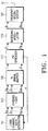
- Figure 1 is a block diagram of a transmitter for generating a transmission signal including a pilot signal on a reverse link in a point-to-point spread spectrum CDMA cellular communications system.
- a logical channel data generator 111 has a plurality of data generators for generating channel data and a plurality of scramblers for scrambling the channel data.
- a channeliser 113 processes the data received from the logical channel data generator 111 in such a manner that interference between channels is small and that the PAR is small.
- An IQ signal mapper 115 maps the channelised signals received from the channeliser 113 into in-phase and quadrature-phase signals.
- a PN spreader 117 spreads the output of the IQ signal mapper 115 with PN codes.
- a baseband modulator 119 translates the spread signal received from the PN spreader 117 to a baseband signal and modulates the baseband signal.
- a frequency upconverter 121 upconverts the frequency of the modulated signal received from the baseband modulator 119 to a transmission frequency and outputs a radio transmission signal.
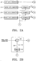
- Figure 2A is a block diagram of the logical channel data generator 111 shown in figure 1 and figure 2B is a block diagram of the scramblers shown in figure 2A.
- the logical channel data generator 111 includes a pilot data generator 211, a control data generator 213, a voice data generator 215, and a packet data generator 217.
- the pilot data generator 211 outputs unmodulated consecutive 0 bits.
- Control data generated from the control data generator 213 is composed of a power control command for power control on a forward link or other control information.
- the voice data generator 215 outputs data from a variable bit rate (VBR) vocoder.
- VBR variable bit rate
- the voice data output from the vocoder can be, for example, a convolutionally encoded and interleaved bit sequence.
- the encoded voice data is output at a VBR of 1 ⁇ 2, 1 ⁇ 4, or 1/8, increasing one bit time by two, four, or eight times.
- the packet data generator 217 has an output bit rate which is an integer multiple of the highest bit rate 1 to 8 of the voice data generator 215.
- Scramblers 219, 221 and 223 scramble the data received from the control data generator 213, the voice data generator 215, and the packet data generator 217, respectively.
- a switch 232 of the scramblers 219, 221 or 223 selectively outputs the output of a decimator 233 or data "0", and an exclusive OR gate 231 exclusive-Ors the data received from the data generators 213, 215, or 217 with the output of the decimator 233 or the data "0" selected by the switch 232.
- the decimator 233 decimates a second PN code sequence (i.e., long PN code sequence) P at the same bit rate as that of the control, voice and packet data, which were all encoded and interleaved.
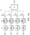
- Figures 3A and 3B are block diagrams of the channeliser 113 shown in figure 1, differently configured according to the serial and parallel probe methods.
- rate adaptors 311 to 317 connected to the respective data generators 211 to 217, adjust the data rates of the data generators 211 to 217.
- Signal mappers 321 to 327 connected to the respective rate adaptors 311 to 317, convert bits 0s and 1s of rate-adapted data to +1s and -1s, respectively.
- Multipliers 331 to 337 multiply converted signals received from the signal mappers 321 to 327 by corresponding channel amplitude control signals A0 to A3.
- a multiplexer 341 multiplexes the outputs of the multipliers 331 to 337.
- each data is time multiplexed to an output C o , to occupy a different time slot and the time that the data occupies is adjusted by varying the number of repetitions of the outputs of the data generators 211 to 217 in the rate-adaptors 311 to 317.
- the rate-adapted data is converted from logical channel data 0s and 1s to +1s and -1s suitable for transmission by the signal converters 321 to 327 and multiplied by the channel amplitude control signals A0 to A3 by the multipliers 331 to 337, thereby determining power levels.
- rate adaptors 351 to 357 are connected to the data generators 211 to 217 of the logical channel data generator 111 and adjust data transmission rates of the corresponding data generators 211 to 217.
- Signal mappers 361 to 367 are connected to the corresponding rate adaptors 351 to 357, for converting bits 0s and 1s of rate-adapted data to +1s and -1s, respectively.
- Walsh c code generators 371 to 377 generate Walsh codes WO to W3.
- Multipliers 381 to 387 multiply signals received from the signal mappers 321 to 327 by the Walsh codes W0 to W3 received from the Walsh code generators 371 to 377 to reduce or remove interference between channels and phase errors.
- the Walsh code generators 371 to 377 and the multipliers 381 to 387 serve as an interference remover.
- Multipliers 391 to 397 multiply the outputs of the multipliers 381 to 387 by the corresponding channel amplitude control signals A0 to A3 acting as a channel amplitude controller.
- the occupation time of each data is adjusted by varying the number of repetitions of the outputs of the data generators 211 to 217 by the rate adaptors 351 to 357.
- the rate-adapted data is converted from logical channel data 0s and 1s to +1s and -1s suitable for transmission by the signal mappers 321 to 217, and multiplied by the mutually orthogonal Walsh codes by the multipliers 381 to 387 thereby reducing interference between channels and phase error-induced performance deterioration.
- the outputs of the multipliers 381 to 387 are multiplied by the corresponding channel amplitude control signals A0 to A3 by multipliers 391 to 397 so that power levels are controlled.
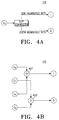
- Figure 4A is a block diagram of the IQ signal mapper 115 shown in figure 1, which is connected to the channeliser 113 for the serial probe scheme
- figure 4B is a block diagram of the IQ signal mapper 115 shown in figure 1, which is connected to the channeliser 113 for the parallel probe scheme.
- the IQ signal mapper 115 maps a channelised signal into in-phase and quadrature-phase signals.
- the IQ signal mapper 115 of figure 4 is provided with a serial-to-parallel converter 411 for separating the multiplexed signal into odd-numbered bits and even-numbered bits and generating an in-phase signal (I signal) and a quadrature-phase signal (Q signal).
- I signal in-phase signal
- Q signal quadrature-phase signal
- the IQ signal mapper 115 of figure 4B has an adder 421 for adding the pilot channel signal C o and the voice channel signal C 2 and thus generating an I signal, and an adder 423 for adding the control channel signal C 1 and the packet channel signal C 1 and thus generating a Q signal.
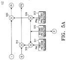
- Figure 5A is a block diagram of the PN spreader 117 shown in figure 1 using an IQ split method
- figure 5B is a block diagram of a PN spreader 117 shown in figure 1 using a complex spreading method.
- a first PN code refers to a short PN code
- a second PN code refers to a long PN code, see for example, IS-IT 5 standard reverse link spreading.
- a first Pni code generator 511 generates an in-phase PN code, Pni, and a first PNq code generator 513 generates a quadrature-phase PN code, PNq.
- a second PN code generator 515 generates a long PN code commonly applied to the in-phase PN code, Pni and the quadrature-phase PN code, PNq.
- a multiplier 571 multiplies PNi by the second PN code thereby generating an in-phase PN code.
- a multiplier 519 multiplies PNq by the second PN code, thereby generating a quadrature-phase PN code.
- a multiplier 520 multiplies the I signal received from the IQ signal mapper 115 by the quadrature-phase PN code and generates a spread signal PI.
- a multiplier 512 multiplies the Q signal received from the IQ signal mapper 115 by the in-phase PN code and generates a spread signal PQ.
- the first PNi code generator 511 generates the in-phase PN code, PNi, and the first PNq code generator 513 generates a quadrature-phase PN code PNq.
- the second PN code generator 515 generates a long PN code commonly applied to both of the PN codes PNi and PNq.
- the multiplier 517 multiplies PNi by the second PN code thereby generating an in-phase PN code.
- the multiplier 519 multiplies PNq by the second PN code thereby generating a quadrature-phase PN code.
- a multiplier 521 multiplies the I signal received from the IQ signal mapper 115 by the in-phase PN code.
- a multiplier 523 multiplies the Q signal received from the IQ signal mapper 115 by the in-phase PN code.
- a multiplier 525 multiplies the Q signal received from the IQ signal mapper 115 by the quadrature-phase PN code.
- a multiplier 527 multiplies the I signal received from the IQ signal mapper 115 by the quadrature-phase PN code.
- a subtracter 529 subtracts the output of the multiplier 525 from the output of the multiplier 521 and generates a complex-spread in-phase signal PI.
- An adder 531 adds the outputs of the multipliers 523 and 527 and generates a complex-spread quadrature-phase signal PQ.
- the PN spreader 117 of figure 5B is advantageous over that figure 5A in terms of peak-to-average power ratio.
- the baseband modulator 119 configured as shown in figure 6 modulates the spread signals PI and PQ received from the PN spreader 117 shown in figure 5A or 5B.
- the spread signal PI is filtered by an FIR (Finite Impulse Response) filter 615 whereas the spread signal PQ is delayed by a predetermined time in a delay 611 and filtered by an FIR filter 613.
- the baseband modulator 119 may operate based on OQAM (offset Quadrature Amplitude Modulation).
- a transmitter using the parallel probe method includes the channeliser 113 of figure 3B, the IQ signal mapper 115 of figure 4B, the PN spreader 117 of figure 5B and the baseband modulator 119 of figure 6.
- a transmitter using the serial probe method has the channeliser 113 of figure 3A, the IQ signal mapper 115 of figure 4A, the PN spreader 117 of figure 5A, and the baseband modulator 119 of figure 6.
- the transmitter using the parallel probe method increases PAR, and that of the serial probe method suffers a significant power variation due to a varied bit rate of a voice signal and the intermittent presence of a packet signal, thereby increasing interference.
- a peak-to-average power ratio is increased, which implies that the amplifier should exhibit an excellent linearity.
- a terminal using only the voice channel (i.e. low speed traffic channel) without the packet channel (i.e. high speed traffic channel) may have a significantly increased peak-to-average power ratio depending on gain adjustment for channels.
- a first of the present invention provides a spread spectrum signal generating device for a transmitter of a mobile communication system using a plurality of channels comprising at least one of either constant bit rate and constant power level signals and at least one of either variable bit rate and variable power level signals, the device comprising: means for producing and outputting a time multiplexed channel by time multiplexing only the constant bit rate and constant power level signals for output on a first channel; and means for outputting at least one of the variable bit rate and variable power level signals on a second channel which is independent of the first channel.
- a device further comprising encoders for orthogonally spreading the first channel and the second channel using respective orthogonal codes.
- An embodiment provides a device wherein the plurality of channels comprises a pilot channel signal, a control channel signal, a voice channel signal and a packet channel signal, and wherein means for producing a time multiplexed channel comprises: a multiplexer for time multiplexng the pilot channel signal and the control channel signal; a first orthogonal encoder for orthogonally spreading the output of the multiplexer using an orthogonal code; a second orthogonal encoder for orthogonally spreading the voice channel signal having a variable bit rate using an orthogonal code; a third orthogonal encoder for orthogonally spreading the packet channel signal having a variable bit rate using an orthogonal code; an IQ signal mapper for adding the outputs of the first and third orthogonal encoders, outputting the added signal on the first channel and outputting the output of the second orthogonal encoder on the second channel.
- the IQ mapper further comprises means for outputting the output of the second orthogonal encoder on the second channel in the presence of a voice channel signal; and means for outputting the outputs of the first and third orthogonal encoders on the first channel and the second channel respectively in the absence of a voice channel signal.
- en embodiment provides a device further comprising a PN spreader for spreading the first and second channels using PN codes to produce a spread spectrum signal; and means for outputting the spread spectrum signal.
- the PN spreader comprises means for complex-multiplying the first and second channels using PN codes.
- a preferred embodiment provides a device further comprising a baseband modulator for baseband filtering the output of the PN spreader and modulating the filtered signal.; and/or a frequency converter for upconverting the frequency of the output of the baseband modulator to a transmission frequency.
- a preferred embodiment provides a device wherein the means for producing and outputting a time multiplexed channel comprises a plurality of rate adaptors for adjusting the rates of the at least one of either constant bit rate and constant power level signals and at least one of either variable bit rate and variable power level signals; a plurality of signal mappers for converting the Os and 1s received from the rate adaptors into +1s and -1s respectively; a plurality of channel amplitude controllers for multiplying the outputs of the signal mappers by corresponding channel amplitude control values.
- an embodiment provides a device wherein the orthogonal codes comprises multipath resistant pseudo codes (MRPOCs) such as are described in the appendix.
- MRPOCs multipath resistant pseudo codes
- a second aspect of the present invention provides a spread spectrum signal generating method for a transmitter of a mobile communication system using a plurality of channels comprising at least one of either constant bit rate and constant power level signals and at least one of either variable bit rate and variable power level signals, the method comprising the steps of producing and outputting a time multiplexed channel by time multiplexing only the constant bit rate and constant power level signals for output on a first channel; and outputting at least one of the variable bit rate and variable power level signals on a second channel which is independent of the first channel.
- a preferred embodiment provides a method further comprising the step of orthogonally spreading the first channel and the second channel using respective orthogonal codes.
- a method wherein the plurality of channels comprises a pilot channel signal, a control channel signal, a voice channel signal and a packet channel signal, and wherein the step of producing a time multiplexed channel comprises the steps of time multiplexng the pilot channel signal and the control channel signal; orthogonally spreading, using a first orthogonal encoder, the output of the multiplexer using an orthogonal code; orthogonally spreading, using a second orthogonal encoder, the voice channel signal having a variable bit rate using an orthogonal code; orthogonally spreading, using a third orthogonal encoder, the packet channel signal having a variable bit rate using an orthogonal code; and adding the outputs of the first and third orthogonal encoders, outputting the added signal on the first channel and outputting the output of the second orthogonal encoder on the second channel.
- An embodiment preferably provides a method further comprising the steps of outputting the output of the second orthogonal encoder on the second channel in the presence of a voice channel signal; and outputting the outputs of the first and third orthogonal encoders on the first channel and the second channel respectively in the absence of a voice channel signal.
- a method further comprising the steps of spreading, using a PN spreader, the first and second channels using PN codes to produce a spread spectrum signal; and outputting the spread spectrum signal.
- An embodiment of the present invention provides a method wherein the step of spreading comprises the step complex-multiplying the first and second channels using PN codes.
- a method provides a method further comprising the steps of baseband filtering, using a baseband modulator, the output of the PN spreader; and modulating the filtered signal.
- a preferred embodiment provides a method further comprising the step of upconverting, using a frequency converter, the frequency of the output of the baseband modulator to a transmission frequency.
- the step of producing and outputting a time multiplexed channel comprises the steps of adjusting, using a plurality of rate adaptors, the rates of the at least one of either constant bit rate and constant power level signals and at least one of either variable bit rate and variable power level signals; converting, using a plurality of signal mappers, the 0s and 1s received from the rate adaptors into +1s and -1s respectively; multiplying, using a plurality of channel amplitude controller, the outputs of the signal mappers by corresponding channel amplitude control values.
- an embodiment provides a method wherein the orthogonal codes comprises multipath resistant pseudo codes (MRPOCs).
- MRPOCs multipath resistant pseudo codes
- Embodiments of the present invention advantageously provide a spread spectrum signal generating device and method in a mobile communications system for transmitting data of multiple logical channels, where the data of logical channels having constant transmit power levels is channelised by multiplexing and orthogonal codes.
- Embodiments facilitate the provision a spread spectrum signal generating device in a mobile communications system for transmitting data of multiple logical channels, where the data of logical channels having a constant transmit power levels is channelised by multiplexing and the data of the other logical channels is channelised on the basis of the power level of the multiplexed channel.
- An embodiment provides a spread spectrum signal generating device in a transmitter of a mobile communications system using a plurality of logical channels.
- a multiplexer time multiplexes a pilot channel signal and a control channel signal which are output at constant power levels, a first orthogonal encoder orthogonally spreads the output of the multiplexer with an orthogonal code, a second orthogonal encoder orthogonally spreads voice channel data of a variable bit rate with an orthogonal code, a third orthogonal encoder orthogonally spreads packet channel data of a variable bit rate with an orthogonal code, an IQ signal mapper adds the outputs of the first and third orthogonal encoders, outputs the added signal as a first channel signal, and outputs the output of the second orthogonal encoder as a second channel signal, and a PN spreader spreads the first and second channel signals with PN codes and outputs a final spectrum spread signal. Therefore, a peak-to-average power ratio of the transmitter is maintained at
- Simultaneous transmission of pilot data, control data, voice data, and packet data increases a peak-to-average power ratio in a mobile communications system for transmitting data of multiple logical channels. This may cause problems in the linearity of a power amplifier of a transmitter.
- the peak-to-average power ratio and the number of orthogonal codes used for channelisation can be reduced by channelising a pilot signal and a data signal through time multiplexing.
- the power ratio of pilot channel: control channel: voice channel is 1:1/4:4 and a peak-to-average power ratio at an output terminal is 6.95dB.
- voice data having a bit rate of one eighth of the highest bit rate the power ratio becomes 1:1/4:1/2 and the peak-to-average power ratio is 7.23dB.
- the average energy ratio per unit time of the pilot channel to the control channel is fixed at 1:1/4.
- the voice channel since the voice channel has a variable bit rate, it has 4-1/2 times the average energy of the pilot channel.
- the peak-to-average power ratio increases as the difference in energy between channels which are added in the IQ signal mapper 115 reduces.
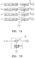
- the logical channel data generator 111 is configured as shown in figures 7A and 7B, and the channeliser 113 is constituted as shown in figure 8 so that the power level of the multiplexed pilot/control channel is et to be the sum of the power level of the pilot channel and the power level of the control channel in parallel probing. For example, if the power level of the pilot channel is 1 and that of the control channel is 1 ⁇ 4 in parallel probing then the power level of the time multiplexed pilot/control channel is 1+1 ⁇ 4.
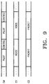
- the control channel is output for 4/5 time as shown in figure 9.
- Figure 7A is a block diagram of the logical channel data generator 111 according to an embodiment of the present invention
- figure 7B is a block diagram of scramblers shown in figure 7A.
- the logical channel data generator 111 includes a pilot data generator 711, a control data generator 713, a voice data generator 715, and a packet data generator 717.
- the pilot data generator 711 outputs unmodulated consecutive bits 0s.
- Control data generated from the control data generator 713 comprises a power control command for power control on a forward link or other control information.
- the voice data generator 715 outputs data from a vocoder at a variable bit rate.
- the voice data output from the vocoder can be, for example, a convolutionally encoded and interleaved bit sequence.
- the encoded voice data is output at a VBR of 1/2, 1/4, or 1/8, increasing one bit time by two, four, or eight times.
- the packet data generator 717 has an output bit rate which is an integer multiple of the highest bit rate 1 to 8 of the voice data generator 215. Scramblers 721 to 727 scramble the data received from the data generators 711 to 717.
- a decimator 733 of the scrambler 721 to 727 decimates according to a predetermined value P, and an exclusive OR gate 731 exclusive Ors the output of the data generators 711 to 717 with the output of the decimator 733.
- the pilot data, control data, voice data, and packet data are all encoded and interleaved.
- the interleaved data is exclusive ORed with the data resulting from decimating a second PN code sequence at the same bit rate as that of the interleaved data.
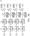
- Figure 8 is a block diagram of the channeliser 113 according to the embodiment of the present invention.
- rate adaptors 811 to 817 are connected to the corresponding data generators 711 to 717, for adjusting the data transmission rates of the data generators 711 to 717.
- Signal mappers 821 to 827 are connected to the rate adaptors 811 to 817, for converting bits, 0s and 1s, of the rate-adapted data to + 1s and - 1s, respectively.
- Multipliers 831 to 837 multiply the outputs of the signal mappers 821 to 827 by the corresponding channel amplitude control signals A0 to A3.
- a multiplexer 841 multiplexes the outputs of the multipliers 831 and 832.
- the multiplexed signal is a pilot/control channel signal.
- a pseudo-orthogonal encoder 842 spreads the pilot/control channel signal with a multipath resistant pseudo-orthogonal code (MRPOC) to overcome the problem or orthogonality loss caused by a multipath signal component.
- MRPOC multipath resistant pseudo-orthogonal code
- a pseudo-orthogonal encoder 845 spreads the voice data channel signal with an MRPOC
- a pseudo-orthogonal encoder 847 spreads the packet data channel signal with an MRPOC.
- MRPOCs are described in the appendix and are the subject of co-pending application reference P71033EP.
- the gains A 0 and A 1 in this invention have identical values computed from E and F by equations (1) and the pilot and control channels are output for the time periods calculated by equations (2) and (3), respectively.
- a 0 E 2 + F 2
- a 1 E 2 + F 2 E 2 E 2 + F 2 F 2 E 2 + F 2
- the multiplexer 841 of figure 8 multiplexes the pilot and control channel signals to a signal C 0 as shown in figure 9, and the voice and packet data channel signals are output without being multiplexed.
- the output of the multiplexer 841, the voice data signal, and the packet data signal are spread by the pseudo-orthogonal encoders 843 to 847 thereby ensuring orthogonality which would otherwise be lost due to a multipath propagated component.
- the voice channel signal When the voice channel transmits power, that is, in the presence of voice data, the voice channel signal is output as a Q channel signal, as shown in figure 10A, and the packet/control channel signal is added to the packet data signal by an adder and output as an I channel signal. In the absence of voice data, the packet signal is output as a Q channel signal and the packet/control signal is output as an I channel signal, as shown in figure 10B.
- the IQ signal mapper 115 When power is transmitted from the voice channel output from the channeliser 113, the IQ signal mapper 115 outputs the voice channel signal in using a phase which is different to that of the pilot/control channel and adds the packet data and the pilot/control channel signal to the other output, as shown in figure 10A. If the voice channel is off, the packet channel signal is output using a phase which is different to that if the pilot/control channel signal, as shown in figure 10B.
- the PN spreader 117 in the embodiment of the present invention may be configured as shown in figure 5B and reduces a peak-to-average power ratio.
- the modulation follows the method of figure 6
- the peak-to-average power ratio is smaller than that in a general parallel probe method by between 1.5-1.9dB.
- the Walsh encoders of figure 3B or inner codes of a pseudo-orthogonal code can be used for the pseudo-orthogonal encoders 843 to 847 of figure 8.
- a PN sequence should be generated to have an appropriate bit rate in a PN code generator. Since pilot data is always uniform, use of the pseudo-orthogonal codes may cause interference to other users. To prevent this, the pilot data is scrambled by a scrambling sequence decimated from the second PN code generator.
- a pilot signal and a data signal are channelised through time multiplexing in a mobile communications system using a plurality of logical channels such as pilot data, control data, voice data and packet data thereby reducing a peak-to-average power ration and the number of orthogonal codes involved in channelisation.
Landscapes
- Engineering & Computer Science (AREA)
- Computer Networks & Wireless Communication (AREA)
- Signal Processing (AREA)
- Mobile Radio Communication Systems (AREA)
- Cable Transmission Systems, Equalization Of Radio And Reduction Of Echo (AREA)
- Radio Relay Systems (AREA)
Applications Claiming Priority (4)
| Application Number | Priority Date | Filing Date | Title |
|---|---|---|---|
| KR1019970039200A KR100369794B1 (ko) | 1997-08-18 | 1997-08-18 | 이동통신시스템의송신장치의대역확산신호발생장치및방법 |
| KR3920097 | 1997-08-18 | ||
| KR3919997 | 1997-08-18 | ||
| KR1019970039199A KR19990016606A (ko) | 1997-08-18 | 1997-08-18 | 씨디엠에이 이동통신시스템의 의사직교부호를 이용한 대역확산신호 발생장치 및 방법 |
Publications (3)
| Publication Number | Publication Date |
|---|---|
| EP0903871A2 true EP0903871A2 (de) | 1999-03-24 |
| EP0903871A3 EP0903871A3 (de) | 1999-04-21 |
| EP0903871B1 EP0903871B1 (de) | 2004-06-30 |
Family
ID=26633009
Family Applications (1)
| Application Number | Title | Priority Date | Filing Date |
|---|---|---|---|
| EP98306565A Expired - Lifetime EP0903871B1 (de) | 1997-08-18 | 1998-08-18 | Spreizspektrumsignalerzeugungseinrichtung und -verfahren |
Country Status (2)
| Country | Link |
|---|---|
| EP (1) | EP0903871B1 (de) |
| DE (1) | DE69824802T2 (de) |
Cited By (8)
| Publication number | Priority date | Publication date | Assignee | Title |
|---|---|---|---|---|
| WO1999001994A3 (en) * | 1997-07-01 | 1999-06-17 | Qualcomm Inc | A subscriber unit and method for use in a wireless communication system |
| WO2001043301A1 (de) * | 1999-12-06 | 2001-06-14 | Fraunhofer-Gesellschaft zur Förderung der angewandten Forschung e.V. | Par- und ausserbandstrahlungs- reduzierung in codemultiplex-modulationssystemen |
| US6304563B1 (en) | 1999-04-23 | 2001-10-16 | Qualcomm Incorporated | Method and apparatus for processing a punctured pilot channel |
| FR2916116A1 (fr) * | 2007-05-11 | 2008-11-14 | France Telecom | Procedes d'emission et de reception d'un signal a porteuses multiples et a etalement de spectre,signal,produits programme d'ordinateur,et dispositifs d'emission et de reception correspondants. |
| US7929723B2 (en) | 1997-01-13 | 2011-04-19 | Micro Ear Technology, Inc. | Portable system for programming hearing aids |
| US8213485B2 (en) | 1996-05-28 | 2012-07-03 | Qualcomm Incorporated | High rate CDMA wireless communication system using variable sized channel codes |
| US8300862B2 (en) | 2006-09-18 | 2012-10-30 | Starkey Kaboratories, Inc | Wireless interface for programming hearing assistance devices |
| US9344817B2 (en) | 2000-01-20 | 2016-05-17 | Starkey Laboratories, Inc. | Hearing aid systems |
Family Cites Families (2)
| Publication number | Priority date | Publication date | Assignee | Title |
|---|---|---|---|---|
| CA2158269A1 (en) * | 1994-02-25 | 1995-08-31 | Michael Dale Kotzin | Method and apparatus for time division multiplexing the use of spreading codes in a communication system |
| US6396804B2 (en) * | 1996-05-28 | 2002-05-28 | Qualcomm Incorporated | High data rate CDMA wireless communication system |
-
1998
- 1998-08-18 DE DE69824802T patent/DE69824802T2/de not_active Expired - Fee Related
- 1998-08-18 EP EP98306565A patent/EP0903871B1/de not_active Expired - Lifetime
Cited By (17)
| Publication number | Priority date | Publication date | Assignee | Title |
|---|---|---|---|---|
| US8588277B2 (en) | 1996-05-28 | 2013-11-19 | Qualcomm Incorporated | High data rate CDMA wireless communication system using variable sized channel codes |
| US6396804B2 (en) | 1996-05-28 | 2002-05-28 | Qualcomm Incorporated | High data rate CDMA wireless communication system |
| US6549525B2 (en) | 1996-05-28 | 2003-04-15 | Qualcomm Incorporated | High data rate CDMA wireless communication system |
| US8213485B2 (en) | 1996-05-28 | 2012-07-03 | Qualcomm Incorporated | High rate CDMA wireless communication system using variable sized channel codes |
| US7929723B2 (en) | 1997-01-13 | 2011-04-19 | Micro Ear Technology, Inc. | Portable system for programming hearing aids |
| WO1999001994A3 (en) * | 1997-07-01 | 1999-06-17 | Qualcomm Inc | A subscriber unit and method for use in a wireless communication system |
| US6304563B1 (en) | 1999-04-23 | 2001-10-16 | Qualcomm Incorporated | Method and apparatus for processing a punctured pilot channel |
| US7471657B2 (en) | 1999-04-23 | 2008-12-30 | Qualcomm, Incorporated | Method and apparatus for processing a punctured pilot channel |
| US7505507B2 (en) | 1999-12-06 | 2009-03-17 | Ericsson Gmbh | Apparatus and method for generating a transmit sequence and apparatus and method for retrieving information |
| US7126980B1 (en) | 1999-12-06 | 2006-10-24 | Fraunhofer-Gesellschaft Zur Foerderung Der Angewandten Forschung E.V. | PAR and out-of-band radiation reduction in code multiplex modulation systems |
| WO2001043301A1 (de) * | 1999-12-06 | 2001-06-14 | Fraunhofer-Gesellschaft zur Förderung der angewandten Forschung e.V. | Par- und ausserbandstrahlungs- reduzierung in codemultiplex-modulationssystemen |
| US9344817B2 (en) | 2000-01-20 | 2016-05-17 | Starkey Laboratories, Inc. | Hearing aid systems |
| US9357317B2 (en) | 2000-01-20 | 2016-05-31 | Starkey Laboratories, Inc. | Hearing aid systems |
| US8300862B2 (en) | 2006-09-18 | 2012-10-30 | Starkey Kaboratories, Inc | Wireless interface for programming hearing assistance devices |
| WO2008145917A3 (fr) * | 2007-05-11 | 2009-03-26 | France Telecom | Procedes d'emission et de reception d'un signal a porteuses multiples et a etalement de spectre, signal, produits programme d'ordinateur, et dispositifs d'emission et de reception correspondants |
| FR2916116A1 (fr) * | 2007-05-11 | 2008-11-14 | France Telecom | Procedes d'emission et de reception d'un signal a porteuses multiples et a etalement de spectre,signal,produits programme d'ordinateur,et dispositifs d'emission et de reception correspondants. |
| US8432951B2 (en) | 2007-05-11 | 2013-04-30 | France Telecom | Methods for transmitting and receiving a multicarrier spread-spectrum signal, corresponding signal, computer program products and transmission and reception devices |
Also Published As
| Publication number | Publication date |
|---|---|
| EP0903871A3 (de) | 1999-04-21 |
| DE69824802T2 (de) | 2005-07-14 |
| EP0903871B1 (de) | 2004-06-30 |
| DE69824802D1 (de) | 2004-08-05 |
Similar Documents
| Publication | Publication Date | Title |
|---|---|---|
| US6396868B1 (en) | Spread spectrum signal generating device and method in transmitter of mobile communications system | |
| EP0944182B1 (de) | Verfahren und Vorrichtung zur Regelung der Sendeleistung in einem CDMA-Endgerät | |
| EP0809364B1 (de) | Spreizspektrumnachrichtenübertragungssystem | |
| RU2313176C2 (ru) | Абонентский блок и способ его использования в беспроводной системе связи | |
| JP4307553B2 (ja) | 高データ速度cdma無線通信システム | |
| RU2358389C2 (ru) | Абонентское устройство и способ его использования в системе беспроводной связи | |
| JP3390771B2 (ja) | 直接シーケンス帯域拡散コードチップ変調装置 | |
| AU734411B2 (en) | Device and method for generating spreading code and spreading channel signals using spreading code in CDMA communication system | |
| US7342904B2 (en) | Method and apparatus for orthogonally overlaying variable chip rate spread spectrum signals | |
| KR19990014914A (ko) | 이중 직교 코드 및 주파수 분할 다중 접속 통신시스템 | |
| US6781980B1 (en) | CDMA transmitter and method generating combined high-rate and low-rate CDMA signals | |
| KR960000353B1 (ko) | 스프레드 스펙트럼 통신 시스템내 가변수의 통신 채널 수용 방법 및 그 장치 | |
| EP0903871B1 (de) | Spreizspektrumsignalerzeugungseinrichtung und -verfahren | |
| WO2001008326A1 (en) | Chip-synchronous cdma multiplexer and method resulting in constant envelope signals | |
| JP2000228659A (ja) | パケット送信装置 | |
| EP0999668A2 (de) | Verfahren und Vorrichtung zur Veränderung der Kanalanzahl in Spreizspektrumkommunikationssystemen | |
| EP1135864B1 (de) | Gerät und verfahren zur erhöhung der kanalanzahl in einem cdma system | |
| KR100259051B1 (ko) | 직접 씨퀀스 씨디엠에이 이동 통신시스템의 오프-셋 사진위상천이변조장치 및 방법 | |
| WO2001022607A2 (en) | Code division multiple access communication | |
| MXPA99010403A (es) | Una unidad suscriptora y metodo para utilizarse en un sistema de comunicacion inalambrico |
Legal Events
| Date | Code | Title | Description |
|---|---|---|---|
| PUAI | Public reference made under article 153(3) epc to a published international application that has entered the european phase |
Free format text: ORIGINAL CODE: 0009012 |
|
| PUAL | Search report despatched |
Free format text: ORIGINAL CODE: 0009013 |
|
| 17P | Request for examination filed |
Effective date: 19980818 |
|
| AK | Designated contracting states |
Kind code of ref document: A2 Designated state(s): DE FR GB |
|
| AX | Request for extension of the european patent |
Free format text: AL;LT;LV;MK;RO;SI |
|
| AK | Designated contracting states |
Kind code of ref document: A3 Designated state(s): AT BE CH CY DE DK ES FI FR GB GR IE IT LI LU MC NL PT SE |
|
| AX | Request for extension of the european patent |
Free format text: AL;LT;LV;MK;RO;SI |
|
| RIN1 | Information on inventor provided before grant (corrected) |
Inventor name: KIM, JE-WOO Inventor name: CHUNG, HA-BONG Inventor name: SONG, HONG-YEOP SAMSUNG ELECTRONICS CO. LIMITED Inventor name: NO, JONG-SEON Inventor name: KIM, YOUNG-KY SAMSUNG ELECTRONICS CO. LIMITED Inventor name: KANG, HEE-WON Inventor name: AHN, JAE-MIN Inventor name: YOON, SOON-YOUNG |
|
| RIN1 | Information on inventor provided before grant (corrected) |
Inventor name: KIM, JE-WOO Inventor name: CHUNG, HA-BONG.SAMSUNG ELECTRONICS CO.LIMITED Inventor name: SONG, HONG-YEOP SAMSUNG ELECTRONICS CO. LIMITED Inventor name: NO, JONG-SEON Inventor name: KIM, YOUNG-KY SAMSUNG ELECTRONICS CO. LIMITED Inventor name: KANG, HEE-WON Inventor name: AHN, JAE-MIN Inventor name: YOON, SOON-YOUNG. SAMSUNG ELECTRONICS CO,LTD. |
|
| AKX | Designation fees paid |
Free format text: DE FR GB |
|
| 17Q | First examination report despatched |
Effective date: 20030228 |
|
| GRAP | Despatch of communication of intention to grant a patent |
Free format text: ORIGINAL CODE: EPIDOSNIGR1 |
|
| RIN1 | Information on inventor provided before grant (corrected) |
Inventor name: KIM, JE-WOO Inventor name: CHUNG, HA-BONGSAMSUNG ELECTRONICS CO., LTD Inventor name: SONG, HONG-YEOPSAMSUNG ELECTRONICS CO., LTD Inventor name: NO, JONG-SEON Inventor name: KIM, YOUNG-KYSAMSUNG ELECTRONICS CO., LTD Inventor name: KANG, HEE-WON Inventor name: AHN, JAE-MIN Inventor name: YOON, SOON-YOUNGSAMSUNG ELECTRONICS CO., LTD |
|
| GRAS | Grant fee paid |
Free format text: ORIGINAL CODE: EPIDOSNIGR3 |
|
| GRAA | (expected) grant |
Free format text: ORIGINAL CODE: 0009210 |
|
| AK | Designated contracting states |
Kind code of ref document: B1 Designated state(s): DE FR GB |
|
| REG | Reference to a national code |
Ref country code: GB Ref legal event code: FG4D |
|
| REF | Corresponds to: |
Ref document number: 69824802 Country of ref document: DE Date of ref document: 20040805 Kind code of ref document: P |
|
| ET | Fr: translation filed | ||
| PLBE | No opposition filed within time limit |
Free format text: ORIGINAL CODE: 0009261 |
|
| STAA | Information on the status of an ep patent application or granted ep patent |
Free format text: STATUS: NO OPPOSITION FILED WITHIN TIME LIMIT |
|
| 26N | No opposition filed |
Effective date: 20050331 |
|
| PGFP | Annual fee paid to national office [announced via postgrant information from national office to epo] |
Ref country code: DE Payment date: 20080829 Year of fee payment: 11 |
|
| PGFP | Annual fee paid to national office [announced via postgrant information from national office to epo] |
Ref country code: FR Payment date: 20080818 Year of fee payment: 11 |
|
| PGFP | Annual fee paid to national office [announced via postgrant information from national office to epo] |
Ref country code: GB Payment date: 20080827 Year of fee payment: 11 |
|
| GBPC | Gb: european patent ceased through non-payment of renewal fee |
Effective date: 20090818 |
|
| REG | Reference to a national code |
Ref country code: FR Ref legal event code: ST Effective date: 20100430 |
|
| PG25 | Lapsed in a contracting state [announced via postgrant information from national office to epo] |
Ref country code: FR Free format text: LAPSE BECAUSE OF NON-PAYMENT OF DUE FEES Effective date: 20090831 Ref country code: DE Free format text: LAPSE BECAUSE OF NON-PAYMENT OF DUE FEES Effective date: 20100302 |
|
| PG25 | Lapsed in a contracting state [announced via postgrant information from national office to epo] |
Ref country code: GB Free format text: LAPSE BECAUSE OF NON-PAYMENT OF DUE FEES Effective date: 20090818 |