EP0903833A1 - Electrical machine with squirrel cage rotor - Google Patents
Electrical machine with squirrel cage rotor Download PDFInfo
- Publication number
- EP0903833A1 EP0903833A1 EP98116861A EP98116861A EP0903833A1 EP 0903833 A1 EP0903833 A1 EP 0903833A1 EP 98116861 A EP98116861 A EP 98116861A EP 98116861 A EP98116861 A EP 98116861A EP 0903833 A1 EP0903833 A1 EP 0903833A1
- Authority
- EP
- European Patent Office
- Prior art keywords
- rotor
- stator
- electrical machine
- core
- rings
- Prior art date
- Legal status (The legal status is an assumption and is not a legal conclusion. Google has not performed a legal analysis and makes no representation as to the accuracy of the status listed.)
- Withdrawn
Links
Images


Classifications
-
- H—ELECTRICITY
- H02—GENERATION; CONVERSION OR DISTRIBUTION OF ELECTRIC POWER
- H02K—DYNAMO-ELECTRIC MACHINES
- H02K3/00—Details of windings
- H02K3/04—Windings characterised by the conductor shape, form or construction, e.g. with bar conductors
- H02K3/12—Windings characterised by the conductor shape, form or construction, e.g. with bar conductors arranged in slots
-
- H—ELECTRICITY
- H02—GENERATION; CONVERSION OR DISTRIBUTION OF ELECTRIC POWER
- H02K—DYNAMO-ELECTRIC MACHINES
- H02K17/00—Asynchronous induction motors; Asynchronous induction generators
- H02K17/02—Asynchronous induction motors
- H02K17/16—Asynchronous induction motors having rotors with internally short-circuited windings, e.g. cage rotors
-
- H—ELECTRICITY
- H02—GENERATION; CONVERSION OR DISTRIBUTION OF ELECTRIC POWER
- H02K—DYNAMO-ELECTRIC MACHINES
- H02K2205/00—Specific aspects not provided for in the other groups of this subclass relating to casings, enclosures, supports
- H02K2205/12—Machines characterised by means for reducing windage losses or windage noise
-
- H—ELECTRICITY
- H02—GENERATION; CONVERSION OR DISTRIBUTION OF ELECTRIC POWER
- H02K—DYNAMO-ELECTRIC MACHINES
- H02K3/00—Details of windings
- H02K3/46—Fastening of windings on the stator or rotor structure
- H02K3/50—Fastening of winding heads, equalising connectors, or connections thereto
Definitions
- the invention relates to an electrical machine with a rotor laminated core arranged on a rotor shaft, in which Runner bars are arranged, which on the end faces of the runner sheet stack protruding runner bars by each a short-circuit ring electrically and mechanically with each other are connected and with a through a cylindrical gap separate from the rotor laminated core package, the with Stator coils is assembled, the front of the stator core form protruding stator coil winding heads.
- Synchronous machines come as electrical machines of this type with damper cage and asynchronous machines with cage rotor in Consideration.
- An asynchronous machine of this type is from DE-40 14 116 A1 known.
- DE 195 25 704 C1 describes an encapsulated rotor for one Asynchronous motor as a wet-running motor for driving a circular pump known.
- the rotor core is made of a corrosion-resistant Protective jacket protected against the coolant.
- DE-40 03 155 A1 is a forced ventilation known electrical machine with claw-pole rotor, whereby to form air ducts plastic ring walls between the stator core and the end shields arranged are. After all, it is with a collector motor for household appliances known from DE-87 12 026.7 U1 for noise reduction, the runner and / or stator core by wrapping with To provide plastic film with smooth outer surfaces.
- DE-A-23 61 764 describes an asynchronous machine with a squirrel-cage rotor known, in particular in grooves of the rotor core rotor bars made of copper are arranged, whose end faces protrude beyond the rotor laminated core each with a short-circuit ring, electrically and mechanically are interconnected. Is on the rotor shaft the rotor laminated core between support rings or end plates held. The rotor rotates at a cylindrical distance Gap in the hole of the stator core, where stator coils are arranged in the slots of the stator core are protruding from the stator core Form stator coil ends.
- EP-0 749 198 A2 are for damping the natural vibrations of the cage rotor an asynchronous machine on both sides of the rotor laminated core Spacers and preferably in one piece with them trained support rings provided, such that each short-circuit ring in the radial direction by one on the rotor shaft tight support ring is supported and the short-circuit ring by an associated shrink ring that the Short-circuit ring surrounds, is pressed onto the support ring. Also a relatively complex short-circuit rotor of this type works at higher speeds with relatively strong running noise.
- the object of the invention is in an electrical machine of the type mentioned at the outset to reduce the sound power level.
- the advantage of Invention is particularly seen in the fact that the shield the edges or protrusions leading to noise between the rotating rotor bars and the coil legs or winding heads of the stator core is avoided and a relatively smooth surface of the stand heads in the area the coil legs protruding from the stator core and forms end windings.
- An advantageous embodiment of the invention is the Features of claim 2 characterized.
- Another Execution of the invention is that the rings are cylindrical are, for example, in the axial extension of the stator core stack between stator and rotor flow edges Avoid on the stator coil winding heads.
- bridging elements are provided, which are substantially cylindrical up to a conical, closed winding end diameter form in which the runner bars and short-circuit rings of the runner rotate.
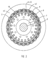
- FIG. 1 is on the rotor shaft 2 of the rotor 1 of an electrical machine, for example an asynchronous machine, a rotor core 3, consisting made of dynamo sheets, pressed on, both sides of the rotor sheet stack Support rings 7, 8, end plates or end plates are provided, which are firmly connected to the rotor shaft, e.g. are shrunk onto them.
- a squirrel cage are several rotor bars axially through the rotor laminated core 4, in particular made of copper, the front rotor bars 4 ', 4' 'protruding from the rotor laminated core electrically and mechanically connected to short-circuit rings 5, 6 are.
- Cooling air holes 9 can be guided through the rotor laminated core.
- the electric machine further includes one under formation a cylindrical gap 16 arranged around the rotor 1 Stand 10.
- the stand 10 consists of a stator core 10 ', in which a plurality of stator coils 11 are arranged, wherein from the stator core package with coil legs the stator coil end windings 12, 13 are led out.
- rotor 1 is a shield 14, 15 or 14 'provided.
- deposits form 14 ', bridging elements or filler pieces between the coil legs or winding heads 12, 13 of the stator core 10 'die for a smooth surface in the winding head inside diameter of the stand 10 provides shielding against the rotating Runner parts 4 ', 4' ', 5, 6.
Abstract
Zur Reduzierung des Schalleistungspegels einer elektrischen Maschine mit Betriebs- oder Dämpferkäfig wird eine Abschirmung (14, 15; 14') des Ständers (10) im Bereich der über das Läuferblechpaket (3) überstehenden Läuferstabenden (4', 4'') vorgeschlagen. <IMAGE>To reduce the sound power level of an electrical machine with an operating or damper cage, a shield (14, 15; 14 ') of the stator (10) is proposed in the area of the rotor bars (4', 4 '') projecting beyond the rotor laminated core (3). <IMAGE>
Description
Die Erfindung betrifft eine elektrische Maschine mit einem auf einer Läuferwelle angeordneten Läuferblechpaket, in dem Läuferstäbe angeordnet sind, welche an den an den Stirnseiten des Läuferblechpaketes überstehenden Läuferstabenden durch je einen Kurzschlußring elektrisch und mechanisch miteinander verbunden sind und mit einem durch einen zylindrischen Spalt vom Läuferblechpaket getrennten Ständerblechpaket, das mit Ständerspulen bestückt ist, die stirnseitig aus dem Ständerblechpaket ragende Ständerspulen-Wickelköpfe bilden.The invention relates to an electrical machine with a rotor laminated core arranged on a rotor shaft, in which Runner bars are arranged, which on the end faces of the runner sheet stack protruding runner bars by each a short-circuit ring electrically and mechanically with each other are connected and with a through a cylindrical gap separate from the rotor laminated core package, the with Stator coils is assembled, the front of the stator core form protruding stator coil winding heads.
Als elektrische Maschinen dieser Art kommen Synchronmaschinen mit Dämpferkäfig und Asynchronmaschinen mit Käfigläufer in Betracht. Eine Asynchronmaschine dieser Art ist aus der DE-40 14 116 A1 bekannt.Synchronous machines come as electrical machines of this type with damper cage and asynchronous machines with cage rotor in Consideration. An asynchronous machine of this type is from DE-40 14 116 A1 known.
Aus der DE 195 25 704 C1 ist ein gekapselter Rotor für einen Asynchronmotor als Naßlaufmotor zum Antrieb einer Kreispumpe bekannt. Hierbei ist das Rotorblechpaket durch einen korrosionsfesten Schutzmantel gegenüber der Kühlflüssigkeit geschützt. Ferner ist aus der DE-40 03 155 A1 eine fremdbelüftete elektrische Maschine mit Klauenpolläufer bekannt, wobei zur Bildung von Luftleitkanälen Ringwände aus Kunststoff zwischen dem Ständerblechpaket und den Lagerschilden angeordnet sind. Schließlich ist es bei einem Kollektormotor für Hausgeräte zur Geräuschminderung aus der DE-87 12 026.7 U1 bekannt, das Läufer- und/oder Ständerblechpaket durch Umwickeln mit Kunststoffolie mit glatten Mantelflächen zu versehen.DE 195 25 704 C1 describes an encapsulated rotor for one Asynchronous motor as a wet-running motor for driving a circular pump known. Here, the rotor core is made of a corrosion-resistant Protective jacket protected against the coolant. Furthermore, DE-40 03 155 A1 is a forced ventilation known electrical machine with claw-pole rotor, whereby to form air ducts plastic ring walls between the stator core and the end shields arranged are. After all, it is with a collector motor for household appliances known from DE-87 12 026.7 U1 for noise reduction, the runner and / or stator core by wrapping with To provide plastic film with smooth outer surfaces.
Aus der DE-A-23 61 764 ist eine Asynchronmaschine mit Käfigläufer bekannt, wobei in Nuten des Läuferblechpaketes insbesondere aus Kupfer bestehende Läuferstäbe angeordnet sind, deren stirnseitig über das Läuferblechpaket überstehende Läuferstabenden durch je einen Kurzschlußring elektrisch und mechanisch miteinander verbunden sind. Auf der Läuferwelle ist das Läuferblechpaket zwischen Stützringen oder Endscheiben gehalten. Der Läufer rotiert im Abstand eines zylindrischen Spaltes in der Bohrung des Ständerblechpaketes des Ständers, wobei in Nuten des Ständerblechpaketes Ständerspulen angeordnet sind, die stirnseitig aus dem Ständerblechpaket ragende Ständerspulen-Wickelköpfe bilden.DE-A-23 61 764 describes an asynchronous machine with a squirrel-cage rotor known, in particular in grooves of the rotor core rotor bars made of copper are arranged, whose end faces protrude beyond the rotor laminated core each with a short-circuit ring, electrically and mechanically are interconnected. Is on the rotor shaft the rotor laminated core between support rings or end plates held. The rotor rotates at a cylindrical distance Gap in the hole of the stator core, where stator coils are arranged in the slots of the stator core are protruding from the stator core Form stator coil ends.
Bei schnell laufenden Maschinen sind besonders die beidseits aus dem Läuferblechpaket ragenden Läuferstabenden und die mit ihnen verbundenen Kurzschlußringe stark beansprucht. Im Zusammenwirken mit den beidseits aus dem Ständerblechpaket ragenden Ständerspulen bzw. Ständerspulen-Wickelköpfen entstehen aufgrund der Rotation der Läuferstabenden gegenüber den Spulenschenkeln bzw. Wickelköpfen hohe störende Geräusche. Um diesen Nachteilen zu begegnen, hat man bereits versucht, den Abstand zwischen den Endscheiben des Läuferblechpaketes und den Kurzschlußringen klein zu halten. Dies führt jedoch zu einer Verschlechterung der Kühlung des Läufers. Gemäß der EP-0 749 198 A2 sind zur Dämpfung der Eigenschwingungen des Käfigläufers einer Asynchronmaschine beidseits des Läuferblechpaketes Distanzstege und vorzugsweise mit diesen einstückig ausgebildete Stützringe vorgesehen, derart, daß jeder Kurzschlußring in radialer Richtung durch einen auf der Läuferwelle festsitzenden Stützring abgestützt ist und der Kurzschlußring durch einen zugeordneten Schrumpfring, der den Kurzschlußring umgibt, auf den Stützring gepreßt wird. Auch ein relativ aufwendiger Kurzschlußläufer dieser Art arbeitet bei höheren Drehzahlen mit relativ starkem Laufgeräusch.In the case of high-speed machines, they are particularly double-sided runners sticking out of the rotor laminated core and those with short-circuit rings associated with them are highly stressed. In cooperation with the protruding from both sides of the stator core Stator coils or stator coil winding heads are created due to the rotation of the runner bars compared to the Bobbin legs or winding heads high annoying noises. Around To overcome these disadvantages, one has already tried to Distance between the end plates of the rotor core and to keep the short-circuit rings small. However, this leads to deterioration in cooling of the rotor. According to EP-0 749 198 A2 are for damping the natural vibrations of the cage rotor an asynchronous machine on both sides of the rotor laminated core Spacers and preferably in one piece with them trained support rings provided, such that each short-circuit ring in the radial direction by one on the rotor shaft tight support ring is supported and the short-circuit ring by an associated shrink ring that the Short-circuit ring surrounds, is pressed onto the support ring. Also a relatively complex short-circuit rotor of this type works at higher speeds with relatively strong running noise.
Aufgabe der Erfindung ist es, bei einer elektrischen Maschine der eingangs genannten Art den Schalleistungspegel zu reduzieren. The object of the invention is in an electrical machine of the type mentioned at the outset to reduce the sound power level.
Diese Aufgabe wird erfindungsgemäß durch die im Patentanspruch
1 bzw. 4 angegebenen Merkmale gelöst. Der Vorteil der
Erfindung ist insbesondere darin zu sehen, daß die Abschirmung
die zur Geräuschbildung führenden Kanten oder Vorsprünge
zwischen den rotierenden Läuferstabenden und den Spulenschenkeln
bzw. Wickelköpfen des Ständerblechpaketes vermeidet
und eine relativ glatte Oberfläche der Ständerköpfe im Bereich
der aus dem Ständerblechpaket ragenden Spulenschenkel
und Wickelköpfe bildet.This object is achieved by the
Eine vorteilhafte Ausgestaltung der Erfindung ist durch die
Merkmale des Patentanspruches 2 gekennzeichnet. Eine weitere
Ausführung der Erfindung besteht darin, daß die Ringe zylindrisch
sind, die etwa in axialer Verlängerung der Ständerblechpaketbohrung
zwischen Ständer und Läufer Strömungskanten
an den Ständerspulen-Wickelköpfen vermeiden.An advantageous embodiment of the invention is the
Features of
Nach einer anderen Ausführung der Erfindung ist vorgesehen, daß zwishen den Wickelköpfen der Ständerspulen über den Umfang des Ständers Einlagen, Überbrückungselemente, Füllstücke od.dgl. vorgesehen sind, die einen im wesentlichen zylindrisch bis kegelförmig verlaufenden, geschlossenen Wickelkopfdurchmesser bilden, in dem die Läuferstabenden und Kurzschlußringe des Läufers rotieren.According to another embodiment of the invention, that between the winding heads of the stator coils over the circumference of the stand deposits, bridging elements, filler pieces or the like. are provided, which are substantially cylindrical up to a conical, closed winding end diameter form in which the runner bars and short-circuit rings of the runner rotate.
Ausführungsbeispiele der Erfindung sowie weitere damit verbundene Vorteile werden nachfolgend anhand der Zeichnung näher erläutert.Embodiments of the invention and other related Advantages will become more apparent from the drawing explained.
Es zeigen:
Bei dem Ausführungsbeispiel nach Figur 1 ist auf die Läuferwelle
2 des Läufers 1 einer elektrischen Maschine, beipielsweise
einer Asynchronmaschine, ein Läuferblechpaket 3, bestehend
aus Dynamoblechen, aufgepreßt, wobei beidseits des Läuferblechpaketes
Stützringe 7, 8, Endscheiben oder Endplatten
vorgesehen sind, welche mit der Läuferwelle fest verbunden,
z.B. auf diese aufgeschrumpft sind. In der Ausbildung als Käfigläufer
sind axial durch das Läuferblechpaket mehrere Läuferstäbe
4, insbesondere aus Kupfer, geführt, deren stirnseitig
aus dem Läuferblechpaket ragende Läuferstabenden 4', 4''
elektrisch und mechanisch mit Kurzschlußringen 5, 6 verbunden
sind. Zur Kühlung des Läufers 1 können z.B. mehrere axiale
Kühlluftbohrungen 9 durch das Läuferblechpaket geführt sein.In the embodiment of Figure 1 is on the
Die elektrische Maschine umfaßt ferner einen unter Bildung
eines zylindrischen Spaltes 16 um den Läufer 1 angeordneten
Ständer 10. Der Ständer 10 besteht aus einem Ständerblechpaket
10', in dem mehrere Ständerspulen 11 angeordnet sind, wobei
stirnseitig aus dem Ständerblechpaket Spulenschenkel mit
den Ständerspulen-Wickelköpfen 12, 13 herausgeführt sind.The electric machine further includes one under formation
a
Zur Bildung einer geräuschmindernden glatten Oberfläche zwischen
den Wickelköpfen 12, 13 des Ständers 10 und den rotierenden
Läuferstabenden 4', 4'' und Kurzschlußringen 5, 6 des
Läufers 1 ist erfindungsgemäß eine Abschirmung 14, 15 bzw.
14' vorgesehen.To form a noise reducing smooth surface between
the
Bei der Ausführung nach den Figuren 1 und 2 wird die Abschirmung
durch stirnseitig am Ständer 10 angeordnete Ringe 14,
15, Buchsen oder Hülsen gebildet, die vorzugsweise aus isolierendem
Material bestehen. Dabei bildet die Abschirmung des
Ständers zylindrisch bis kegelförmig verlaufende ringförmige
Teile für einen geschlossenen Wickelkopfinnendurchmesser.
Diese Ausbildung vermeidet geräuschbildende Kanten gegenüber
den rotierenden Teilen 4', 4'', 5, 6 des Läufers 1.In the embodiment according to Figures 1 and 2, the shield
by
Gemäß dem Ausführungsbeispiel der Figur 3 bilden Einlagen
14', Überbrückungselemente oder Füllstücke zwischen den Spulenschenkeln
bzw. Wickelköpfen 12, 13 des Ständerblechpaketes
10' die für eine glatte Oberfläche im Wickelkopfinnendurchmesser
des Ständers 10 sorgende Abschirmung gegenüber den rotierenden
Läuferteilen 4', 4'', 5, 6. Mittels der erfindungsgemäßen
Abschirmung ist eine wesentliche Absenkung des Schalleistungspegels
der elektrischen Maschine möglich.According to the exemplary embodiment in FIG. 3, deposits form
14 ', bridging elements or filler pieces between the coil legs
or
Claims (5)
Applications Claiming Priority (2)
| Application Number | Priority Date | Filing Date | Title |
|---|---|---|---|
| DE1997141200 DE19741200C1 (en) | 1997-09-18 | 1997-09-18 | Electrical machine stator/rotor arrangement e.g. for asynchronous machine |
| DE19741200 | 1997-09-18 |
Publications (1)
| Publication Number | Publication Date |
|---|---|
| EP0903833A1 true EP0903833A1 (en) | 1999-03-24 |
Family
ID=7842833
Family Applications (1)
| Application Number | Title | Priority Date | Filing Date |
|---|---|---|---|
| EP98116861A Withdrawn EP0903833A1 (en) | 1997-09-18 | 1998-09-07 | Electrical machine with squirrel cage rotor |
Country Status (2)
| Country | Link |
|---|---|
| EP (1) | EP0903833A1 (en) |
| DE (1) | DE19741200C1 (en) |
Cited By (1)
| Publication number | Priority date | Publication date | Assignee | Title |
|---|---|---|---|---|
| EP3598618A1 (en) * | 2018-07-19 | 2020-01-22 | Siemens Mobility GmbH | Dynamoelectric rotary machine with elements for reducing of tonal noise |
Families Citing this family (4)
| Publication number | Priority date | Publication date | Assignee | Title |
|---|---|---|---|---|
| FR2903245B1 (en) * | 2006-06-28 | 2015-03-27 | Valeo Equip Electr Moteur | STATOR FOR ROTATING ELECTRIC MACHINE AND ROTATING ELECTRIC MACHINE COMPRISING SUCH A STATOR |
| ES2364214T3 (en) | 2008-02-27 | 2011-08-29 | Alstom Technology Ltd | COOLING BY FAN OF AN ELECTRIC MOTOR. |
| EP2528204B1 (en) * | 2011-05-27 | 2017-12-27 | ABB Schweiz AG | Solid squirrel-cage rotor for an induction machine and manufacturing method thereof |
| EP3544154A1 (en) * | 2018-03-19 | 2019-09-25 | Siemens Aktiengesellschaft | Dynamoelectric rotary machine with slot covers |
Citations (4)
| Publication number | Priority date | Publication date | Assignee | Title |
|---|---|---|---|---|
| US4546279A (en) * | 1984-05-07 | 1985-10-08 | Westinghouse Electric Corp. | Dynamoelectric machine with rotor ventilation system including exhaust coolant gas diffuser and noise baffle |
| EP0269558A2 (en) * | 1986-11-24 | 1988-06-01 | Tecnodelta S.A. | Electric arbor integrated with an induction motor and process for its production |
| GB2239128A (en) * | 1989-10-31 | 1991-06-19 | Mitsubishi Electric Corp | Noise reduction in air cooled induction rotary electric machine |
| JPH07288944A (en) * | 1994-04-13 | 1995-10-31 | Meidensha Corp | Ventilation-noise preventing structure of induction motor |
Family Cites Families (6)
| Publication number | Priority date | Publication date | Assignee | Title |
|---|---|---|---|---|
| CH560479A5 (en) * | 1972-12-19 | 1975-03-27 | Asea Ab | |
| DE8712026U1 (en) * | 1987-09-04 | 1988-07-07 | Siemens Ag, 1000 Berlin Und 8000 Muenchen, De | |
| DE4003155A1 (en) * | 1990-02-03 | 1991-08-29 | Bosch Gmbh Robert | ELECTRIC MACHINE WITH FOREIGN VENTILATION |
| DE4014116A1 (en) * | 1990-05-02 | 1991-11-07 | Loher Ag | Asynchronous electrical machine - has rotor short-circuit ring enclosed on three sides by magnetically conductive ring to reduce switching-in currents |
| DE19521700A1 (en) * | 1995-06-14 | 1996-12-19 | Abb Daimler Benz Transp | Squirrel cage for an asynchronous machine |
| DE19525704C1 (en) * | 1995-07-14 | 1996-07-25 | Grundfos As | Encapsulated rotor for asynchronous motor in circulation pump |
-
1997
- 1997-09-18 DE DE1997141200 patent/DE19741200C1/en not_active Expired - Fee Related
-
1998
- 1998-09-07 EP EP98116861A patent/EP0903833A1/en not_active Withdrawn
Patent Citations (4)
| Publication number | Priority date | Publication date | Assignee | Title |
|---|---|---|---|---|
| US4546279A (en) * | 1984-05-07 | 1985-10-08 | Westinghouse Electric Corp. | Dynamoelectric machine with rotor ventilation system including exhaust coolant gas diffuser and noise baffle |
| EP0269558A2 (en) * | 1986-11-24 | 1988-06-01 | Tecnodelta S.A. | Electric arbor integrated with an induction motor and process for its production |
| GB2239128A (en) * | 1989-10-31 | 1991-06-19 | Mitsubishi Electric Corp | Noise reduction in air cooled induction rotary electric machine |
| JPH07288944A (en) * | 1994-04-13 | 1995-10-31 | Meidensha Corp | Ventilation-noise preventing structure of induction motor |
Non-Patent Citations (1)
| Title |
|---|
| PATENT ABSTRACTS OF JAPAN vol. 096, no. 002 29 February 1996 (1996-02-29) * |
Cited By (2)
| Publication number | Priority date | Publication date | Assignee | Title |
|---|---|---|---|---|
| EP3598618A1 (en) * | 2018-07-19 | 2020-01-22 | Siemens Mobility GmbH | Dynamoelectric rotary machine with elements for reducing of tonal noise |
| US11539275B2 (en) | 2018-07-19 | 2022-12-27 | Siemens Mobility GmbH | Dynamoelectric rotary machine with elements for reducing tonal noises |
Also Published As
| Publication number | Publication date |
|---|---|
| DE19741200C1 (en) | 1999-01-21 |
Similar Documents
| Publication | Publication Date | Title |
|---|---|---|
| EP2368308B1 (en) | Electrical motor havingaxial and radially offsetted cooling stream and related method | |
| DE102008064495B3 (en) | Electric machine with several cooling streams and cooling process | |
| EP2109207B1 (en) | Liquid cooled electric machine and process for cooling an electric machine | |
| WO2020099048A1 (en) | Support device for a rotor of a separately excited internal-rotor synchronous machine consisting of a support ring and a star disc | |
| DE69804284T3 (en) | vehicle generator | |
| EP1203436B1 (en) | Electric axial flow machine | |
| WO2008077855A1 (en) | Pm rotor having radial cooling slots and corresponding method of production | |
| DE102005016856A1 (en) | Electric asynchronous machine with tooth coils in the stator winding system | |
| DE102009010475B4 (en) | Winding fixing component and rotating electrical machine equipped therewith | |
| DE2334637B2 (en) | Pass-through ventilated electric machine | |
| DE10153578B4 (en) | Alternator for permanent magnet vehicles in the rotor and method of making same | |
| DE1939184A1 (en) | Arrangement for cooling the rotors of electrical machines, in particular small electric motors | |
| DE69826907T2 (en) | electric motor | |
| DE60201937T2 (en) | Electric machine with external rotor | |
| EP2162971B1 (en) | Stator with insulation for an electric motor and insulation for a stator as well as electric machine tool | |
| DE102005058249B4 (en) | Magnetoelectric generator | |
| EP0903833A1 (en) | Electrical machine with squirrel cage rotor | |
| DE3314426A1 (en) | LEG POLLAR FOR AN ELECTRICAL ROTATION MACHINE | |
| EP3084927B1 (en) | Rotor of a rotating electric machine | |
| DE19927279A1 (en) | Squirrel-cage rotor design e.g. for railway high-speed asynchronous machine | |
| DE102021100847A1 (en) | electrical machine | |
| EP1065779B1 (en) | Electric air-cooled machine | |
| DE102020202337A1 (en) | Laundry care device with electric drive | |
| EP3326266B1 (en) | High-speed motor with air gap winding | |
| DE102019218445A1 (en) | Electric machine with rotor cooling and motor vehicle |
Legal Events
| Date | Code | Title | Description |
|---|---|---|---|
| PUAI | Public reference made under article 153(3) epc to a published international application that has entered the european phase |
Free format text: ORIGINAL CODE: 0009012 |
|
| AK | Designated contracting states |
Kind code of ref document: A1 Designated state(s): AT DE ES FR GB |
|
| AX | Request for extension of the european patent |
Free format text: AL;LT;LV;MK;RO;SI |
|
| 17P | Request for examination filed |
Effective date: 19990419 |
|
| AKX | Designation fees paid |
Free format text: AT DE ES FR GB |
|
| 17Q | First examination report despatched |
Effective date: 19991223 |
|
| STAA | Information on the status of an ep patent application or granted ep patent |
Free format text: STATUS: THE APPLICATION HAS BEEN WITHDRAWN |
|
| 18W | Application withdrawn |
Withdrawal date: 20000323 |