EP0903827B1 - Interface de câblage - Google Patents
Interface de câblage Download PDFInfo
- Publication number
- EP0903827B1 EP0903827B1 EP19970202869 EP97202869A EP0903827B1 EP 0903827 B1 EP0903827 B1 EP 0903827B1 EP 19970202869 EP19970202869 EP 19970202869 EP 97202869 A EP97202869 A EP 97202869A EP 0903827 B1 EP0903827 B1 EP 0903827B1
- Authority
- EP
- European Patent Office
- Prior art keywords
- integration
- wire
- separation
- wiring
- disconnects
- Prior art date
- Legal status (The legal status is an assumption and is not a legal conclusion. Google has not performed a legal analysis and makes no representation as to the accuracy of the status listed.)
- Expired - Lifetime
Links
- 238000000926 separation method Methods 0.000 claims description 47
- 230000010354 integration Effects 0.000 claims description 39
- 238000009826 distribution Methods 0.000 claims description 13
- 238000000034 method Methods 0.000 claims description 12
- 230000008878 coupling Effects 0.000 claims description 2
- 238000010168 coupling process Methods 0.000 claims description 2
- 238000005859 coupling reaction Methods 0.000 claims description 2
- 230000013011 mating Effects 0.000 claims 2
- 238000005315 distribution function Methods 0.000 claims 1
- 230000007257 malfunction Effects 0.000 claims 1
- 238000009434 installation Methods 0.000 description 4
- 238000004519 manufacturing process Methods 0.000 description 3
- 101001005165 Bos taurus Lens fiber membrane intrinsic protein Proteins 0.000 description 2
- 230000000712 assembly Effects 0.000 description 2
- 238000000429 assembly Methods 0.000 description 2
- 230000002093 peripheral effect Effects 0.000 description 2
- 239000000306 component Substances 0.000 description 1
- 238000010586 diagram Methods 0.000 description 1
- 239000000835 fiber Substances 0.000 description 1
- 239000006260 foam Substances 0.000 description 1
- 239000000446 fuel Substances 0.000 description 1
- 239000011159 matrix material Substances 0.000 description 1
- 230000007935 neutral effect Effects 0.000 description 1
- 239000003921 oil Substances 0.000 description 1
- 230000003287 optical effect Effects 0.000 description 1
- 239000013307 optical fiber Substances 0.000 description 1
- 238000005457 optimization Methods 0.000 description 1
- 230000001681 protective effect Effects 0.000 description 1
- 230000001012 protector Effects 0.000 description 1
Images


Classifications
-
- H—ELECTRICITY
- H01—ELECTRIC ELEMENTS
- H01R—ELECTRICALLY-CONDUCTIVE CONNECTIONS; STRUCTURAL ASSOCIATIONS OF A PLURALITY OF MUTUALLY-INSULATED ELECTRICAL CONNECTING ELEMENTS; COUPLING DEVICES; CURRENT COLLECTORS
- H01R31/00—Coupling parts supported only by co-operation with counterpart
Definitions
- the present invention relates to wiring installations and more particularly to wiring installations in aircraft electronics bays, main instrument panels or overhead panels which require extremely complex wiring of multiple systems.
- U.S. patent No. 4,320,261 to Scerbo, et al shows a method for optimizing cable routing in the distribution panels for an office environment. Means are described for minimizing crossovers and cable lengths. Optimization is based on crossovers and length in contrast to the present method which considers separation requirements. Also Scerbo, et al, is hardwired in contrast to the present method of using connectors.
- US 4 776 529 discloses a method of using heat pads to preheat helicopter metallic components, oils and fuel.
- the heat pads are connected by a power cord to an electric source.
- the power cord follows the route of existing wire bundles. There is no redundancy to prevent simultaneously failure of heat pads.
- the connectors are used to connect the heat pads to the harness and the harness to a power source. If a cable was severed, all signals to the heat pad would fail casuing complete failure of the system.
- US 5 659 655 discloses a box for protecting Berg fiber optic fanouts, wherein a Berg-method is used to fanout and splice optical fibre cables with minimal optical loss. This document provides a method to protect the Berg fanout. If a cable was severed, all signals would fail causing complete failure of the system.
- a plural level wiring interface system and a method of providing such a plural level wiring interface comprising the features of claim 1 and 4.
- This invention employs a plural-level system to achieve simplicity.
- Each panel is analyzed to assign wire separation categories for every required connection and then one or more connectors (designated separation dedicated connectors) is incorporated for each category.
- the opposite end of the system is composed of a set of "integration disconnects".
- the connections on these are determined by performing a wire separation category analysis on the wires coming into the instrument bay from the peripherals in a given physical area (called a destination area) and assigning at least one connector for each category.
- the third portion of the system is composed of the "integration wire bundles". These are designed with breakouts from the bundle body so that they connect the proper terminals of the dedicated separation connectors to the proper terminals of the integration disconnects.
- the present invention solves the separation problem by utilizing separation dedicated connectors.
- a wire is inserted into the connector meeting the wires separation requirement; should multiple connectors meet the wire's separation requirement, the wire is inserted into the connector also meeting the wire's destination requirements, thereby providing a solution to the separation routing congestion, cross-connected wire bundles, and complexity problems.
- a wiring matrix results in simplified discrete integrated wire bundles which are assembled and positioned on the module or overhead panel before final assembly thereby completing a module or panel and wiring assembly.
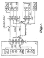
- Routing integration previously achieved by end point aircraft final assembly wiring with complex integration wiring panels is eliminated in accordance with the present plural level wiring interface hereinafter described utilization which is a system utilizing separation dedicated connectors, integration disconnects (having no wiring, Ref. Fig. 4A and 4B), Ref. Fig. 1 and 2, modular integrated wire bundles and panels, destination dedicated connectors, and wire bundle breakouts from the bundle body (Ref. Fig. 1, 3A and 3B.
- the present system permits wire bundle production on foam boards including connectors and wiring as integral unitary modules.
- the separation categories in the module or panel are determined; A,B,C, and N for example, where N is a neutral or non-critical separation; and for example Separation A is routed on the left side, B is routed on the right side, and C is redundant to A and/or B and routed away from A and B.
- the module or panel is assigned a connector for each separation category in the module or panel.
- MP2 is assigned separation connectors A,B,C
- MP3 is assigned separation connectors B, & C
- MP1 is assigned separation connector A/N (since separation category N may be combined with any other separation category).
- the internal wiring of the modules or panels are separation routed and connected to the separation dedicated connectors of the module or panel interface.
- Integration wire bundles IB1, IB2, IB3 are used to route wires of similar separation from the module or panel separation dedicated connector interface to an integration disconnect ID1 via breakouts from the bundle body. Wires from separation dedicated connectors; A of MP2 and A/N of MP1 are combined into IB1; B of MP2 and MP3 are combined into IB2; and C of MP2 and MP3 are combined into IB3.
- Integration wire bundles IB1, IB2, and IB3 are kept separate from each other and routed to an integration disconnect ID1. (Thus a failure in one bundle will not affect the wiring in another bundle.).
- This integration disconnect is close to or part of the module or panel assembly E1.
- the integration disconnect provides a disconnect for the assembly E1 as well as an integration interface to the distribution wire bundles.
- IB1 mates with connector 1 (separation dedicated A/N) and connector 2 (separation dedicated N); [Note:
- the integration disconnect connector 2 is used to route a portion of the separation N wires based on destination, and eliminates the need for wiring at the integration disconnect to enter another distribution wire bundle, Ref. Fig. 4A and 4B).
- IB2 mates directly with DB2 and provides a disconnect function at connector 3.
- IB3 mates with connectors 4 and 5 to accommodate the volume of wires and provide the disconnect function.
- the distribution wire bundles are used to make long runs with breakouts from the bundle body (Ref. Fig. 1) to other integration or destination areas.
- DB1 routes separation category A wires direct from ID1 to ID2; (integration disconnect, ID2, is shown being used as a production break interface).
- DB2 routes separation category B wires to both ID2 and ID3 (ID3 being shown as an integration disconnect interface on an enclosed assembly E2).
- DB3 accepts separation category N wires from IB1 for routing to destination device D5 having a single C/N separation dedicated connector; DB3 also has routing breakouts from the bundle body (Ref. Fig. 1) for separation category C wiring to ID2 and ID3.
- FIG 2A there is seen a plural level wiring interface of the kind shown in Figure 1 however as adapted for an overhead panel. Only the elements of the present system are shown in heavy lines.
- Separation categories D and E represent (in air/in space/at sea) and (on ground/at port) usage respectively, exclusive usage allows the combining of these,wires into a single connector.
- Separation categories F and G are redundant to categories A and B, and may be combined (provided they have protective shielding from A and B) to the first distribution breakout.
- Figure 2A is a detail of a complex panel, thus destination devices are not shown.
- Modules MP22 and MP23 interface with both integration and distribution wire bundles.
- Connectors (1,2,3), (4,5,6), and (10,11,12) are provided to handle the volume of wires.
- Connectors 8 and 9 on integration disconnect ID1A are provided to separate and distribute separation category D and E wires.
- Connectors 7 and 13 on integration disconnects ID1A and ID1B are provided to separate and distribute separation category A and B from F and G.
- Connectors 1 thru 19 also provide a panel disconnect function.
Landscapes
- Structure Of Telephone Exchanges (AREA)
Claims (4)
- Système d'interface de câblage à plusieurs niveaux afin d'effectuer des connexions de circuits électriques entre un premier ensemble de bornes (MP1 A/N, MP2 A, B, C, MP3 B, C) et un dernier ensemble de bornes (D1 A/N, D2 A, D3 B, C, D4 B, C, D5 C/N), comprenant :une pluralité de connecteurs spécialisés de catégorie de séparation, par l'intermédiaire desquels des fils sont séparés et acheminés pour empêcher un dysfonctionnement d'un système, qui sont couplés auxdits premier et dernier ensembles de bornes ;une pluralité de déconnexions d'intégration couplées dans ledit système d'interface de câblage avec des ensembles intermédiaires de bornes (1-10) ;et un ensemble de faisceaux de fils d'intégration (IB1-IB3) pour assurer une fonction d'intégration, et des faisceaux de fils de répartition (DB-DB3) afin d'assurer une fonction de répartition, comprenant une utilisation de séparations de fils à partir d'un couplage de corps de faisceau entre ladite pluralité de connecteurs spécialisés de séparation et ladite pluralité de déconnexions d'intégration.
- Système d'interface de câblage à plusieurs niveaux selon la revendication 1, dans lequel lesdites déconnexions d'intégration n'ont pas de câblage interne.
- Système d'interface de câblage à plusieurs niveaux selon la revendication 1, dans lequel la structure de séparations de fils comporte un ou plusieurs fils pénétrant dans ou quittant le corps de faisceau.
- Procédé de réalisation d'un système d'interface à plusieurs niveaux afin de connecter des faisceaux de fils pour éliminer des zones d'intégration de câblage, comprenant les étapes consistant à :prévoir une pluralité de faisceaux de fils d'intégration comprenant des séparations de fils depuis le corps du faisceau, contenant des fils entre des connecteurs spécialisés de catégorie de séparation et des déconnexions d'intégration ;prévoir une pluralité de faisceaux de fils de répartition, contenant des fils entre des déconnexions d'intégration ;adapter une fiche de connecteur d'un faisceau de fils d'intégration directement au réceptacle du connecteur d'un faisceau de fils de répartition de telle sorte que chacune de ladite pluralité de déconnexions d'intégration n'ait pas de câblage entre les connecteurs de faisceaux en regard.
Priority Applications (2)
| Application Number | Priority Date | Filing Date | Title |
|---|---|---|---|
| DE1997614252 DE69714252T2 (de) | 1997-09-18 | 1997-09-18 | Verdrahtungsschnittstelle |
| EP19970202869 EP0903827B1 (fr) | 1997-09-18 | 1997-09-18 | Interface de câblage |
Applications Claiming Priority (1)
| Application Number | Priority Date | Filing Date | Title |
|---|---|---|---|
| EP19970202869 EP0903827B1 (fr) | 1997-09-18 | 1997-09-18 | Interface de câblage |
Publications (2)
| Publication Number | Publication Date |
|---|---|
| EP0903827A1 EP0903827A1 (fr) | 1999-03-24 |
| EP0903827B1 true EP0903827B1 (fr) | 2002-07-24 |
Family
ID=8228736
Family Applications (1)
| Application Number | Title | Priority Date | Filing Date |
|---|---|---|---|
| EP19970202869 Expired - Lifetime EP0903827B1 (fr) | 1997-09-18 | 1997-09-18 | Interface de câblage |
Country Status (2)
| Country | Link |
|---|---|
| EP (1) | EP0903827B1 (fr) |
| DE (1) | DE69714252T2 (fr) |
Families Citing this family (2)
| Publication number | Priority date | Publication date | Assignee | Title |
|---|---|---|---|---|
| FR2822130B1 (fr) * | 2001-03-14 | 2003-06-27 | Labinal | Avion comportant un cablage electrique |
| CN115864051B (zh) * | 2022-11-29 | 2026-01-02 | 沈阳兴华航空电器有限责任公司 | 一种多线路悬挂系统电缆装置 |
Family Cites Families (7)
| Publication number | Priority date | Publication date | Assignee | Title |
|---|---|---|---|---|
| US2098321A (en) | 1935-06-07 | 1937-11-09 | Bell Telephone Labor Inc | Distributing frame |
| GB1324563A (en) * | 1971-03-03 | 1973-07-25 | British Insulated Callenders | Multi-conductor electric cables |
| US4320261A (en) | 1980-10-03 | 1982-03-16 | Bell Telephone Laboratories, Incorporated | Cable routing methods and apparatus |
| US4583215A (en) | 1984-03-30 | 1986-04-15 | Itt Corporation | Telephone line access system for main distribution frame |
| US4776529A (en) * | 1986-08-06 | 1988-10-11 | Tanis Peter G | Helicopter preheat assembly |
| US4972298A (en) | 1989-09-08 | 1990-11-20 | International Business Machines Corporation | High density circuit assembly |
| US5659655A (en) * | 1996-04-29 | 1997-08-19 | Mcdonnell Douglas Corporation | Optical ribbon cable fanout boxes |
-
1997
- 1997-09-18 DE DE1997614252 patent/DE69714252T2/de not_active Expired - Lifetime
- 1997-09-18 EP EP19970202869 patent/EP0903827B1/fr not_active Expired - Lifetime
Also Published As
| Publication number | Publication date |
|---|---|
| EP0903827A1 (fr) | 1999-03-24 |
| DE69714252D1 (de) | 2002-08-29 |
| DE69714252T2 (de) | 2002-11-21 |
Similar Documents
| Publication | Publication Date | Title |
|---|---|---|
| US5340326A (en) | Connectivity management system | |
| US5149277A (en) | Connectivity management system | |
| EP0726528B1 (fr) | Réseau d'interconnexion pour un système de traitement de données multi-nodal | |
| US6554639B2 (en) | Wiring interface | |
| CA2621016C (fr) | Tableau de conversion de media a signal numerique | |
| JP4041985B2 (ja) | 複数のプロセッサを収容するシャシ装置で使用する単純構造電力及びデータコネクタ | |
| US8275228B2 (en) | Network interface unit for modular furniture | |
| US5719933A (en) | Wiring arrangement for a communication interconnection system | |
| US5789710A (en) | Reduced cross-talk wiring harness and method of accomplishing same | |
| JPH0896900A (ja) | コネクタモジュール | |
| EP0903827B1 (fr) | Interface de câblage | |
| GB2199196A (en) | Flat cable transmission system | |
| US6299490B1 (en) | Communication system and communication cable connector assembly | |
| US20020044026A1 (en) | Method and apparatus for distribution of power in a media converter system | |
| US5698821A (en) | Cable assembly | |
| US20010041473A1 (en) | Wiring interface | |
| CA2214808A1 (fr) | Interface de cablage | |
| CN217639656U (zh) | 一种光纤布线模块以及网络设备 | |
| CN116897476A (zh) | 模块化电连接装置 | |
| US20250347883A1 (en) | Fiber optic cassette configured to receive a multifiber connector that is configured to provide network redundancy and/or increased fiber density | |
| EP3405826B1 (fr) | Module de terminaison et ensemble de terminaison comprenant ledit module de terminaison | |
| CN1166065A (zh) | 插件板的连接方法及其结构 | |
| CA2010865C (fr) | Systeme de gestion de connectivite | |
| JP2761337B2 (ja) | 電力配線統合hub | |
| US6074254A (en) | Communication system and communication cable connector assembly |
Legal Events
| Date | Code | Title | Description |
|---|---|---|---|
| PUAI | Public reference made under article 153(3) epc to a published international application that has entered the european phase |
Free format text: ORIGINAL CODE: 0009012 |
|
| AK | Designated contracting states |
Kind code of ref document: A1 Designated state(s): DE FR GB |
|
| AX | Request for extension of the european patent |
Free format text: AL;LT;LV;RO;SI |
|
| 17P | Request for examination filed |
Effective date: 19990915 |
|
| AKX | Designation fees paid |
Free format text: DE FR GB |
|
| 17Q | First examination report despatched |
Effective date: 20000811 |
|
| GRAG | Despatch of communication of intention to grant |
Free format text: ORIGINAL CODE: EPIDOS AGRA |
|
| GRAG | Despatch of communication of intention to grant |
Free format text: ORIGINAL CODE: EPIDOS AGRA |
|
| GRAH | Despatch of communication of intention to grant a patent |
Free format text: ORIGINAL CODE: EPIDOS IGRA |
|
| GRAH | Despatch of communication of intention to grant a patent |
Free format text: ORIGINAL CODE: EPIDOS IGRA |
|
| GRAA | (expected) grant |
Free format text: ORIGINAL CODE: 0009210 |
|
| AK | Designated contracting states |
Kind code of ref document: B1 Designated state(s): DE FR GB |
|
| REG | Reference to a national code |
Ref country code: GB Ref legal event code: FG4D |
|
| REF | Corresponds to: |
Ref document number: 69714252 Country of ref document: DE Date of ref document: 20020829 |
|
| ET | Fr: translation filed | ||
| PLBE | No opposition filed within time limit |
Free format text: ORIGINAL CODE: 0009261 |
|
| STAA | Information on the status of an ep patent application or granted ep patent |
Free format text: STATUS: NO OPPOSITION FILED WITHIN TIME LIMIT |
|
| 26N | No opposition filed |
Effective date: 20030425 |
|
| REG | Reference to a national code |
Ref country code: FR Ref legal event code: PLFP Year of fee payment: 20 |
|
| PGFP | Annual fee paid to national office [announced via postgrant information from national office to epo] |
Ref country code: GB Payment date: 20160927 Year of fee payment: 20 |
|
| PGFP | Annual fee paid to national office [announced via postgrant information from national office to epo] |
Ref country code: FR Payment date: 20160926 Year of fee payment: 20 |
|
| PGFP | Annual fee paid to national office [announced via postgrant information from national office to epo] |
Ref country code: DE Payment date: 20160928 Year of fee payment: 20 |
|
| REG | Reference to a national code |
Ref country code: DE Ref legal event code: R071 Ref document number: 69714252 Country of ref document: DE |
|
| REG | Reference to a national code |
Ref country code: GB Ref legal event code: PE20 Expiry date: 20170917 |
|
| PG25 | Lapsed in a contracting state [announced via postgrant information from national office to epo] |
Ref country code: GB Free format text: LAPSE BECAUSE OF EXPIRATION OF PROTECTION Effective date: 20170917 |