EP0903817A1 - Method of setting contacts in a connector housing - Google Patents
Method of setting contacts in a connector housing Download PDFInfo
- Publication number
- EP0903817A1 EP0903817A1 EP98307482A EP98307482A EP0903817A1 EP 0903817 A1 EP0903817 A1 EP 0903817A1 EP 98307482 A EP98307482 A EP 98307482A EP 98307482 A EP98307482 A EP 98307482A EP 0903817 A1 EP0903817 A1 EP 0903817A1
- Authority
- EP
- European Patent Office
- Prior art keywords
- socket
- housing
- lead
- contacts
- compartments
- Prior art date
- Legal status (The legal status is an assumption and is not a legal conclusion. Google has not performed a legal analysis and makes no representation as to the accuracy of the status listed.)
- Granted
Links
Images

Classifications
-
- H—ELECTRICITY
- H01—ELECTRIC ELEMENTS
- H01R—ELECTRICALLY-CONDUCTIVE CONNECTIONS; STRUCTURAL ASSOCIATIONS OF A PLURALITY OF MUTUALLY-INSULATED ELECTRICAL CONNECTING ELEMENTS; COUPLING DEVICES; CURRENT COLLECTORS
- H01R13/00—Details of coupling devices of the kinds covered by groups H01R12/70 or H01R24/00 - H01R33/00
- H01R13/40—Securing contact members in or to a base or case; Insulating of contact members
- H01R13/405—Securing in non-demountable manner, e.g. moulding, riveting
- H01R13/415—Securing in non-demountable manner, e.g. moulding, riveting by permanent deformation of contact member
-
- H—ELECTRICITY
- H01—ELECTRIC ELEMENTS
- H01R—ELECTRICALLY-CONDUCTIVE CONNECTIONS; STRUCTURAL ASSOCIATIONS OF A PLURALITY OF MUTUALLY-INSULATED ELECTRICAL CONNECTING ELEMENTS; COUPLING DEVICES; CURRENT COLLECTORS
- H01R43/00—Apparatus or processes specially adapted for manufacturing, assembling, maintaining, or repairing of line connectors or current collectors or for joining electric conductors
- H01R43/20—Apparatus or processes specially adapted for manufacturing, assembling, maintaining, or repairing of line connectors or current collectors or for joining electric conductors for assembling or disassembling contact members with insulating base, case or sleeve
-
- H—ELECTRICITY
- H01—ELECTRIC ELEMENTS
- H01R—ELECTRICALLY-CONDUCTIVE CONNECTIONS; STRUCTURAL ASSOCIATIONS OF A PLURALITY OF MUTUALLY-INSULATED ELECTRICAL CONNECTING ELEMENTS; COUPLING DEVICES; CURRENT COLLECTORS
- H01R12/00—Structural associations of a plurality of mutually-insulated electrical connecting elements, specially adapted for printed circuits, e.g. printed circuit boards [PCB], flat or ribbon cables, or like generally planar structures, e.g. terminal strips, terminal blocks; Coupling devices specially adapted for printed circuits, flat or ribbon cables, or like generally planar structures; Terminals specially adapted for contact with, or insertion into, printed circuits, flat or ribbon cables, or like generally planar structures
- H01R12/70—Coupling devices
- H01R12/71—Coupling devices for rigid printing circuits or like structures
- H01R12/712—Coupling devices for rigid printing circuits or like structures co-operating with the surface of the printed circuit or with a coupling device exclusively provided on the surface of the printed circuit
- H01R12/716—Coupling device provided on the PCB
-
- H—ELECTRICITY
- H01—ELECTRIC ELEMENTS
- H01R—ELECTRICALLY-CONDUCTIVE CONNECTIONS; STRUCTURAL ASSOCIATIONS OF A PLURALITY OF MUTUALLY-INSULATED ELECTRICAL CONNECTING ELEMENTS; COUPLING DEVICES; CURRENT COLLECTORS
- H01R13/00—Details of coupling devices of the kinds covered by groups H01R12/70 or H01R24/00 - H01R33/00
- H01R13/02—Contact members
- H01R13/10—Sockets for co-operation with pins or blades
- H01R13/11—Resilient sockets
-
- Y—GENERAL TAGGING OF NEW TECHNOLOGICAL DEVELOPMENTS; GENERAL TAGGING OF CROSS-SECTIONAL TECHNOLOGIES SPANNING OVER SEVERAL SECTIONS OF THE IPC; TECHNICAL SUBJECTS COVERED BY FORMER USPC CROSS-REFERENCE ART COLLECTIONS [XRACs] AND DIGESTS
- Y10—TECHNICAL SUBJECTS COVERED BY FORMER USPC
- Y10T—TECHNICAL SUBJECTS COVERED BY FORMER US CLASSIFICATION
- Y10T29/00—Metal working
- Y10T29/49—Method of mechanical manufacture
- Y10T29/49002—Electrical device making
- Y10T29/49117—Conductor or circuit manufacturing
- Y10T29/49204—Contact or terminal manufacturing
- Y10T29/49208—Contact or terminal manufacturing by assembling plural parts
- Y10T29/49218—Contact or terminal manufacturing by assembling plural parts with deforming
Abstract
Description
- The present invention relates to a method of setting contacts, particularly socket contacts, in a housing for an electric connector.
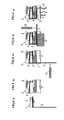
- There are known some types of connectors adapted for use with printed circuit boards wherein a plurality of socket contacts are secured in a housing of each connector. Each of the socket contacts that have not yet been set in place has an elongate unfinished lead continuing from the end of a socket-shaped body. In the prior art method, the unfinished lead is then bent to provide a straight lead extending generally in parallel with the socket-shaped body. An end portion of the straight lead will subsequently be bent again to form a connectable leg protruding down from the housing of a socket connector assembled this way. Figs. 4(a) to 4(e) as whole illustrate such a prior art method of assembling the connector.
- In detail, Fig. 4(a) shows the socket contact 1 referred to above and made by punching and pressing a thin sheet of a metal such as phosphor bronze. Its socket-
shaped body 2 is of a shape to receive a pin contact ( not shown ). The elongateunfinished lead 3 extends downward from the rear end of a bottom of the socket-shaped body 2. - Fig. 4(b) shows a connector housing 5 made of an insulating material such as a Nylon ( registered trademark ) so as to accommodate a plurality of such socket contacts 1.
Compartments 6 formed side by side and in a row will respectively hold therein thesocket bodies 2 of those contacts. Groove-shaped cutouts 7 for receiving the elongateunfinished leads 3 are located in a bottom of the housing 5, correspond to therespective compartments 6. Each cutout 7 extends from the rear end to a front end of the housing 5. Thereference numeral 8 denotes a lockable arm engageable with a mating connector. - Figs. 4(c) to 4(e) show the sequential steps of incorporating the socket contacts 1 into the connector housing 5. The socket-
shaped body 2 of each contact 1 will at first be put in thecompartment 6, from rear of the housing. Then, theunfinished lead 3 extending from eachbody 2 thus fixed in said compartment will be bent using atool 21 so as to have a major portion fitting in the groove-shaped cutout 7. This bent major portion of eachunfinished lead 3 lies straight along a bottom of said cutout 7, substantially in parallel with thebody 2. Such a major portion protruding forward from the front of housing 5 is referred to herein as a -- straight lead 3' --. Subsequently, a rear part of this straight lead 3' fitting in the cutout 7 will be held in place with ananvil 22 as shown in Fig. 4(d) so that afurther tool 23 may press down a frontal part of said lead 3' to form a leg 4 connectable to a printed circuit board ( see Fig. 4(e) ). - Since there is no element or member disposed below and supporting each straight lead 3', those socket contacts 1 set in the housing 5 by the prior art method are not necessarily held firmly enough to be immovable relative thereto. In particular, those straight leads 3' and their connectable legs 4 are susceptible to deformation caused by external force. Thus, it has been considerably difficult to firmly retain the legs 4 on any printed circuit board. Further, presence of a large number of groove-shaped cutouts 7 between the frontal and rear bottom ends of the housing 5 has often caused it to become distorted when molded.
- The present invention was made to diminish these problems in the prior art. Therefore, it is an object of the present invention to provide a novel method of setting contacts in a housing as well as the contacts and the housing themselves that are advantageously employable in the present method, such that the housing can firmly retain each contact's straight lead, whether unfinished or finished, and in use the finished lead can reliably be fixed on a printed circuit board. Another object is to protect the housing from distortion that has been likely to take place when molding same.
- In order to achieve all of these objects at once, a connector housing prepared beforehand for use in the method of the present invention has compartments for receiving socket-shaped bodies of socket contacts, and further has slots penetrating the housing fore and aft and extending generally in parallel with the compartments. Each of the socket contacts also prepared prior to use in the present method has the socket-shaped body and an elongate unfinished lead continuing from the end of said body, and this unfinished lead is processed to form a bent portion adjacent to the socket-shaped body as well as a straight lead continuing from said bent portion and lying generally in parallel with said body. In the present method, the socket-shaped body of each socket contact will be inserted in one of the compartments, accompanied by simultaneous insertion of the straight lead into one of the slots corresponding to the one compartment. Subsequent to this step, an exposed end portion of the straight lead will be bent to form a connectable leg protruding downward from the housing.
- This method and system are advantageous in that the contacts' straight leads are more firmly secured in the respective elongate slots. Any groove-shaped cutouts are no longer necessary in the housing's bottom region, thus avoiding the serious problem of distortion in the molded housings.
-
- Figs. 1(a) to 1(e) illustrate as a whole a process of incorporating socket contacts into a connector housing, according to the method proposed herein, wherein:
- Fig. 1(a) is a vertical cross section of one socket contact comprising a socket-shaped body and an unfinished lead continuing therefrom;
- Fig. 1(b) also is a vertical cross section of the socket contact whose unfinished lead has been bent to form a straight lead;
- Fig. 1(c) similarly is a vertical cross section of a connector housing comprising compartments and slots;
- Fig. 1(d) is a cross section showing the step of inserting the socket-shaped body as well as the straight lead of each contact respectively into one of the compartments and into one slot corresponding thereto, before bending down an exposed end of said straight lead;
- Fig. 1(e) is a vertical cross section of the connector thus finished;
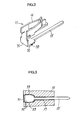
- Fig. 2 is a perspective view of the contact prepared beforehand for use in the present method;
- Fig. 3 is a horizontal cross section of relevant members wherein the unfinished lead penetrates the housing;
- Figs. 4(a) to 4(e) illustrate as a whole a process of incorporating socket contacts into a connector housing, according to one of the prior art methods, wherein:
- Fig. 4(a) is a side-elevational cross section of one socket contact comprising a socket-shaped body and an unfinished lead continuing therefrom;
- Fig. 4(b) is a side-elevational cross section of a connector housing comprising compartments and groove-shaped cutouts;
- Fig. 4(c) shows the first step of placing each contact in the housing and bending the unfinished lead to form a straight lead;
- Fig. 4(d) shows the subsequent step of further bending the straight lead; and
- Fig. 4(e) is a vertical cross section of the connector thus finished.
-
- Fig. 1(a) shows a socket contact 11 for use in the method of the present invention. This contact made by pressing a thin conductive metal sheet such as a phosphor bronze sheet has a socket-
shaped body 12. An elongateunfinished lead 13 continues, like the prior art contact shown in Fig. 4(a), from the rear end of the body's bottom. However, theunfinished lead 13 is already bent before use in the present method so as to provide abent portion 31 and a straight lead 13' continuing therefrom as seen in Fig. 1(b). Fig. 2 shows that the previously processed contact 11 has thebent portion 31 continuing to abasal end portion 32 of the straight lead 13', with both the portions being rendered wider than the remainder portion of said lead.Pawls 33 protrude from lateral edges of thebasal end portion 32 so that they may be hooked in ahousing 15 that will be detailed below. - Fig. 1(c) shows a
connector housing 15 for receiving a plurality of the socket contacts 11. Similarly to the prior art housing shown in Fig. 4(b), thishousing 15 also made of an insulating material such as a Nylon ( registered trademark ) hascompartments 16 formed therein and arranged side by side to respectively receive the contacts' socket-shaped bodies 12. However, flat andelongate slots 17 penetrating thehousing 15 substantially in parallel with thecompartments 16 do substitute for the prior art groove-shaped cutouts 7. The straight lead 13' formed from eachunfinished lead 13 will fits tightly in each ofsuch slots 17. An inlet region of theslot 17 is rendered broader than the remainder regions thereof so as to match the widerbasal end portion 32 of each straight lead 13'. - In assembling the connector, those socket-
shaped bodies 12 already prepared beforehand will be put in thecompartments 16 of the housing, from its rear side, so that the straight leads 13' fit in and through the slots 17 ( see Fig. 1(d) ). Thepawls 33 of each lead will bite the housing's 15 inner faces defining the inlet region of each slot, thereby fastening the lead therein. Subsequently, atool 23 will be used to bend free end portions of leads 13' protruding beyond the front of thehousing 15. These leads' end portions are thus bent downward to formlegs 14 ready for connection to a printed circuit board ( see Fig. 1(e) ). It is not required herein to use anyanvil 22 or the like prior art auxiliary tool shown in Fig. 4(d), because the straight leads 13' tightly fitting in theslots 17 are held immovably relative to thehousing 15. - Thus, the socket contacts 11 whose straight leads 13' are fixed in the
slots 17 of thehousing 15 are kept stable therein, whereby theirlegs 14 can now be connected more firmly to a printed circuit board. - In summary, the method proposed herein is advantageous in that the contacts, particularly their leads, are very strongly held in the housing and more reliably connected to any printed circuit board. The housing free of any groove-shaped cutouts extending over its full width is now free from the problem of distortion that has been inherent in the prior art housings.
Claims (3)
- A method of setting contacts in a connector housing wherein the contacts are socket contacts, the method characterized in that it comprises the steps of: preparing the connector housing (15) having compartments (16) for receiving socket-shaped bodies (12) of the socket contacts (11), and further having slots (17) penetrating the housing fore and aft and extending in parallel with the compartments; further preparing the socket contacts (11) each having an elongate unfinished lead (13) continuing from an end of the socket-shaped body (12) and having a bent portion (31) adjacent thereto as well as a straight lead (13) that continues from the bent portion and lies in parallel with the socket-shaped body; then inserting the socket-shaped body (12) of each socket contact in one of the compartments (16) so that the straight lead (13) is simultaneously inserted into one of the slots (17) corresponding to the one compartment, whereby an end portion of the straight lead protrudes out of the housing so as to be exposed; and subsequently bending the exposed end portion of the straight lead (13) to form a connectable leg (14) protruding downward from the housing.
- A connector housing (15) for use in the method as defined in claim 1, characterized in that the connector housing has the compartments (16) for receiving the socket-shaped bodies of the socket contacts, and further has the slots (17) extending in parallel with the compartments and being flat to closely fit on the straight leads.
- A socket contact (11) for use in the method as defined in claim 1, wherein the socket contact has the elongate unfinished lead (13) continuing from the end of the socket-shaped body and also has the bent portion (31) adjacent thereto as well as the straight lead (13') continuing from the bent portion and lying in parallel with the socket-shaped body, and wherein a basal end portion (32) of the straight lead is wider than the remainder thereof and has pawls (33) protruding from opposite side of the basal end portion.
Applications Claiming Priority (2)
| Application Number | Priority Date | Filing Date | Title |
|---|---|---|---|
| JP272194/97 | 1997-09-17 | ||
| JP9272194A JPH1197149A (en) | 1997-09-17 | 1997-09-17 | Contact assembly method in connector housing |
Publications (2)
| Publication Number | Publication Date |
|---|---|
| EP0903817A1 true EP0903817A1 (en) | 1999-03-24 |
| EP0903817B1 EP0903817B1 (en) | 2006-04-05 |
Family
ID=17510406
Family Applications (1)
| Application Number | Title | Priority Date | Filing Date |
|---|---|---|---|
| EP98307482A Expired - Lifetime EP0903817B1 (en) | 1997-09-17 | 1998-09-15 | Method of setting contacts in a connector housing |
Country Status (4)
| Country | Link |
|---|---|
| US (1) | US6017224A (en) |
| EP (1) | EP0903817B1 (en) |
| JP (1) | JPH1197149A (en) |
| DE (1) | DE69834082T2 (en) |
Cited By (1)
| Publication number | Priority date | Publication date | Assignee | Title |
|---|---|---|---|---|
| EP1220366A2 (en) * | 2000-12-25 | 2002-07-03 | Sumitomo Wiring Systems, Ltd. | Apparatus and method for processing a stacked-type connector of a wire harness |
Families Citing this family (3)
| Publication number | Priority date | Publication date | Assignee | Title |
|---|---|---|---|---|
| US4754950A (en) * | 1984-10-30 | 1988-07-05 | Kabushiki Kaisha Toshiba | Valve |
| JP3638840B2 (en) * | 1999-12-02 | 2005-04-13 | 矢崎総業株式会社 | Connector connection method |
| EP2779328B1 (en) | 2012-04-20 | 2017-03-08 | Schleuniger Holding AG | Method and device for producing a connector |
Citations (5)
| Publication number | Priority date | Publication date | Assignee | Title |
|---|---|---|---|---|
| US3205471A (en) * | 1962-12-05 | 1965-09-07 | Adolf L Herrmann | Electrical connector for a pair of circuit boards |
| EP0009867A1 (en) * | 1978-09-08 | 1980-04-16 | AMP INCORPORATED (a New Jersey corporation) | An electrical plug receptacle connector and a method of manufacturing such a connector |
| EP0218435A2 (en) * | 1985-09-30 | 1987-04-15 | E.I. Du Pont De Nemours And Company | Multi-contact electrical connector and method of assembling same |
| EP0411888A2 (en) * | 1989-08-01 | 1991-02-06 | Molex Incorporated | Electrical connector |
| DE29511998U1 (en) * | 1995-07-25 | 1995-12-21 | Siemens Ag | Plug contact with contact springs |
Family Cites Families (11)
| Publication number | Priority date | Publication date | Assignee | Title |
|---|---|---|---|---|
| US2860318A (en) * | 1956-03-26 | 1958-11-11 | Mallory & Co Inc P R | Socket structure |
| NL137271B (en) * | 1968-08-22 | 1900-01-01 | ||
| US3697933A (en) * | 1971-04-05 | 1972-10-10 | Berg Electronics Inc | Connector block |
| US3993382A (en) * | 1971-12-10 | 1976-11-23 | Rockwell International Corporation | Moisture seal for electrical interconnect system |
| BE793445A (en) * | 1972-02-08 | 1973-04-16 | Elco Corp | FEMALE PLUG FOR SQUARE SECTION CONTACT PIN |
| DE2328620C3 (en) * | 1973-06-05 | 1979-11-08 | Cannon Electric Gmbh, 7056 Weinstadt | Multipole contact |
| FR2276130A1 (en) * | 1974-06-24 | 1976-01-23 | Virax Sa | REVERSIBLE AUTOMATIC TIGHTENING CHUCK |
| US4116520A (en) * | 1977-09-06 | 1978-09-26 | Amp Incorporated | Closed entry connector housing |
| US4597625A (en) * | 1984-07-25 | 1986-07-01 | North American Specialties Corporation | Electrical connector |
| US4790773A (en) * | 1986-09-17 | 1988-12-13 | E. I. Du Pont De Nemours And Company | Electrical receptacle |
| US4878849A (en) * | 1988-04-29 | 1989-11-07 | Amphenol Corporation | Electrical connector having multi-position housing |
-
1997
- 1997-09-17 JP JP9272194A patent/JPH1197149A/en active Pending
-
1998
- 1998-09-15 EP EP98307482A patent/EP0903817B1/en not_active Expired - Lifetime
- 1998-09-15 DE DE69834082T patent/DE69834082T2/en not_active Expired - Fee Related
- 1998-09-16 US US09/154,862 patent/US6017224A/en not_active Expired - Fee Related
Patent Citations (5)
| Publication number | Priority date | Publication date | Assignee | Title |
|---|---|---|---|---|
| US3205471A (en) * | 1962-12-05 | 1965-09-07 | Adolf L Herrmann | Electrical connector for a pair of circuit boards |
| EP0009867A1 (en) * | 1978-09-08 | 1980-04-16 | AMP INCORPORATED (a New Jersey corporation) | An electrical plug receptacle connector and a method of manufacturing such a connector |
| EP0218435A2 (en) * | 1985-09-30 | 1987-04-15 | E.I. Du Pont De Nemours And Company | Multi-contact electrical connector and method of assembling same |
| EP0411888A2 (en) * | 1989-08-01 | 1991-02-06 | Molex Incorporated | Electrical connector |
| DE29511998U1 (en) * | 1995-07-25 | 1995-12-21 | Siemens Ag | Plug contact with contact springs |
Cited By (2)
| Publication number | Priority date | Publication date | Assignee | Title |
|---|---|---|---|---|
| EP1220366A2 (en) * | 2000-12-25 | 2002-07-03 | Sumitomo Wiring Systems, Ltd. | Apparatus and method for processing a stacked-type connector of a wire harness |
| EP1220366A3 (en) * | 2000-12-25 | 2004-01-07 | Sumitomo Wiring Systems, Ltd. | Apparatus and method for processing a stacked-type connector of a wire harness |
Also Published As
| Publication number | Publication date |
|---|---|
| DE69834082T2 (en) | 2006-10-19 |
| EP0903817B1 (en) | 2006-04-05 |
| DE69834082D1 (en) | 2006-05-18 |
| JPH1197149A (en) | 1999-04-09 |
| US6017224A (en) | 2000-01-25 |
Similar Documents
| Publication | Publication Date | Title |
|---|---|---|
| US4904212A (en) | Electrical connector assembly | |
| JP3041676B2 (en) | Electrical connector with improved terminal retention mechanism | |
| EP0846350B1 (en) | Method for making surface mountable connectors | |
| US4050769A (en) | Electrical connector | |
| US7097506B2 (en) | Contact module in which mounting of contacts is simplified | |
| EP1562262B1 (en) | A connector and a method of mounting it to an electric device | |
| JP3078616B2 (en) | Plug connector and manufacturing method thereof | |
| EP1286424A2 (en) | Electrical connector with overmolded and snap locked pieces | |
| US4184735A (en) | Discrete connector | |
| US4708416A (en) | Electrical connecting terminal for a connector | |
| EP0657959B1 (en) | Electrical connector assembly for mounting on a printed circuit board | |
| EP0632549B1 (en) | Electrical connector assembly | |
| US7179123B2 (en) | Terminal and a connector provided with such a terminal | |
| US20040053540A1 (en) | Electrical connector and method of assembling the same | |
| EP0740372A2 (en) | Electrical connector | |
| CN1296314A (en) | Next generation interconnector | |
| KR20050085717A (en) | Flexible cable electrical connector | |
| US6929500B2 (en) | Connector and a method for producing a resin part assembly such as a connector | |
| US6093060A (en) | Electrical connector assembled with a terminal array that is connected by a carrier strip | |
| US5639249A (en) | Printed circuit board connector | |
| US4752246A (en) | Preloaded spring contact electrical terminal | |
| US6017224A (en) | Method of setting contacts in a connector housing | |
| US6899573B2 (en) | Coupled terminal unit and a connector assembling method using the same | |
| WO1997042686A1 (en) | Electrical connector arrangement | |
| EP1061615A1 (en) | Electrical connector and method of assembling same |
Legal Events
| Date | Code | Title | Description |
|---|---|---|---|
| PUAI | Public reference made under article 153(3) epc to a published international application that has entered the european phase |
Free format text: ORIGINAL CODE: 0009012 |
|
| AK | Designated contracting states |
Kind code of ref document: A1 Designated state(s): DE FR GB |
|
| AX | Request for extension of the european patent |
Free format text: AL;LT;LV;MK;RO;SI |
|
| 17P | Request for examination filed |
Effective date: 19990823 |
|
| AKX | Designation fees paid |
Free format text: DE FR GB |
|
| GRAP | Despatch of communication of intention to grant a patent |
Free format text: ORIGINAL CODE: EPIDOSNIGR1 |
|
| GRAS | Grant fee paid |
Free format text: ORIGINAL CODE: EPIDOSNIGR3 |
|
| GRAA | (expected) grant |
Free format text: ORIGINAL CODE: 0009210 |
|
| AK | Designated contracting states |
Kind code of ref document: B1 Designated state(s): DE FR GB |
|
| REG | Reference to a national code |
Ref country code: GB Ref legal event code: FG4D |
|
| RIC1 | Information provided on ipc code assigned before grant |
Ipc: H01R 43/20 20060101ALI20060214BHEP Ipc: H01R 12/20 20060101AFI20060214BHEP |
|
| REF | Corresponds to: |
Ref document number: 69834082 Country of ref document: DE Date of ref document: 20060518 Kind code of ref document: P |
|
| PGFP | Annual fee paid to national office [announced via postgrant information from national office to epo] |
Ref country code: DE Payment date: 20061104 Year of fee payment: 9 |
|
| ET | Fr: translation filed | ||
| PLBE | No opposition filed within time limit |
Free format text: ORIGINAL CODE: 0009261 |
|
| STAA | Information on the status of an ep patent application or granted ep patent |
Free format text: STATUS: NO OPPOSITION FILED WITHIN TIME LIMIT |
|
| 26N | No opposition filed |
Effective date: 20070108 |
|
| PGFP | Annual fee paid to national office [announced via postgrant information from national office to epo] |
Ref country code: GB Payment date: 20070920 Year of fee payment: 10 |
|
| PG25 | Lapsed in a contracting state [announced via postgrant information from national office to epo] |
Ref country code: DE Free format text: LAPSE BECAUSE OF NON-PAYMENT OF DUE FEES Effective date: 20080401 |
|
| REG | Reference to a national code |
Ref country code: FR Ref legal event code: ST Effective date: 20080531 |
|
| PG25 | Lapsed in a contracting state [announced via postgrant information from national office to epo] |
Ref country code: FR Free format text: LAPSE BECAUSE OF NON-PAYMENT OF DUE FEES Effective date: 20071001 |
|
| PG25 | Lapsed in a contracting state [announced via postgrant information from national office to epo] |
Ref country code: FR Free format text: LAPSE BECAUSE OF NON-PAYMENT OF DUE FEES Effective date: 20060930 |
|
| GBPC | Gb: european patent ceased through non-payment of renewal fee |
Effective date: 20080915 |
|
| PG25 | Lapsed in a contracting state [announced via postgrant information from national office to epo] |
Ref country code: GB Free format text: LAPSE BECAUSE OF NON-PAYMENT OF DUE FEES Effective date: 20080915 |