EP0903789A2 - Nonvolatile semiconductor storage apparatus and production method of the same - Google Patents
Nonvolatile semiconductor storage apparatus and production method of the same Download PDFInfo
- Publication number
- EP0903789A2 EP0903789A2 EP98116737A EP98116737A EP0903789A2 EP 0903789 A2 EP0903789 A2 EP 0903789A2 EP 98116737 A EP98116737 A EP 98116737A EP 98116737 A EP98116737 A EP 98116737A EP 0903789 A2 EP0903789 A2 EP 0903789A2
- Authority
- EP
- European Patent Office
- Prior art keywords
- conductive type
- well
- control gate
- storage apparatus
- charge
- Prior art date
- Legal status (The legal status is an assumption and is not a legal conclusion. Google has not performed a legal analysis and makes no representation as to the accuracy of the status listed.)
- Withdrawn
Links
- 239000004065 semiconductor Substances 0.000 title claims abstract description 102
- 238000003860 storage Methods 0.000 title claims abstract description 37
- 238000004519 manufacturing process Methods 0.000 title claims description 9
- 239000000758 substrate Substances 0.000 claims abstract description 39
- 238000005530 etching Methods 0.000 claims abstract description 36
- 238000000034 method Methods 0.000 claims description 8
- 238000005520 cutting process Methods 0.000 claims description 3
- 238000009413 insulation Methods 0.000 abstract description 22
- 238000009792 diffusion process Methods 0.000 abstract description 21
- 239000002131 composite material Substances 0.000 abstract description 8
- 238000005468 ion implantation Methods 0.000 abstract description 3
- 239000010410 layer Substances 0.000 description 64
- 239000010408 film Substances 0.000 description 16
- 239000002184 metal Substances 0.000 description 14
- 230000006870 function Effects 0.000 description 6
- 239000011229 interlayer Substances 0.000 description 6
- 230000006378 damage Effects 0.000 description 4
- 239000013039 cover film Substances 0.000 description 3
- 238000005516 engineering process Methods 0.000 description 1
Images


Classifications
-
- H—ELECTRICITY
- H10—SEMICONDUCTOR DEVICES; ELECTRIC SOLID-STATE DEVICES NOT OTHERWISE PROVIDED FOR
- H10B—ELECTRONIC MEMORY DEVICES
- H10B41/00—Electrically erasable-and-programmable ROM [EEPROM] devices comprising floating gates
- H10B41/30—Electrically erasable-and-programmable ROM [EEPROM] devices comprising floating gates characterised by the memory core region
-
- H—ELECTRICITY
- H10—SEMICONDUCTOR DEVICES; ELECTRIC SOLID-STATE DEVICES NOT OTHERWISE PROVIDED FOR
- H10B—ELECTRONIC MEMORY DEVICES
- H10B69/00—Erasable-and-programmable ROM [EPROM] devices not provided for in groups H10B41/00 - H10B63/00, e.g. ultraviolet erasable-and-programmable ROM [UVEPROM] devices
-
- H—ELECTRICITY
- H10—SEMICONDUCTOR DEVICES; ELECTRIC SOLID-STATE DEVICES NOT OTHERWISE PROVIDED FOR
- H10D—INORGANIC ELECTRIC SEMICONDUCTOR DEVICES
- H10D30/00—Field-effect transistors [FET]
- H10D30/01—Manufacture or treatment
- H10D30/021—Manufacture or treatment of FETs having insulated gates [IGFET]
- H10D30/0411—Manufacture or treatment of FETs having insulated gates [IGFET] of FETs having floating gates
-
- H—ELECTRICITY
- H10—SEMICONDUCTOR DEVICES; ELECTRIC SOLID-STATE DEVICES NOT OTHERWISE PROVIDED FOR
- H10D—INORGANIC ELECTRIC SEMICONDUCTOR DEVICES
- H10D30/00—Field-effect transistors [FET]
- H10D30/60—Insulated-gate field-effect transistors [IGFET]
- H10D30/68—Floating-gate IGFETs
- H10D30/681—Floating-gate IGFETs having only two programming levels
Definitions
- the present invention relates to a nonvolatile semiconductor storage apparatus such as a flash memory having a floating gate and a control gate to which a positive and negative voltages are applied during a memory cell operation.
- Fig. 15 to Fig. 17 schematically show a conventional nonvolatile semiconductor storage apparatus of this type.
- Fig. 17 is a plan view showing the conventional nonvolatile semiconductor storage apparatus.
- Fig. 15 is a cross sectional view along the line A-A' in Fig. 17, and
- Fig. 16 is a cross sectional view along the line B-B' in Fig. 17. Explanation will be given on this conventional nonvolatile semiconductor storage apparatus with reference to these drawings.
- a P-type semiconductor substrate 1 there is formed an N-type well 2 to oppose to the P-type semiconductor substrate 1.
- N-type well 2 there is formed a P-type well 3 to oppose to the N-type well 2.
- the P-type well 3 has a main surface on which a composite gate 8 is formed.
- the composite gate 8 consists of a first gate insulation film 4, a floating gate 5, a second gate insulation film 6, and a control gate 7 which are successively layered.
- a source 10 and a drain 11 are formed by an N + -diffused layer.
- a first inter-layer insulation film 12 and a contact 13 over which a first metal wiring 14, a second inter-layer insulation film 15, a second metal wiring 16, and a cover film 17 are formed.
- the conventional technology has a problem that a charge-up during wiring layer etching causes a memory cell floating gate to trap an electron or hole, causing characteristic fluctuation and an insulation film reliability lowering or insulation destruction. This is because both of positive and negative voltages are applied to the control gate during a memory cell operation and the control gate cannot be connected to a charge-up preventing diode. That is, if a charge-up preventing diode is connected to the control gate, the charge-up preventing diode is biased in a forward direction by either positive or negative voltage applied and accordingly, it becomes impossible to apply a desired voltage to the control gate.
- the nonvolatile semiconductor storage apparatus is an improved nonvolatile semiconductor storage apparatus having a floating gate and a control gate on a semiconductor substrate.
- the nonvolatile semiconductor storage apparatus is characterized in that a first well of a second conductive type opposite to the first conductive type of the semiconductor substrate is formed on the semiconductor substrate, and in the first well is formed a semiconductor layer of the first conductive type, which semiconductor layer is electrically connected to the control gate.
- the nonvolatile semiconductor storage apparatus is characterized in that on the semiconductor substrate of a first conductive type is formed a first well of a second conductive type opposite to the first conductive type of the semiconductor substrate, and in the first well is formed a second well of the first conductive type, in which is formed a semiconductor layer of the second conductive type, which semiconductor layer is electrically connected to the control gate. That is , a first well of an opposite conductive type to the semiconductor substrate is formed on the semiconductor substrate. A second well of an opposite conductive type to the first well is formed in the first well, and a semiconductor layer of an opposite conductive type to the second well is formed in the second well. This semiconductor layer is connected to the memory cell control gate so as to realize a charge-up preventing element.
- the nonvolatile semiconductor storage apparatus production method is an improved production method for producing a nonvolatile semiconductor storage apparatus having a floating gate and a control gate on a semiconductor substrate.
- the production method according to a first embodiment is characterized by steps of: forming on the semiconductor substrate of a first conductive type, a semiconductor layer of a second conductive type opposite to the first conductive type; electrically connecting the semiconductor layer to the control gate, and electrically insulating the semiconductor layer from the control gate during or after a wiring layer etching.
- the nonvolatile semiconductor storage apparatus production method is characterized by steps of: forming on the semiconductor substrate of a first conductive type, a semiconductor layer of a second conductive type opposite to the first conductive type; electrically connecting the semiconductor layer to the control gate using a wiring, and cutting off the wiring connecting the semiconductor layer to the control gate during or after a wiring layer etching.
- the memory cell control gate is connected to the charge-up preventing diode and during a final wiring layer etching, the control gate is cut off from the charge-up preventing diode.
- the charge-up preventing element for preventing charge-up during a wiring layer etching assures an electric flow path, enabling to prevent a charge-up which may cause a memory cell characteristic fluctuation and an insulation film reliability lowering or insulation destruction as well as to enable to apply both of positive and negative voltages during a cell operation.
- an N-type well is formed on a P-type substrate.
- a P-type well In the N-type well is formed a P-type well.
- a N + diffusion layer is formed in the P-type well. This N + diffusion layer is connected to the control gate, whereas the P-type substrate and the N-type well are grounded.
- the direction from the P-type well to the N-type well is a forward direction, and because the N-type well is grounded, it is possible to realize a diode having the N + diffusion layer in the P-type well, assuring a current flow path.
- a direction from the N+ diffusion layer to the P-type well is a forward bias, thus enabling to realize a diode having the P-type well in the N-type well, assuring a current flow path.
- the control gate is cut off from the charge-up preventing diode, it is possible to assure a current flow path with the charge-up preventing diode and disconnection of the charge-up preventing diode by etching such as a final wiring layer etching enables to apply both of positive and negative voltages during a memory cell operation.
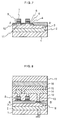
- Fig. 1 to Fig. 3 schematically show a nonvolatile semiconductor storage apparatus according to a first embodiment of the present invention.
- Fig. 1 is a cross sectional view along a line A-A' in Fig. 3
- Fig. 2 is a cross sectional view along a line B-B2 in Fig. 3.
- Fig. 3 is a plan view showing the nonvolatile semiconductor storage apparatus according to the first embodiment.
- a first well 52 of second conductive type which is opposite to the first conductive type is formed.
- a second well 53 of the first conductive type is formed.
- a composite gate 8 is formed by a first gate insulation film 4, a floating gate 5, a second gate insulation film 6, and a control gate 7 which are successively layered.
- a source 10, a drain 11, and a charge-up preventing element diffusion layer 18 of the second conductive type are formed by ion implantation.
- first inter-layer insulation film 12 and a contact 13 are partially covered by a fist metal wiring 14, a second inter-layer insulation film 15, a second metal wiring 16, and a cover film 17, thus constituting a nonvolatile semiconductor storage apparatus.
- control gate 7 is connected to the charge-up preventing element diffusion layer 18 by the first metal wiring 14.
- the first metal wiring 14 is connected to the second metal wiring 16.
- the semiconductor substrate 51 and the first well 52 are grounded.
- Fig. 4 to Fig. 6 schematically shows a wiring layer etching process according to this embodiment.
- Fig. 4 is a cross sectional view along a line A-A' in Fig. 6, and
- Fig. 5 is a cross sectional view along a line B-B' in Fig. 6.
- Fig. 6 is a plan view.
- explanation will be given on the function of the present embodiment with reference to these embodiments.
- the semiconductor substrate 51 and the second well 53 are of the first conductive type, whereas the first well 52 and the charge-up preventing element diffusion layer 18 are of the second conductive type.
- the semiconductor substrate 51 and the fist well 52 are grounded. Accordingly, when a forward direction voltage is applied from the diffusion layer 18 to the second well 53 at a charge-up during the wiring layer etching, the second well 53 and the first well 52 function as a charge-up preventing diode (Fig. 4).
- a reverse direction voltage is caused by charge-up from the diffusion layer 18 to the second well 53, a forward direction current flows from the second well 53 to the first well 52 and accordingly, the diffusion layer 18 and the second well 53 function as a charge-up preventing diode (Fig. 5.).
- Fig. 7 to Fig. 9 schematically show a specific example of the present embodiment.
- Fig. 7 is a cross sectional view along a line A-A' in Fig. 9
- Fig. 8 is a cross sectional view along a line B-B' in Fig. 9.
- Fig. 9 is a plan view.
- an N-type well 2 of the opposite conductive type to the P-type semiconductor substrate 1 is formed.
- a P-type well 3 is formed to oppose to the N-type conductivity.
- a composite gate 8 consisting of: a first gate insulation film 4 having a thickness in the order of 100 Angstrom, a floating gate 5 having a thickness in the order of 1000 Angstrom, a second gate insulation film 6 having a thickness of 150 Angstrom, and a control gate 7 having a thickness in the order of 2000 Angstrom which are successively layered.
- a source 10, a drain 11, and a charge-up preventing element diffusion layer 18 are formed by way of ion implantation. These are partially covered by a first inter-layer insulation film 12 having a thickness in the order of 7000 Angstrom and a contact 13, on which are further formed successively a first metal wiring 14 having a thickness in the order of 5000 angstrom, a second inter-layer insulation film 15 having a thickness in the order of 6000 Angstrom, a second metal wiring 16 having a thickness in the order of 7000 Angstrom, and a cover film 17 having a thickness in the order of 9000 Angstrom, thus forming a flash memory.
- control gate 7 is connected to the charge-up preventing element diffusion layer 18 by the first metal wiring 14.
- the first metal wiring 14 is connected to the second metal wiring 16.
- the P-type semiconductor substrate 1 and the N-type well 2 are grounded.
- Fig. 10 to Fig. 12 schematically show a wiring layer etching process in the present embodiment.
- Fig. 10 is a cross sectional view along a line A-A' in Fig. 12
- Fig. 11 is a cross sectional view along a line B-B7 in Fig. 12.
- Fig. 12 is a plan view.
- the P-type semiconductor substrate 1 and the P-type well 3 are of an identical conductive type, whereas the N-type well 2 and the charge-up preventing element diffusion layer 18 are of another identical conductive type.
- the semiconductor substrate 1 and the N-type well 2 are grounded. Accordingly, when a forward direction voltage is applied from the diffusion layer 18 to the P-type well 3 at a charge-up during the wiring layer etching, the P-type well 3 and the N-type well 2 function as a charge-up preventing diode (Fig. 10).
- Fig. 13 and Fig. 14 schematically show a nonvolatile semiconductor storage apparatus according to a second embodiment of the present invention.
- Fig. 13 is a cross sectional view along a line B-B' in Fig. 14.
- Fig. 14 is a plan view.
- Like components as in the first embodiment (Fig. 1 to Fig. 3) are denoted by like symbols and their explanations will be omitted.
- a charge-up preventing diode used when only positive or negative voltage is applied to the control gate 7 during a memory cell operation, and a current path is assured to prevent a charge-up.
- the control gate 7 is cut off from the charge-up preventing diode in a memory cell. This enables to apply both of positive and negative voltages during a memory cell operation as well as to prevent charge-up during a wiring layer etching.
- the aforementioned cut-off of the control gate 7 from the charge-up preventing diode in a memory cell may be carried out other than in the final wiring layer etching step such as in a cut-off dedicated etching process.
- the present invention enables to prevent trap of electron or hole in a memory cell floating gate due to charge-up during a wiring layer etching. This enables to prevent memory cell characteristic fluctuation and insulation film reliability lowering or insulation destruction.
- a charge-up preventing element is provided so that no operation trouble is caused even if both positive and negative voltages are applied to the memory cell control gate.
- This charge-up preventing element is connected to the control gate or a charge-up preventing diode is connected to the control gate through a wiring layer, which are later cut-off from each other during an etching such as in the final wiring layer etching.
- etching such as in the final wiring layer etching.
Landscapes
- Non-Volatile Memory (AREA)
- Semiconductor Memories (AREA)
Abstract
Description
Claims (9)
- A nonvolatile semiconductor storage apparatus having a floating gate and a control gate on a semiconductor substrate of a first conductive type,
wherein a first well of a second conductive type opposite to said first conductive type of said semiconductor substrate is formed on said semiconductor substrate, and in said first well is formed a semiconductor layer of said first conductive type, which semiconductor layer is electrically connected to said control gate. - A nonvolatile semiconductor storage apparatus having a floating gate and a control gate on a semiconductor substrate of a first conductive type,
wherein a first well of a second conductive type opposite to said first conductive type of said semiconductor substrate is formed on said semiconductor substrate, and in said first well is formed a second well of said first conductive type, in which second well is formed a semiconductor layer of said second conductive type, said semiconductor layer being electrically connected to said control gate. - A nonvolatile semiconductor storage apparatus as claimed in Claim 2, wherein said semiconductor substrate and said first well are grounded and said second well is floating or grounded.
- A method for producing a nonvolatile semiconductor storage apparatus having a floating gate and a control gate on a semiconductor substrate, said method comprising steps of:forming on said semiconductor substrate of a first conductive type, a semiconductor layer of a second conductive type opposite to the first conductive typeelectrically connecting said semiconductor layer to said control gate, andelectrically insulating said semiconductor layer from said control gate during a wiring layer etching.
- A method for producing a nonvolatile semiconductor storage apparatus having a floating gate and a control gate on a semiconductor substrate of, said method comprising steps of:forming on said semiconductor substrate of a first conductive type, a semiconductor layer of a second conductive type opposite to the first conductive typeelectrically connecting said semiconductor layer to said control gate, andelectrically insulating said semiconductor layer from said control gate after a wiring layer etching.
- A method for producing a nonvolatile semiconductor storage apparatus having a floating gate and a control gate on a semiconductor substrate of, said method comprising steps of:forming on said semiconductor substrate of a first conductive type, a semiconductor layer of a second conductive type opposite to the first conductive typeelectrically connecting said semiconductor layer to said control gate using a wiring, andcutting off said wiring connecting said semiconductor layer to said control gate during a wiring layer etching.
- A method for producing a nonvolatile semiconductor storage apparatus having a floating gate and a control gate on a semiconductor substrate of, said method comprising steps of:forming on said semiconductor substrate of a first conductive type, a semiconductor layer of a second conductive type opposite to the first conductive typeelectrically connecting said semiconductor layer to said control gate using a wiring, andcutting off said wiring connecting said semiconductor layer to said control gate after a wiring layer etching.
- An apparatus as claimed in Claim 1, 2 or 3, wherein said nonvolatile semiconductor storage apparatus is a flash memory.
- A method as claimed in Claim 4, 5, 6 or 7, wherein said nonvolatile semiconductor storage apparatus is a flash memory.
Applications Claiming Priority (3)
| Application Number | Priority Date | Filing Date | Title |
|---|---|---|---|
| JP25569797 | 1997-09-19 | ||
| JP25569797A JP3221369B2 (en) | 1997-09-19 | 1997-09-19 | Nonvolatile semiconductor memory device and method of manufacturing the same |
| JP255697/97 | 1997-09-19 |
Publications (2)
| Publication Number | Publication Date |
|---|---|
| EP0903789A2 true EP0903789A2 (en) | 1999-03-24 |
| EP0903789A3 EP0903789A3 (en) | 1999-12-08 |
Family
ID=17282390
Family Applications (1)
| Application Number | Title | Priority Date | Filing Date |
|---|---|---|---|
| EP98116737A Withdrawn EP0903789A3 (en) | 1997-09-19 | 1998-09-03 | Nonvolatile semiconductor storage apparatus and production method of the same |
Country Status (5)
| Country | Link |
|---|---|
| US (2) | US6392268B2 (en) |
| EP (1) | EP0903789A3 (en) |
| JP (1) | JP3221369B2 (en) |
| KR (1) | KR100372392B1 (en) |
| CN (1) | CN1130774C (en) |
Families Citing this family (9)
| Publication number | Priority date | Publication date | Assignee | Title |
|---|---|---|---|---|
| KR100363841B1 (en) * | 1999-12-28 | 2002-12-06 | 주식회사 하이닉스반도체 | Flash memory device |
| US6620673B1 (en) * | 2002-03-08 | 2003-09-16 | Alpine Microsystems, Inc. | Thin film capacitor having multi-layer dielectric film including silicon dioxide and tantalum pentoxide |
| JP2006024598A (en) * | 2004-07-06 | 2006-01-26 | Fujitsu Ltd | Manufacturing method of semiconductor device |
| WO2006129342A1 (en) * | 2005-05-30 | 2006-12-07 | Spansion Llc | Semiconductor device and method for manufacturing same |
| KR100857741B1 (en) | 2006-10-02 | 2008-09-10 | 삼성전자주식회사 | Nonvolatile Memory Device and Manufacturing Method |
| US20090179247A1 (en) * | 2008-01-16 | 2009-07-16 | Renesas Technology Corp. | Semiconductor device |
| JP5259246B2 (en) | 2008-05-09 | 2013-08-07 | ルネサスエレクトロニクス株式会社 | Semiconductor device |
| JP2011176163A (en) | 2010-02-25 | 2011-09-08 | Panasonic Corp | Nonvolatile semiconductor storage device |
| US8816438B2 (en) * | 2012-12-14 | 2014-08-26 | Spansion Llc | Process charging protection for split gate charge trapping flash |
Family Cites Families (18)
| Publication number | Priority date | Publication date | Assignee | Title |
|---|---|---|---|---|
| JPS57100768A (en) * | 1980-12-16 | 1982-06-23 | Nec Corp | Manufacture of field effect semiconductor device |
| JPH0724261B2 (en) * | 1989-01-20 | 1995-03-15 | 株式会社東芝 | Method for manufacturing semiconductor device |
| JPH02297960A (en) * | 1989-05-12 | 1990-12-10 | Nippon Telegr & Teleph Corp <Ntt> | Semiconductor device and manufacture thereof |
| JP3068291B2 (en) | 1990-12-12 | 2000-07-24 | 新日本製鐵株式会社 | Semiconductor storage device |
| DE69312676T2 (en) | 1993-02-17 | 1997-12-04 | Sgs Thomson Microelectronics | Process for the production of integrated components including non-volatile memory and transistors with tunnel oxide protection |
| JPH07244991A (en) * | 1994-03-01 | 1995-09-19 | Sony Corp | Floating gate type nonvolatile semiconductor memory device |
| US5457652A (en) * | 1994-04-01 | 1995-10-10 | National Semiconductor Corporation | Low voltage EEPROM |
| US5424233A (en) * | 1994-05-06 | 1995-06-13 | United Microflectronics Corporation | Method of making electrically programmable and erasable memory device with a depression |
| KR100372905B1 (en) * | 1994-09-13 | 2003-05-01 | 애질런트 테크놀로지스, 인크. | A device and method of manufacture for frotection against plasma charging damage in advanced mos technologies |
| JP3380836B2 (en) * | 1995-07-04 | 2003-02-24 | 松下電器産業株式会社 | MIS semiconductor device and method of manufacturing the same |
| US5903031A (en) * | 1995-07-04 | 1999-05-11 | Matsushita Electric Industrial Co., Ltd. | MIS device, method of manufacturing the same, and method of diagnosing the same |
| JP3183326B2 (en) * | 1996-07-17 | 2001-07-09 | 日本電気株式会社 | Read-only semiconductor memory device |
| US5998826A (en) * | 1996-09-05 | 1999-12-07 | Macronix International Co., Ltd. | Triple well floating gate memory and operating method with isolated channel program, preprogram and erase processes |
| JP2924832B2 (en) * | 1996-11-28 | 1999-07-26 | 日本電気株式会社 | Method for manufacturing semiconductor device |
| JPH10173157A (en) * | 1996-12-06 | 1998-06-26 | Toshiba Corp | Semiconductor device |
| JPH10200077A (en) | 1997-01-08 | 1998-07-31 | Sony Corp | Semiconductor device and manufacturing method thereof |
| KR100239424B1 (en) * | 1997-09-26 | 2000-01-15 | 김영환 | Static electricity protection circuit |
| US6060742A (en) * | 1999-06-16 | 2000-05-09 | Worldwide Semiconductor Manufacturing Corporation | ETOX cell having bipolar electron injection for substrate-hot-electron program |
-
1997
- 1997-09-19 JP JP25569797A patent/JP3221369B2/en not_active Expired - Fee Related
-
1998
- 1998-09-03 EP EP98116737A patent/EP0903789A3/en not_active Withdrawn
- 1998-09-04 KR KR10-1998-0036502A patent/KR100372392B1/en not_active Expired - Fee Related
- 1998-09-17 US US09/154,982 patent/US6392268B2/en not_active Expired - Fee Related
- 1998-09-18 CN CN98119837A patent/CN1130774C/en not_active Expired - Fee Related
-
2001
- 2001-08-17 US US09/930,950 patent/US6503797B2/en not_active Expired - Fee Related
Also Published As
| Publication number | Publication date |
|---|---|
| CN1212466A (en) | 1999-03-31 |
| KR100372392B1 (en) | 2003-04-21 |
| JP3221369B2 (en) | 2001-10-22 |
| US20010055847A1 (en) | 2001-12-27 |
| CN1130774C (en) | 2003-12-10 |
| US20010052616A1 (en) | 2001-12-20 |
| EP0903789A3 (en) | 1999-12-08 |
| US6503797B2 (en) | 2003-01-07 |
| KR19990029546A (en) | 1999-04-26 |
| US6392268B2 (en) | 2002-05-21 |
| JPH1197560A (en) | 1999-04-09 |
Similar Documents
| Publication | Publication Date | Title |
|---|---|---|
| US6232182B1 (en) | Non-volatile semiconductor memory device including memory transistor with a composite gate structure and method of manufacturing the same | |
| EP0186855B1 (en) | Semiconductor read only memory device and method of manufacturing the same | |
| US20070158680A1 (en) | Semiconductor device having IGBT and diode | |
| US6417044B1 (en) | Non-volatile memory and memory of manufacturing the same | |
| US5594688A (en) | Nonvolatile semiconductor memory device and method of producing the same | |
| US6392268B2 (en) | Nonvolatile semiconductor storage apparatus and production method of the same | |
| JP2003203999A (en) | Nonvolatile semiconductor memory device and method of manufacturing the same | |
| KR100306733B1 (en) | Semiconductor device and method of fabricating the same | |
| US6696732B2 (en) | Semiconductor device having S/D to S/D connection and isolation region between two semiconductor elements | |
| FR2693308A1 (en) | Triple grid eeprom memory and its manufacturing process. | |
| US5751036A (en) | Floating gate type non-volatile semiconductor memory device | |
| KR100328598B1 (en) | semiconductor device having junction diode and method for fabricating the same | |
| JP2819975B2 (en) | Nonvolatile semiconductor memory device and method of manufacturing the same | |
| JP3049001B2 (en) | FUSE DEVICE AND ITS MANUFACTURING METHOD | |
| EP0432792B1 (en) | Nonvolatile semiconductor memory device and method of manufacturing the same | |
| US20080096328A1 (en) | Nonvolatile memory devices and methods of forming the same | |
| US7061112B2 (en) | Semiconductor device including an electrical contact connected to an interconnection | |
| JPH05110113A (en) | Semiconductor memory device and storage information reading method thereof | |
| KR100789409B1 (en) | Ypyrom element and its manufacturing method | |
| KR100294775B1 (en) | Semiconductor device and manufacturing method thereof | |
| EP0112078A2 (en) | A semiconductor memory element and a method for manufacturing it | |
| US20010006234A1 (en) | Semiconductor device and method of manufacturing the same | |
| US20030109117A1 (en) | Semiconductor device and manufacturing method thereof | |
| JPH1022404A (en) | Method for manufacturing split gate type semiconductor device | |
| JPH0821635B2 (en) | Method for controlling conduction state of MOS transistor and integrated circuit obtained by implementing the method |
Legal Events
| Date | Code | Title | Description |
|---|---|---|---|
| PUAI | Public reference made under article 153(3) epc to a published international application that has entered the european phase |
Free format text: ORIGINAL CODE: 0009012 |
|
| AK | Designated contracting states |
Kind code of ref document: A2 Designated state(s): DE FR GB |
|
| AX | Request for extension of the european patent |
Free format text: AL;LT;LV;MK;RO;SI |
|
| PUAL | Search report despatched |
Free format text: ORIGINAL CODE: 0009013 |
|
| AK | Designated contracting states |
Kind code of ref document: A3 Designated state(s): AT BE CH CY DE DK ES FI FR GB GR IE IT LI LU MC NL PT SE |
|
| AX | Request for extension of the european patent |
Free format text: AL;LT;LV;MK;RO;SI |
|
| 17P | Request for examination filed |
Effective date: 19991027 |
|
| AKX | Designation fees paid |
Free format text: DE FR GB |
|
| RAP1 | Party data changed (applicant data changed or rights of an application transferred) |
Owner name: NEC ELECTRONICS CORPORATION |
|
| STAA | Information on the status of an ep patent application or granted ep patent |
Free format text: STATUS: THE APPLICATION HAS BEEN WITHDRAWN |
|
| 18W | Application withdrawn |
Effective date: 20050812 |