EP0903765B1 - Disjoncteur - Google Patents
Disjoncteur Download PDFInfo
- Publication number
- EP0903765B1 EP0903765B1 EP98307415A EP98307415A EP0903765B1 EP 0903765 B1 EP0903765 B1 EP 0903765B1 EP 98307415 A EP98307415 A EP 98307415A EP 98307415 A EP98307415 A EP 98307415A EP 0903765 B1 EP0903765 B1 EP 0903765B1
- Authority
- EP
- European Patent Office
- Prior art keywords
- circuit breaker
- core
- housing
- output
- primary housing
- Prior art date
- Legal status (The legal status is an assumption and is not a legal conclusion. Google has not performed a legal analysis and makes no representation as to the accuracy of the status listed.)
- Expired - Lifetime
Links
- 239000004020 conductor Substances 0.000 claims abstract description 19
- 125000006850 spacer group Chemical class 0.000 claims description 11
- 239000000956 alloy Substances 0.000 claims description 3
- 229910045601 alloy Inorganic materials 0.000 claims description 3
- 238000004804 winding Methods 0.000 claims description 3
- 239000011810 insulating material Substances 0.000 claims description 2
- 239000000463 material Substances 0.000 claims description 2
- 230000000712 assembly Effects 0.000 description 1
- 238000000429 assembly Methods 0.000 description 1
- 238000010438 heat treatment Methods 0.000 description 1
- 238000009413 insulation Methods 0.000 description 1
Images


Classifications
-
- H—ELECTRICITY
- H01—ELECTRIC ELEMENTS
- H01H—ELECTRIC SWITCHES; RELAYS; SELECTORS; EMERGENCY PROTECTIVE DEVICES
- H01H83/00—Protective switches, e.g. circuit-breaking switches, or protective relays operated by abnormal electrical conditions otherwise than solely by excess current
- H01H83/14—Protective switches, e.g. circuit-breaking switches, or protective relays operated by abnormal electrical conditions otherwise than solely by excess current operated by imbalance of two or more currents or voltages, e.g. for differential protection
- H01H83/144—Protective switches, e.g. circuit-breaking switches, or protective relays operated by abnormal electrical conditions otherwise than solely by excess current operated by imbalance of two or more currents or voltages, e.g. for differential protection with differential transformer
- H01H2083/148—Protective switches, e.g. circuit-breaking switches, or protective relays operated by abnormal electrical conditions otherwise than solely by excess current operated by imbalance of two or more currents or voltages, e.g. for differential protection with differential transformer with primary windings formed of rigid copper conductors
Definitions
- THIS INVENTION relates to a circuit breaker. More particularly, the invention relates to a circuit breaker incorporating an earth leakage facility.
- a circuit breaker which includes
- a circuit breaker according to the preamble of claim 1 is known from FR 2 681 725.
- the primary housing may be dimensioned to be the same size as a housing and with the same size arc chutes of a circuit breaker of the same rating but excluding an earth leakage facility.
- the term "same size” refers to a primary housing of a circuit breaker which has the same dimensions, interior capacity and layout as a housing of a conventional circuit breaker, i.e. a circuit breaker without an earth leakage facility, of the same rating. Corresponding words thus have corresponding means.
- the primary housing may include a base having a floor bounded by a side wall portion, the core lying in a plane extending parallel to the floor.
- the core may be a strip-wound core of a nanocrystalline alloy.
- the core may incorporate shielding material and insulating material and may be dimensioned to be accommodated in a recess in the primary housing.
- each electrically conductive element may be in the form of a spacer of an electrically conductive material, the spacers projecting from the conductors through the opening of the core to be surrounded by the core.
- An output lug, of an electrically conductive material, may be mounted on each spacer.
- Each output conductor may be fastened to its associated spacer and output lug by a fastening means.
- the current sensing circuitry may include a current sensing means.
- the current sensing means may comprise a current transformer having a winding surrounding the output lugs.
- the current transformer and the earth leakage core may be connected to their appropriate circuitry which is contained in the secondary housing.
- the secondary housing may form a unit which is removably received in the primary housing of the circuit breaker.
- the unit may incorporate a tripping device which acts on the operating handle of the circuit breaker.
- the invention extends also to a circuit breaker which includes
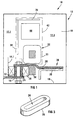
- the circuit breaker 10 comprises a primary housing 12, the base of which is illustrated in the drawings.
- the housing 12 is the same size as a housing of a circuit breaker of the same rating but excluding an earth leakage facility.
- An operating mechanism 14 ( Figure 5) and handle arrangement (not shown) of conventional size and rating are mounted via a frame in the housing 12, an edge of the frame being indicated schematically at 14.1 in Figure 1 of the drawings.
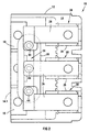
- the housing 12 is effectively divided into three parts, the operating mechanism 14 being contained within a central part 12.1 of the housing 12, an arc chute arrangement 15 being arranged in a part 12.2 on one side of the operating mechanism 14 with output conductors 16 of the operating mechanism 14 extending into a further part 12.3 on an opposed side of the operating mechanism 14.
- the base of the housing 12 has a floor 18 ( Figure 4) surrounded by a side wall 19.
- the circuit breaker 10 includes an earth leakage facility having an oval-shaped core 20 illustrated in Figure 3 of the drawings.
- the core 20 is a strip-wound core of a nanocrystalline alloy called VITROPERM 800F (Vitroperm 800F is a registered trade mark of Vacuumschmelze GmbH of Hanau, Germany).
- VITROPERM 800F is a registered trade mark of Vacuumschmelze GmbH of Hanau, Germany.
- the core 20 lies in a plane parallel to the floor 18 of the base of the housing 12 in the part 12.3 of the housing 12.
- An electrical spacer 22 ( Figure 1) is mounted on each output conductor 16 to protrude through an opening 24 in the core 20.
- Each spacer 22 has an output lug 26 mounted thereon, the output lugs 26 being of an electrically conductive material.
- Each output lug 26 is aligned with an output element 28 to form an output terminal 30 of the circuit breaker 10, each terminal 30 being accommodated in the part 12.3 of the housing 12.
- Each conductor 16, spacer 22 and output lug 26 are fastened together by a bolt and nut combination 44 to hold the assemblies so formed together.
- the circuit breaker 10 includes a current sensing means 32 for sensing current through the output terminals 30 of the circuit breaker 10.
- the current sensing means 32 includes a current transformer 33 having a winding 34 extending about the output lugs 26.
- An output from the current transformer 33 is connected to current sensing circuitry illustrated schematically in Figure 1 by a printed circuit board 36.
- an output from the core 20 of the earth leakage facility is connected to earth leakage sensing circuitry indicated schematically in Figure 1 by a printed circuit board 38.
- the current sensing circuitry 36 and the earth leakage sensing circuitry 38 are both connected to a low energy shunt trip 40 which, in a conventional fashion, operates a tripping mechanism (not shown), the tripping mechanism, in turn, being connected to the operating handle of the operating mechanism 14 of the circuit breaker 10.
- the current transformer 33, the current sensing circuitry 36, the earth leakage sensing circuitry 38 and the shunt trip 40 are contained within a secondary housing 42 which is received in the part 12.3 of the housing 12 of the circuit breaker 10.
- the housing 42 is mounted above the core 20 in the part 12.3 of the housing 12 such that the tripping mechanism engages the operating handle of the circuit breaker 10.
- the arrangement of the oval-shaped core 20 parallel to the floor 18 of the base of the housing 12, and mounting of the secondary housing 42 above the core 12 facilitates the use of a housing 12 which has the same size as a conventional circuit breaker of the same rating but excluding an earth leakage facility.
- the output conductors 16 from the operating mechanism of the circuit breaker 10 are arranged with their usual spacing so that there is no need to provide additional insulation about the output conductors 16 nor is there a need to reduce their rating to overcome heating problems.
- the need to reduce the arc chutes and, as a result, reducing the breaking capacity of the circuit breaker is obviated.
- circuit breaker 10 has been described with reference to electronic current sensing, it will be appreciated that the same configuration of earth leakage sensing facility can be also used with thermal-magnetic current sensing devices or hydraulic-magnetic current sensing devices.
Landscapes
- Engineering & Computer Science (AREA)
- Power Engineering (AREA)
- Breakers (AREA)
- Mechanisms For Operating Contacts (AREA)
Claims (11)
- Disjoncteur qui comprend :un boítier principal (12) contenant un mécanisme de commande (14), le mécanisme de commande comportant une pluralité de conducteurs de sortie (16) ;des moyens de détection de fuite à la terre, caractérisé en ce qu'il comprend également un noyau de forme ovale (20) monté dans le boítier principal ;des éléments conducteurs électriques, montés sur les conducteurs de sortie et faisant saillie à travers l'ouverture de forme ovale (24) délimitée par le noyau ; etun circuit de détection de courant (36) et un circuit de détection de fuite à la terre (38) incorporés dans un boítier secondaire (42), le boítier secondaire étant logé à l'intérieur du boítier principal.
- Disjoncteur selon la revendication 1, dans lequel le boítier principal est dimensionné pour avoir les mêmes dimensions comme boítier et avec les boítes de soufflage de même taille qu'un disjoncteur de même caractéristique mais en excluant un équipement de fuite à la terre.
- Disjoncteur selon la revendication 1 ou 2, dans lequel le boítier principal comprend une base avec un fond délimité par une partie de paroi latérale, le noyau étant situé dans un plan s'étendant parallèlement au fond.
- Disjoncteur selon l'une quelconque des revendications précédentes, dans lequel le noyau est un noyau à enroulement plat d'un alliage nanocristallin.
- Disjoncteur selon la revendication 4, dans lequel le noyau comporte du matériau de blindage et du matériau isolant.
- Disjoncteur selon l'une quelconque des revendications précédentes, dans lequel chaque élément conducteur électrique est réalisé sous la forme d'une entretoise en un matériau conducteur de l'électricité, les entretoises faisant saillie à travers l'ouverture du noyau de manière à être entouré par le noyau.
- Disjoncteur selon la revendication 6, dans lequel une cosse de sortie est montée sur chaque entretoise.
- Disjoncteur selon la revendication 7, dans lequel chaque conducteur de sortie est fixé à son entretoise et à sa cosse de sortie associées par des moyens de fixation.
- Disjoncteur selon la revendication 7 ou 8, dans lequel le circuit de détection de courant comprend des moyens de détection de courant.
- Disjoncteur selon la revendication 9, dans lequel les moyens de détection de courant comprennent un transformateur de courant comportant un enroulement entourant les cosses de sortie.
- Disjoncteur selon l'une quelconque des revendications précédentes, dans lequel le boítier secondaire est logé de manière amovible dans le boítier primaire.
Applications Claiming Priority (2)
| Application Number | Priority Date | Filing Date | Title |
|---|---|---|---|
| ZA9708466 | 1997-09-19 | ||
| ZA978466 | 1997-09-19 |
Publications (3)
| Publication Number | Publication Date |
|---|---|
| EP0903765A2 EP0903765A2 (fr) | 1999-03-24 |
| EP0903765A3 EP0903765A3 (fr) | 1999-11-17 |
| EP0903765B1 true EP0903765B1 (fr) | 2002-11-13 |
Family
ID=25586600
Family Applications (1)
| Application Number | Title | Priority Date | Filing Date |
|---|---|---|---|
| EP98307415A Expired - Lifetime EP0903765B1 (fr) | 1997-09-19 | 1998-09-14 | Disjoncteur |
Country Status (4)
| Country | Link |
|---|---|
| EP (1) | EP0903765B1 (fr) |
| JP (1) | JPH11185593A (fr) |
| AT (1) | ATE227883T1 (fr) |
| DE (1) | DE69809359T2 (fr) |
Families Citing this family (1)
| Publication number | Priority date | Publication date | Assignee | Title |
|---|---|---|---|---|
| FR3069718B1 (fr) * | 2017-07-25 | 2019-08-09 | Schneider Electric Industries Sas | Appareil de protection electrique differentielle |
Family Cites Families (2)
| Publication number | Priority date | Publication date | Assignee | Title |
|---|---|---|---|---|
| US5276416A (en) * | 1991-09-20 | 1994-01-04 | Kabushiki Kaisha Toshiba | Circuit breaker |
| GB9414873D0 (en) * | 1994-07-23 | 1994-09-14 | Delta Circuits Protection | Current imbalance sensor |
-
1998
- 1998-09-14 AT AT98307415T patent/ATE227883T1/de not_active IP Right Cessation
- 1998-09-14 EP EP98307415A patent/EP0903765B1/fr not_active Expired - Lifetime
- 1998-09-14 DE DE69809359T patent/DE69809359T2/de not_active Expired - Lifetime
- 1998-09-16 JP JP10261098A patent/JPH11185593A/ja active Pending
Also Published As
| Publication number | Publication date |
|---|---|
| EP0903765A2 (fr) | 1999-03-24 |
| ATE227883T1 (de) | 2002-11-15 |
| JPH11185593A (ja) | 1999-07-09 |
| DE69809359T2 (de) | 2003-09-04 |
| EP0903765A3 (fr) | 1999-11-17 |
| DE69809359D1 (de) | 2002-12-19 |
Similar Documents
| Publication | Publication Date | Title |
|---|---|---|
| EP0966749B1 (fr) | Disjoncteur dote de detecteurs a effet hall | |
| US5303113A (en) | Digital circuit interrupter with RFI and EMI shielding | |
| US7876181B2 (en) | Earth leakage circuit breaker | |
| CA2077826A1 (fr) | Disjoncteur en boitier moule avec circuits de declenchement interchangeables | |
| JP2848890B2 (ja) | 配線用遮断器の補助スイッチ・ユニット | |
| EP0755566B1 (fr) | Disjoncteur | |
| US6052046A (en) | Miniaturized double pole circuit breaker with arc fault and ground fault protection | |
| US5583732A (en) | Modular current transformer for electronic circuit interrupters | |
| US7012800B2 (en) | Switchgear unit for a consumer, especially a motor starter | |
| US6754059B2 (en) | Multi-pole low voltage circuit breaker with one current measuring device per line | |
| US5027091A (en) | Molded case circuit interrupter rating plug keying and interlock arrangement | |
| US5889450A (en) | Current transformer assembly for electronic circuit interrupters | |
| EP0903765B1 (fr) | Disjoncteur | |
| EP0610044B1 (fr) | Assemblage modulair d'une barrette de raccordement d'un disjoncteur à boíte moulé | |
| US4064469A (en) | Interchangeable solid state and thermal-magnetic trip units | |
| US5774320A (en) | Modular current transformer for electronic circuit interrupters | |
| EP1034590B1 (fr) | Relais de protection modulaire a sous-modules | |
| US5485134A (en) | Auxiliary switch accessory module unit for high ampere-rated circuit breaker | |
| IE892175L (en) | Ct quick change assembly | |
| AU2008261117B2 (en) | Modular protection unit comprising a complementary electrical function such as the differential protection function | |
| ATE50097T1 (de) | Elektrische installationsanlage mit ueberspannungsschutz. | |
| CA1040691A (fr) | Coupe-circuit | |
| GB1583732A (en) | Circuit breakers | |
| EP0353951A3 (fr) | Barrière de combination et panneau d'un transformateur auxiliaire de courant | |
| JP2005326201A (ja) | 漏電検出装置 |
Legal Events
| Date | Code | Title | Description |
|---|---|---|---|
| PUAI | Public reference made under article 153(3) epc to a published international application that has entered the european phase |
Free format text: ORIGINAL CODE: 0009012 |
|
| AK | Designated contracting states |
Kind code of ref document: A2 Designated state(s): AT DE FR GB IT NL SE |
|
| AX | Request for extension of the european patent |
Free format text: AL;LT;LV;MK;RO;SI |
|
| PUAL | Search report despatched |
Free format text: ORIGINAL CODE: 0009013 |
|
| AK | Designated contracting states |
Kind code of ref document: A3 Designated state(s): AT BE CH CY DE DK ES FI FR GB GR IE IT LI LU MC NL PT SE |
|
| AX | Request for extension of the european patent |
Free format text: AL;LT;LV;MK;RO;SI |
|
| 17P | Request for examination filed |
Effective date: 19991124 |
|
| AKX | Designation fees paid |
Free format text: AT DE FR GB IT NL SE |
|
| GRAG | Despatch of communication of intention to grant |
Free format text: ORIGINAL CODE: EPIDOS AGRA |
|
| 17Q | First examination report despatched |
Effective date: 20020328 |
|
| GRAG | Despatch of communication of intention to grant |
Free format text: ORIGINAL CODE: EPIDOS AGRA |
|
| GRAH | Despatch of communication of intention to grant a patent |
Free format text: ORIGINAL CODE: EPIDOS IGRA |
|
| GRAH | Despatch of communication of intention to grant a patent |
Free format text: ORIGINAL CODE: EPIDOS IGRA |
|
| GRAA | (expected) grant |
Free format text: ORIGINAL CODE: 0009210 |
|
| AK | Designated contracting states |
Kind code of ref document: B1 Designated state(s): AT DE FR GB IT NL SE |
|
| REF | Corresponds to: |
Ref document number: 227883 Country of ref document: AT Date of ref document: 20021115 Kind code of ref document: T |
|
| REG | Reference to a national code |
Ref country code: GB Ref legal event code: FG4D |
|
| REF | Corresponds to: |
Ref document number: 69809359 Country of ref document: DE Date of ref document: 20021219 |
|
| ET | Fr: translation filed | ||
| PLBE | No opposition filed within time limit |
Free format text: ORIGINAL CODE: 0009261 |
|
| STAA | Information on the status of an ep patent application or granted ep patent |
Free format text: STATUS: NO OPPOSITION FILED WITHIN TIME LIMIT |
|
| 26N | No opposition filed |
Effective date: 20030814 |
|
| PGFP | Annual fee paid to national office [announced via postgrant information from national office to epo] |
Ref country code: SE Payment date: 20090910 Year of fee payment: 12 Ref country code: NL Payment date: 20090903 Year of fee payment: 12 Ref country code: GB Payment date: 20090909 Year of fee payment: 12 Ref country code: AT Payment date: 20090911 Year of fee payment: 12 |
|
| PGFP | Annual fee paid to national office [announced via postgrant information from national office to epo] |
Ref country code: DE Payment date: 20090910 Year of fee payment: 12 |
|
| PGFP | Annual fee paid to national office [announced via postgrant information from national office to epo] |
Ref country code: IT Payment date: 20090915 Year of fee payment: 12 Ref country code: FR Payment date: 20091012 Year of fee payment: 12 |
|
| REG | Reference to a national code |
Ref country code: NL Ref legal event code: V1 Effective date: 20110401 |
|
| REG | Reference to a national code |
Ref country code: SE Ref legal event code: EUG |
|
| GBPC | Gb: european patent ceased through non-payment of renewal fee |
Effective date: 20100914 |
|
| PG25 | Lapsed in a contracting state [announced via postgrant information from national office to epo] |
Ref country code: IT Free format text: LAPSE BECAUSE OF NON-PAYMENT OF DUE FEES Effective date: 20100914 |
|
| REG | Reference to a national code |
Ref country code: FR Ref legal event code: ST Effective date: 20110531 |
|
| REG | Reference to a national code |
Ref country code: DE Ref legal event code: R119 Ref document number: 69809359 Country of ref document: DE Effective date: 20110401 |
|
| PG25 | Lapsed in a contracting state [announced via postgrant information from national office to epo] |
Ref country code: DE Free format text: LAPSE BECAUSE OF NON-PAYMENT OF DUE FEES Effective date: 20110401 Ref country code: FR Free format text: LAPSE BECAUSE OF NON-PAYMENT OF DUE FEES Effective date: 20100930 |
|
| PG25 | Lapsed in a contracting state [announced via postgrant information from national office to epo] |
Ref country code: AT Free format text: LAPSE BECAUSE OF NON-PAYMENT OF DUE FEES Effective date: 20100914 Ref country code: NL Free format text: LAPSE BECAUSE OF NON-PAYMENT OF DUE FEES Effective date: 20110401 Ref country code: GB Free format text: LAPSE BECAUSE OF NON-PAYMENT OF DUE FEES Effective date: 20100914 |
|
| PG25 | Lapsed in a contracting state [announced via postgrant information from national office to epo] |
Ref country code: SE Free format text: LAPSE BECAUSE OF NON-PAYMENT OF DUE FEES Effective date: 20100915 |