EP0903765A2 - A circuit breaker - Google Patents
A circuit breaker Download PDFInfo
- Publication number
- EP0903765A2 EP0903765A2 EP98307415A EP98307415A EP0903765A2 EP 0903765 A2 EP0903765 A2 EP 0903765A2 EP 98307415 A EP98307415 A EP 98307415A EP 98307415 A EP98307415 A EP 98307415A EP 0903765 A2 EP0903765 A2 EP 0903765A2
- Authority
- EP
- European Patent Office
- Prior art keywords
- circuit breaker
- core
- housing
- output
- primary housing
- Prior art date
- Legal status (The legal status is an assumption and is not a legal conclusion. Google has not performed a legal analysis and makes no representation as to the accuracy of the status listed.)
- Granted
Links
Images


Classifications
-
- H—ELECTRICITY
- H01—ELECTRIC ELEMENTS
- H01H—ELECTRIC SWITCHES; RELAYS; SELECTORS; EMERGENCY PROTECTIVE DEVICES
- H01H83/00—Protective switches, e.g. circuit-breaking switches, or protective relays operated by abnormal electrical conditions otherwise than solely by excess current
- H01H83/14—Protective switches, e.g. circuit-breaking switches, or protective relays operated by abnormal electrical conditions otherwise than solely by excess current operated by imbalance of two or more currents or voltages, e.g. for differential protection
- H01H83/144—Protective switches, e.g. circuit-breaking switches, or protective relays operated by abnormal electrical conditions otherwise than solely by excess current operated by imbalance of two or more currents or voltages, e.g. for differential protection with differential transformer
- H01H2083/148—Protective switches, e.g. circuit-breaking switches, or protective relays operated by abnormal electrical conditions otherwise than solely by excess current operated by imbalance of two or more currents or voltages, e.g. for differential protection with differential transformer with primary windings formed of rigid copper conductors
Definitions
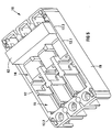
- the current transformer 33, the current sensing circuitry 36, the earth leakage sensing circuitry 38 and the shunt trip 40 are contained within a secondary housing 42 which is received in the part 12.3 of the housing 12 of the circuit breaker 10.
- the housing 42 is mounted above the core 20 in the part 12.3 of the housing 12 such that the tripping mechanism engages the operating handle of the circuit breaker 10.
- the arrangement of the oval-shaped core 20 parallel to the floor 18 of the base of the housing 12, and mounting of the secondary housing 42 above the core 12 facilitates the use of a housing 12 which has the same size as a conventional circuit breaker of the same rating but excluding an earth leakage facility.
- the output conductors 16 from the operating mechanism of the circuit breaker 10 are arranged with their usual spacing so that there is no need to provide additional insulation about the output conductors 16 nor is there a need to reduce their rating to overcome heating problems.
- circuit breaker 10 has been described with reference to electronic current sensing, it will be appreciated that the same configuration of earth leakage sensing facility can be also used with thermal-magnetic current sensing devices or hydraulic-magnetic current sensing devices.
Landscapes
- Engineering & Computer Science (AREA)
- Power Engineering (AREA)
- Breakers (AREA)
- Mechanisms For Operating Contacts (AREA)
Abstract
Description
Claims (11)
- A circuit breaker which includesa primary housing containing an operating mechanism, the operating mechanism including a plurality of output conductors;an earth leakage sensing means comprising an oval-shaped core mounted in the primary housing;electrically conductive elements, mounted on the output conductors and projecting through an oval-shaped opening defined by the core; andcurrent sensing circuitry and earth leakage sensing circuitry incorporated in a secondary housing, the secondary housing being received within the primary housing.
- The circuit breaker as claimed in Claim 1 in which the primary housing is dimensioned to be the same size as a housing and with the same size arc chutes of a circuit breaker of the same rating but excluding an earth leakage facility.
- The circuit breaker as claimed in Claim 1 or Claim 2 in which the primary housing includes a base having a floor bounded by a side wall portion, the core lying in a plane extending parallel to the floor.
- The circuit breaker as claimed in any one of the preceding claims in which the core is a strip-wound core of a nanocrystalline alloy.
- The circuit breaker as claimed in Claim 4 in which the core incorporates shielding material and insulating material.
- The circuit breaker as claimed in any one of the preceding claims in which each electrically conductive element is in the form of a spacer of an electrically conductive material, the spacers projecting through the opening of the core to be surrounded by the core.
- The circuit breaker as claimed in Claim 6 in which an output lug is mounted on each spacer.
- The circuit breaker as claimed in Claim 7 in which each output conductor is fastened to its associated spacer and output lug by a fastening means.
- The circuit breaker as claimed in Claim 7 or Claim 8 in which the current sensing circuitry includes a current sensing means.
- The circuit breaker as claimed in Claim 9 in which the current sensing means comprises a current transformer having a winding surrounding the output lugs.
- The circuit breaker as claimed in any one of the preceding claims in which the secondary housing is removably received in the primary housing.
Applications Claiming Priority (2)
| Application Number | Priority Date | Filing Date | Title |
|---|---|---|---|
| ZA978466 | 1997-09-19 | ||
| ZA9708466 | 1997-09-19 |
Publications (3)
| Publication Number | Publication Date |
|---|---|
| EP0903765A2 true EP0903765A2 (en) | 1999-03-24 |
| EP0903765A3 EP0903765A3 (en) | 1999-11-17 |
| EP0903765B1 EP0903765B1 (en) | 2002-11-13 |
Family
ID=25586600
Family Applications (1)
| Application Number | Title | Priority Date | Filing Date |
|---|---|---|---|
| EP98307415A Expired - Lifetime EP0903765B1 (en) | 1997-09-19 | 1998-09-14 | A circuit breaker |
Country Status (4)
| Country | Link |
|---|---|
| EP (1) | EP0903765B1 (en) |
| JP (1) | JPH11185593A (en) |
| AT (1) | ATE227883T1 (en) |
| DE (1) | DE69809359T2 (en) |
Cited By (1)
| Publication number | Priority date | Publication date | Assignee | Title |
|---|---|---|---|---|
| EP3435398A1 (en) * | 2017-07-25 | 2019-01-30 | Schneider Electric Industries SAS | Differential electrical protection apparatus |
Family Cites Families (2)
| Publication number | Priority date | Publication date | Assignee | Title |
|---|---|---|---|---|
| US5276416A (en) * | 1991-09-20 | 1994-01-04 | Kabushiki Kaisha Toshiba | Circuit breaker |
| GB9414873D0 (en) * | 1994-07-23 | 1994-09-14 | Delta Circuits Protection | Current imbalance sensor |
-
1998
- 1998-09-14 EP EP98307415A patent/EP0903765B1/en not_active Expired - Lifetime
- 1998-09-14 AT AT98307415T patent/ATE227883T1/en not_active IP Right Cessation
- 1998-09-14 DE DE69809359T patent/DE69809359T2/en not_active Expired - Lifetime
- 1998-09-16 JP JP10261098A patent/JPH11185593A/en active Pending
Cited By (5)
| Publication number | Priority date | Publication date | Assignee | Title |
|---|---|---|---|---|
| EP3435398A1 (en) * | 2017-07-25 | 2019-01-30 | Schneider Electric Industries SAS | Differential electrical protection apparatus |
| FR3069718A1 (en) * | 2017-07-25 | 2019-02-01 | Schneider Electric Industries Sas | DIFFERENTIAL ELECTRICAL PROTECTION APPARATUS |
| KR20190011672A (en) * | 2017-07-25 | 2019-02-07 | 슈나이더 일렉트릭 인더스트리스 에스에이에스 | Differential electrical protection device |
| US11017971B2 (en) | 2017-07-25 | 2021-05-25 | Schneider Electric Industries Sas | Differential electrical protection device that measures a differential current over a plurality of phase conductors |
| KR102549653B1 (en) | 2017-07-25 | 2023-06-29 | 슈나이더 일렉트릭 인더스트리스 에스에이에스 | Differential electrical protection device |
Also Published As
| Publication number | Publication date |
|---|---|
| EP0903765B1 (en) | 2002-11-13 |
| JPH11185593A (en) | 1999-07-09 |
| ATE227883T1 (en) | 2002-11-15 |
| DE69809359T2 (en) | 2003-09-04 |
| DE69809359D1 (en) | 2002-12-19 |
| EP0903765A3 (en) | 1999-11-17 |
Similar Documents
| Publication | Publication Date | Title |
|---|---|---|
| EP0966749B1 (en) | Circuit breaker having hall effect sensors | |
| US5303113A (en) | Digital circuit interrupter with RFI and EMI shielding | |
| CA2077826A1 (en) | Molded case circuit breaker with interchangeable trip circuits | |
| US7876181B2 (en) | Earth leakage circuit breaker | |
| AU745824B2 (en) | Miniaturized double pole circuit breaker with arc fault and ground fault protection | |
| US5583732A (en) | Modular current transformer for electronic circuit interrupters | |
| RU2329561C1 (en) | Device of protective disconnection of narrow structural version | |
| IE950037A1 (en) | A circuit breaker | |
| CA2005529C (en) | Molded case circuit interrupter rating plug keying and interlock arrangement | |
| EP2724433B1 (en) | Grounded circuit breaker panel electrical module and method for grounding same | |
| US5889450A (en) | Current transformer assembly for electronic circuit interrupters | |
| US20070158171A1 (en) | Control module | |
| EP0903765B1 (en) | A circuit breaker | |
| US7948724B2 (en) | Current transformer support bracket and circuit interrupter including the same | |
| EP0610044B1 (en) | Molded case circuit breaker modular line strap assembly | |
| EP1034590B1 (en) | Modular protective relay with submodules | |
| US6108185A (en) | Circuit breaker having hall effect sensors | |
| AU2008261117B2 (en) | Modular protection unit comprising a complementary electrical function such as the differential protection function | |
| US5485134A (en) | Auxiliary switch accessory module unit for high ampere-rated circuit breaker | |
| IE892175L (en) | Ct quick change assembly | |
| ATE50097T1 (en) | ELECTRICAL INSTALLATION WITH OVERVOLTAGE PROTECTION. | |
| GB1583732A (en) | Circuit breakers | |
| CN1954221A (en) | Earth leakage detection device | |
| US11972918B1 (en) | Two-section conductor type ground fault circuit interrupter with reverse wiring protection function | |
| WO2001088938A2 (en) | Cable lug conductor adapter device |
Legal Events
| Date | Code | Title | Description |
|---|---|---|---|
| PUAI | Public reference made under article 153(3) epc to a published international application that has entered the european phase |
Free format text: ORIGINAL CODE: 0009012 |
|
| AK | Designated contracting states |
Kind code of ref document: A2 Designated state(s): AT DE FR GB IT NL SE |
|
| AX | Request for extension of the european patent |
Free format text: AL;LT;LV;MK;RO;SI |
|
| PUAL | Search report despatched |
Free format text: ORIGINAL CODE: 0009013 |
|
| AK | Designated contracting states |
Kind code of ref document: A3 Designated state(s): AT BE CH CY DE DK ES FI FR GB GR IE IT LI LU MC NL PT SE |
|
| AX | Request for extension of the european patent |
Free format text: AL;LT;LV;MK;RO;SI |
|
| 17P | Request for examination filed |
Effective date: 19991124 |
|
| AKX | Designation fees paid |
Free format text: AT DE FR GB IT NL SE |
|
| GRAG | Despatch of communication of intention to grant |
Free format text: ORIGINAL CODE: EPIDOS AGRA |
|
| 17Q | First examination report despatched |
Effective date: 20020328 |
|
| GRAG | Despatch of communication of intention to grant |
Free format text: ORIGINAL CODE: EPIDOS AGRA |
|
| GRAH | Despatch of communication of intention to grant a patent |
Free format text: ORIGINAL CODE: EPIDOS IGRA |
|
| GRAH | Despatch of communication of intention to grant a patent |
Free format text: ORIGINAL CODE: EPIDOS IGRA |
|
| GRAA | (expected) grant |
Free format text: ORIGINAL CODE: 0009210 |
|
| AK | Designated contracting states |
Kind code of ref document: B1 Designated state(s): AT DE FR GB IT NL SE |
|
| REF | Corresponds to: |
Ref document number: 227883 Country of ref document: AT Date of ref document: 20021115 Kind code of ref document: T |
|
| REG | Reference to a national code |
Ref country code: GB Ref legal event code: FG4D |
|
| REF | Corresponds to: |
Ref document number: 69809359 Country of ref document: DE Date of ref document: 20021219 |
|
| ET | Fr: translation filed | ||
| PLBE | No opposition filed within time limit |
Free format text: ORIGINAL CODE: 0009261 |
|
| STAA | Information on the status of an ep patent application or granted ep patent |
Free format text: STATUS: NO OPPOSITION FILED WITHIN TIME LIMIT |
|
| 26N | No opposition filed |
Effective date: 20030814 |
|
| PGFP | Annual fee paid to national office [announced via postgrant information from national office to epo] |
Ref country code: SE Payment date: 20090910 Year of fee payment: 12 Ref country code: NL Payment date: 20090903 Year of fee payment: 12 Ref country code: GB Payment date: 20090909 Year of fee payment: 12 Ref country code: AT Payment date: 20090911 Year of fee payment: 12 |
|
| PGFP | Annual fee paid to national office [announced via postgrant information from national office to epo] |
Ref country code: DE Payment date: 20090910 Year of fee payment: 12 |
|
| PGFP | Annual fee paid to national office [announced via postgrant information from national office to epo] |
Ref country code: IT Payment date: 20090915 Year of fee payment: 12 Ref country code: FR Payment date: 20091012 Year of fee payment: 12 |
|
| REG | Reference to a national code |
Ref country code: NL Ref legal event code: V1 Effective date: 20110401 |
|
| REG | Reference to a national code |
Ref country code: SE Ref legal event code: EUG |
|
| GBPC | Gb: european patent ceased through non-payment of renewal fee |
Effective date: 20100914 |
|
| PG25 | Lapsed in a contracting state [announced via postgrant information from national office to epo] |
Ref country code: IT Free format text: LAPSE BECAUSE OF NON-PAYMENT OF DUE FEES Effective date: 20100914 |
|
| REG | Reference to a national code |
Ref country code: FR Ref legal event code: ST Effective date: 20110531 |
|
| REG | Reference to a national code |
Ref country code: DE Ref legal event code: R119 Ref document number: 69809359 Country of ref document: DE Effective date: 20110401 |
|
| PG25 | Lapsed in a contracting state [announced via postgrant information from national office to epo] |
Ref country code: DE Free format text: LAPSE BECAUSE OF NON-PAYMENT OF DUE FEES Effective date: 20110401 Ref country code: FR Free format text: LAPSE BECAUSE OF NON-PAYMENT OF DUE FEES Effective date: 20100930 |
|
| PG25 | Lapsed in a contracting state [announced via postgrant information from national office to epo] |
Ref country code: AT Free format text: LAPSE BECAUSE OF NON-PAYMENT OF DUE FEES Effective date: 20100914 Ref country code: NL Free format text: LAPSE BECAUSE OF NON-PAYMENT OF DUE FEES Effective date: 20110401 Ref country code: GB Free format text: LAPSE BECAUSE OF NON-PAYMENT OF DUE FEES Effective date: 20100914 |
|
| PG25 | Lapsed in a contracting state [announced via postgrant information from national office to epo] |
Ref country code: SE Free format text: LAPSE BECAUSE OF NON-PAYMENT OF DUE FEES Effective date: 20100915 |