EP0903707B1 - In-bed state detection system - Google Patents
In-bed state detection system Download PDFInfo
- Publication number
- EP0903707B1 EP0903707B1 EP98117439A EP98117439A EP0903707B1 EP 0903707 B1 EP0903707 B1 EP 0903707B1 EP 98117439 A EP98117439 A EP 98117439A EP 98117439 A EP98117439 A EP 98117439A EP 0903707 B1 EP0903707 B1 EP 0903707B1
- Authority
- EP
- European Patent Office
- Prior art keywords
- bed
- state
- detection system
- load
- section
- Prior art date
- Legal status (The legal status is an assumption and is not a legal conclusion. Google has not performed a legal analysis and makes no representation as to the accuracy of the status listed.)
- Expired - Lifetime
Links
Images


Classifications
-
- G—PHYSICS
- G08—SIGNALLING
- G08B—SIGNALLING OR CALLING SYSTEMS; ORDER TELEGRAPHS; ALARM SYSTEMS
- G08B21/00—Alarms responsive to a single specified undesired or abnormal condition and not otherwise provided for
- G08B21/18—Status alarms
- G08B21/22—Status alarms responsive to presence or absence of persons
Description
- The present invention relates to an in-bed state detection system for detecting how a human is situated in a bed.
- In hospitals, facilities for the aged, etc., it is often necessary to know whether a person is in bed or out of bed and wandering somewhere, for example. Therefore, nurses or the like may be required to make rounds to rooms accommodating one or more beds.
- Japanese Laid-open Utility Model Publication No. 4-30504 discloses an apparatus for monitoring whether or not a person is in bed. This publication discloses a plurality of pyroelectric infrared sensors and thermopiles which are disposed by the bedside and horizontally to the pillow.
- However, there has not been proposed any effective method which is intended for a high-quality care based on various states of sleep of a patient for detecting whether the patient (hospitalized or otherwise) on a bed is fast asleep or lacking sleep, or in an abnormal state (e.g., having strokes of a certain disease, convulsion, etc.).
- An in-bed state detection system according to the present invention includes: a load detection section for US 4,179,692 discloses a switch placed in a bed under a patient, including contacts which can make or break a connection to a signal processing circuit which charges a capacitor at a selected rate, when the switch is in a first state and discharges the capacitor when the switch is in a second state. A latch is set to actuate a signal when the voltage of the capacitor reaches a selected high value. By controlling the rates of charge and discharge of the capacitor it is possible to provide an indication of the degree of restlessness of the patient, the presence of the patient in bed, and whether the patient is out of bed.
- US 5,590,650 discloses an apparatus operable for monitoring physiological vital signs of a human body without physically contacting the body. The apparatus includes a sensor operable to transform a movement and/or acoustical wave produced by the body into an electrical signal, a signal processor coupled to the sensor and operable to receive the electrical signal from the sensor and to process the electrical signal adaptively using wavelet correlator analysis. The signal processor provides an output signal indicative of the movement and/or acoustical wave producing the electrical signal. This apparatus can be used to monitor heart rate, respiration rate and related sounds, digestive system sounds as well as other pysiological vital signs for the evaluation of the health of a person.
- US 4,657,026 discloses an apnea alarm apparatus detecting the cessation of breathing of a human by monitoring movement of the ribcage by a sensor. The sensor is connected to a summing amplifier providing an electrical signal indicative of the breathing movement of the ribcage.
- US 5,479,939 discloses to detect movement of a person in bed without contacting the body and a time measurement is reset and started newly by a timer every time a detected movement exceeds a predetermined set value. When the measurement time of the timer exceeds a predetermined set time, it is judged the body has fallen asleep on the bed. According to an embodiment a presence judging means is additionally provided to a body movement detecting means.
- The present invention relates to an in-bed state detection system for detecting how a human is situated in a bed.
- In hospitals, facilities for the aged, etc., it is often necessary to know whether a person is in bed or out of bed and wandering somewhere, for example. Therefore, nurses or the like may be required to make rounds to rooms accommodating one or more beds.
- Japanese Laid-open Utility Model Publication No. 4-30504 discloses an apparatus for monitoring whether or not a person is in bed. This publication discloses a plurality of pyroelectric infrared sensors and thermopiles which are disposed by the bedside and horizontally to the pillow.
- However, there has not been proposed any effective method which is intended for a high-quality care based on various states of sleep of a patient for detecting whether the patient (hospitalized or otherwise) on a bed is fast asleep or lacking sleep, or in an abnormal state (e.g., having strokes of a certain disease, convulsion, etc.).
- An in-bed state detection system according to the present invention is defined by the features in
claim 1. - In one embodiment of the invention, the load detection section is provided between the bed and a floor on which the bed is placed.
- In another embodiment of the invention, the in-bed state detection system further includes means for indicating the in-bed state via sounds and/or light.
- In still another embodiment of the invention, the transmission section includes an electromagnetic signal transmitter and an electromagnetic signal receiver, the electromagnetic signal transmitter being disposed on the bed, and the electromagnetic signal receiver being disposed at a location other than on the bed.
- In still another embodiment of the invention, the determination section differentiates the load signal by time and determines the in-bed state based on an output intensity and temporal distribution of a signal resulting from differentiation of the load signal.
- In still another embodiment of the invention, the determination section determines the in-bed state based on an amplitude and a frequency of the load signal.
- In still another embodiment of the invention, the in-bed state is at least one of a "fast asleep" state, a "lacking sleep" state, a "convulsive" state, a "frantic" state, and a "periodic strokes" state.
- In still another embodiment of the invention, the in-bed state detection system further includes a central control unit for receiving the result of the determination transmitted from the transmission section and displaying the result, the central control unit being disposed in a room other than a room in which the bed is placed.
- Thus, the invention described herein makes possible the advantage of providing an in-bed state detection system for detecting how a human is situated in a bed.
- This and other advantages of the present invention will become apparent to those skilled in the art upon reading and understanding the following detailed description with reference to the accompanying figures.
-
- Figure 1 is a diagram illustrating an in-bed state detection system according to Example 1 of the present invention.
- Figure 2 is a graph illustrating a load applied versus time.
- Figure 3 is a set of graphs illustrating loads applied versus time in various in-bed states.
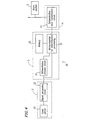
- Figure 4 is a diagram illustrating an in-bed state detection system according to Example 2 of the present invention.
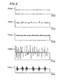
- Figure 5 is a set of graphs illustrating exemplary waveforms versus time in various in-bed states, where the waveforms are obtained by differentiating a load signal by time.
- Figure 6 is a diagram illustrating an in-bed state detection system according to Example 3 of the present invention.
-
- An in-bed
state detection system 10 according to a first example of the present invention will be described with reference to the figures. - Figure 1 is a diagram illustrating the in-bed
state detection system 10. The in-bedstate detection system 10 includes aload detection section 2, an in-bedstate determination section 3, and atransmission section 4. Theload detection section 2, which detects the load applied on at least oneleg 1a of abed 1, is disposed between that leg and the floor. A load signal representing the load detected by theload detection section 2 is sent to and analyzed by the in-bedstate determination section 3. The result of analysis is sent by thetransmission section 4 to the outside of the room in which thebed 1 is placed. - Figure 2 is a graph illustrating the load applied to a leg of a bed versus time. Specifically, Figure 2 illustrates a person getting in bed at time t1 and getting out of bed at time t2.
- The in-bed
state determination section 3 determines whether a person is in bed or out of bed based on the load signal detected by theload detection section 2. If the detected load signal is equal to or greater than a threshold value A shown in Figure 2, the in-bedstate determination section 3 determines that the person is in bed; if the detected load signal is smaller than a threshold value A shown in Figure 2, the in-bedstate determination section 3 determines that the person is out of bed. - Furthermore, the in-bed
state determination section 3 determines the in-bed state of a person who is in bed. - Herein, the in-bed state refers to a state of a person who is in bed, e.g., "fast asleep", "lacking sleep", "convulsive" , "frantic (i.e., under an aperiodic stroke)", or "periodic strokes".
- Figure 3 is a set of graphs illustrating loads applied versus time in various in-bed states.
- In Figure 3,
pattern 1 shows a "fast asleep" state, where the body of the person in bed is in substantially no motion.Pattern 2 shows a "lacking sleep" state, where the magnitude of the detected load signal undergoes a periodic variation (i.e., the person in bed keeps repositioning through turning over, etc.).Pattern 3 shows a "convulsive" state, where the person in bed is having a convulsion (i.e., the body of the person is making minute movements).Pattern 4 shows a "frantic" (under an aperiodic stroke) state, where the person in bed is having an aperiodic stroke or moving about violently.Pattern 5 shows a "periodic strokes" state, where the person in bed is having periodic strokes. - The in-bed
state determination section 3 determines at least one of the above-mentioned states based on the detected load signal. The in-bedstate determination section 3 may include a first table, against which one of the above states is to be determined based on the amplitude and frequency of the detected load signal. For example, the first table may indicate that a pattern satisfying the condition "A1 ≤ amplitude of the detected load signal < A2" and the condition "C1 ≤ frequency of the detected load signal < C2" ispattern 2. In this case, the in-bedstate determination section 3 determines that a person in bed whose sensed motion satisfies these conditions is in a "lacking sleep" state. Alternatively, the in-bedstate determination section 3 may detect movement of the person in bed based on the magnitude of the absolute value of the detected load signal, and determine one of the above states based on the temporal distribution of the detected load signal. - Although the
load detection section 2 in Figure 1 may be disposed between a caster on a leg of the bed and the floor, a mechanism for detecting a load applied to a leg of the bed may alternatively be provided within the leg. - The in-bed
state determination section 3 and thesignal transmission section 4 may be implemented as one integral means. - An in-bed
state detection system 20 according to a second example of the present invention will be described with reference to the figures. - Figure 4 is a diagram illustrating the in-bed
state detection system 20. The in-bedstate detection system 20 includes aload detection section 2, an in-bedstate determination section 3, and atransmission section 4. - The
load detection section 2 includes aload sensor 21 and asignal processing circuit 22. Theload sensor 21 can be implemented based on a strain resistor, a load cell, or a modified coil spring. Theload sensor 21 detects the load applied to a leg of abed 1. The signal representing the detected load is shaped by thesignal processing circuit 22, and sent to the in-bedstate determination section 3 as a load signal. - The in-bed
state determination section 3 includes a microcomputer 32 (including an A/D convertor) for determination processing , and amemory 33. Themicrocomputer 32 receives the load signal from thesignal processing circuit 22 and determines the in-bed state based thereon. - The
memory 33 stores a comparison threshold value or a table as required for the determination of the in-bed state. - The in-bed
state determination section 3 may include adifferentiation process circuit 31 as illustrated in Figure 4. In the case where the in-bedstate determination section 3 includes adifferentiation process circuit 31, thedifferentiation process circuit 31 receives a load signal and subjects the load signal to differentiation by time, so as to send a resultant signal (hereinafter "differentiation signal") to themicrocomputer 32. Themicrocomputer 32 receives the differentiation signal and determines the in-bed state based thereon. Alternatively, themicrocomputer 32 may determine the in-bed state based on the load signal. - The differentiation of the load signal may be performed in the
microcomputer 32 instead of thedifferentiation process circuit 31. - Hereinafter, the temporal relationship of the waveform (pulses) obtained by differentiating a load signal by time will be described with respect to various in-bed states.
- Figure 5 is a set of graphs illustrating exemplary waveforms versus time in various in-bed states, where the waveforms are obtained by differentiating a load signal by time. In Figure 5,
pattern 1 shows a "fast asleep" state;pattern 2 shows a "lacking sleep" state;pattern 3 shows a "convulsive" state;pattern 4 shows a "frantic" (under an unperiodic stroke) state; andpattern 5 shows a "periodic strokes" state. - The
microcomputer 32 determines at least one of the above-mentioned states based on the waveform (pulses) obtained by differentiating the load signal by time via thedifferentiation process circuit 31. Thememory 33 may include a second table against which themicrocomputer 32 determines at least one of the above-mentioned patterns based on the output intensity and temporal distribution of the pulses. For example, the second table may indicate that a pattern satisfying the condition "I1 ≤ output intensity < I2" and the condition "D1 ≤ temporal distribution density < D2" ispattern 2. In this case, themicrocomputer 32 determines that a person in bed whose sensed motion satisfies these conditions is in a "lacking sleep" state. Specifically, themicrocomputer 32 calls the table stored in thememory 33 to compare the output intensity and the temporal distribution of the aforementioned pulses against the table, thereby determining a state which corresponds to the specific output intensity and temporal distribution of the pulses. - Alternatively, the
microcomputer 32 may detect the in-bed state based on the differentiation signal and the load signal. Such an in-bed state detection system can accurately determine the in-bed state. In this case, thememory 33 includes the first table (according to Example 1) as well as the second table. - The results determined by the
microcomputer 32 are output by a determinationdata transmission circuit 41 in the transmission section 4 (Figure 4) to a designated location outside of the room in which thebed 1 is placed. The result of determination by themicrocomputer 32 may be a digital value. - Optionally, the in-bed
state detection system 20 may include analarm section 5. Thealarm section 5 indicates the in-bed state of a person to another via sounds (defined herein as encompassing any audible sounds including voices, etc.) and/or light, based on the result of determination by themicrocomputer 32. The indication or alarm via sounds and/or light can be continuous or intermittent. The in-bedstate detection system 20 may also include an alarm disengagement section for stopping the alarm after the in-bed state of the person in bed has been confirmed by another. - The
load sensor 21, e.g., a load cell, may be disposed between a caster on a leg of the bed and the floor. Alternatively, a mechanism for detecting a load applied to a leg of the bed may alternatively be provided within the leg. - The in-bed
state determination section 3 and thesignal transmission section 4 may be implemented as one integral means. - An in-bed
state detection system 50 according to a third example of the present invention will be described with reference to the figures. - Figure 6 is a diagram illustrating the in-bed
state detection system 50. The in-bedstate detection system 50 includesload detection sections 2, in-bedstate determination sections 3,transmission sections 4,alarm sections 5,alarm disengagement sections 6, and acentral control unit 51. Theload detection sections 2, the in-bedstate determination sections 3, thetransmission sections 4, thealarm sections 5, and thealarm disengagement sections 6 are of the same construction as that of their corresponding components in Examples 1 and/or 2. It is assumed that the in-bedstate detection system 50 is installed in a hospital, a facility for the aged, etc., having a plurality of rooms, with thecentral control unit 51 being located in a room other than any of the rooms accommodating one or more beds. - Each
load detection section 2 is located in a bed room accommodating at least one bed. More specifically, theload detection section 2, which detects the load applied on at least one leg (i.e.,leg 1a) of thebed 1, is disposed between that leg and the floor. All or part of theload detection section 2 is located inside or outside the room. As in Examples 1 and 2, each in-bedstate determination section 3 is capable of determining the respective in-bed states based on load signals output from a plurality ofload detection sections 2. The results of determination are sent by eachtransmission section 4 to the outside of the corresponding room. Specifically, the results of determination are sent to thecentral control unit 51 via an IFU (interface unit) 52 and wiring 53 (e.g., Ethernet). Thecentral control unit 51 includes a monitor (not shown) indicating the in-bed states of the respective patients. Thecentral control unit 51 may be located in a nurse station for monitoring the patients. Nurses, doctors, and others standing by in the nurse station can know the in-bed states of the respective patients in real time. - An
alarm section 5 may be provided in the vicinity of thecentral control unit 51 for indicating the results of determination. Thealarm section 5, using sounds and/or light, indicates any state that may be hazardous to the life of each patient, e.g., a "convulsive" state, a "frantic" (under an aperiodic stroke) state, or a "periodic strokes" state, to those standing by in the nurse station. The indication or alarm via sounds and/or light can be made continuously or intermittently. - The
alarm disengagement sections 6 for stopping the alarm may be located in a hallway between the nurse station and the rooms accommodating beds for patients. Thus, once a doctor, a nurse, or the like, has directly confirmed the state of a patient, he or she can stop the alarm indicated by thealarm section 5 via thealarm disengagement section 6 located in the hallway, without returning to the nurse station. - Optionally, monitor cameras or the like (not shown) for indirectly monitoring the states of the respective patients may be provided in each room. The
central control unit 51 may be provided with a function of stopping alarms. Thus, once a doctor, a nurse, or the like has confirmed the safe condition of a patient via images from a monitor camera displayed on a monitor display located in the nurse center or the like, he or she can stop the alarm by means of thecentral control unit 51. - Furthermore, the monitor cameras and the monitor display may be arranged so as to automatically begin displaying a patient who has entered a state that may be hazardous to the life of each patient, e.g., a "convulsive" state, a "frantic" (under an aperiodic stroke) state, or a "periodic strokes" state.
- As the
transmission section 4 for transmitting results of determination by the in-bedstate determination section 3 to the outside, an electromagnetic signal transmitter and an electromagnetic signal receiver may be used. Such an electromagnetic signal transmitter may be disposed on the bed frame or the bed body. The electromagnetic signal transmitter receives the result of determination from the in-bedstate determination section 3 and transmits it to the electromagnetic signal receiver disposed, for example, on the ceiling, wall, or the floor of the room. The result of determination received by the electromagnetic signal receiver is sent to thecentral control unit 51 via theIFU 52. This arrangement allows for a substantially unrestricted layout of beds within each room. - In Examples 1 to 3, the load which is applied to at least one leg of the bed is detected. Therefore, it will be appreciated that the in-bed state detection system of the present invention can detect the load applied to each of any two or more legs of the bed and determine the in-bed state based on these load values.
- The in-bed state detection system according to the present invention determines the in-bed state of a person in bed based on a detected load signal, and transmits the result of determination to the outside of the room in which the bed is placed. This eliminates the need for another person to stand by in the room in order to monitor the state of the person who is in bed.
- The in-bed state detection system according to the present invention can include an alarm section for indicating or alarming any of the aforementioned in-bed states via sounds and/or light. Therefore, even if a patient encounters a stroke or convulsion so that he or she cannot even utter a sound for help, the alarm section can call for help instead of the patient.
Claims (8)
- An in-bed state detection system comprising:wherein the determination section (3) comprises a memory (33) which stores a table for the determination of the specific in-bed states, anda load detection section (2) for detecting a load applied to a bed (1) and providing a corresponding load signal;a determination section (3) for determining an in-bed state based on the load signal; anda transmission section (4) for transmitting a result of the determination,
wherein the determination section (3) differentiates the load signal by time and determines the in-bed state based on the comparison of an output intensity and temporal distribution of a signal resulting from differentiation of the load signal with values stored in the table,
wherein said values correspond to specific in-bed states. - An in-bed state detection system according to claim 1, wherein the load detection section (2) is provided between the bed (1) and a floor on which the bed (1) is placed.
- An in-bed state detection system according to claim 1 or 2 further comprising means for indicating the in-bed state via sounds and/or light.
- An in-bed state detection system according to one of claims 1 to 3, wherein
the transmission section (4) includes an electromagnetic signal transmitter and an electromagnetic signal receiver,
the electromagnetic signal transmitter being disposed on the bed (1), and
the electromagnetic signal receiver being disposed at a location other than on the bed. - An in-bed state detection system according to one of claims 1 to 4, wherein the determination section determines the in-bed state based on an amplitude and a frequency of the load signal.
- An in-bed state detection system according to one of claims 1 to 5, wherein the in-bed state is at least one of a "fast asleep" state, a "lacking sleep" state, a "convulsive" state, a "frantic" state, and a "periodic strokes" state.
- An in-bed state detection system according to one of claims 1 to 6, further comprising a central control unit for receiving the result of the determination transmitted from the transmission section (4) and displaying the result,
the central control unit being disposed in a room other than a room in which the bed is placed. - A bed having the in-bed state detection system according to one of claims 1 to 7.
Applications Claiming Priority (3)
| Application Number | Priority Date | Filing Date | Title |
|---|---|---|---|
| JP25198197 | 1997-09-17 | ||
| JP251981/97 | 1997-09-17 | ||
| JP25198197 | 1997-09-17 |
Publications (3)
| Publication Number | Publication Date |
|---|---|
| EP0903707A2 EP0903707A2 (en) | 1999-03-24 |
| EP0903707A3 EP0903707A3 (en) | 1999-08-25 |
| EP0903707B1 true EP0903707B1 (en) | 2004-02-04 |
Family
ID=17230889
Family Applications (1)
| Application Number | Title | Priority Date | Filing Date |
|---|---|---|---|
| EP98117439A Expired - Lifetime EP0903707B1 (en) | 1997-09-17 | 1998-09-15 | In-bed state detection system |
Country Status (4)
| Country | Link |
|---|---|
| US (1) | US6239706B1 (en) |
| EP (1) | EP0903707B1 (en) |
| KR (1) | KR100310928B1 (en) |
| DE (2) | DE69821422T2 (en) |
Families Citing this family (50)
| Publication number | Priority date | Publication date | Assignee | Title |
|---|---|---|---|---|
| CA2327000C (en) * | 2000-11-27 | 2006-05-09 | Terry Cassaday | Chair or bed member having data storage |
| US6825769B2 (en) * | 2001-09-14 | 2004-11-30 | Koninklijke Philips Electronics N.V. | Automatic shut-off light system when user sleeps |
| US6788206B1 (en) | 2002-09-05 | 2004-09-07 | Donald A. Edwards | Patient monitoring system |
| SE0203483D0 (en) * | 2002-11-21 | 2002-11-21 | Wespot Ab | Method and device for fall detection |
| CA2516093C (en) * | 2003-02-28 | 2012-05-01 | Consolidated Research Of Richmond, Inc. | Automated insomnia treatment system |
| US8512221B2 (en) * | 2003-02-28 | 2013-08-20 | Consolidated Research Of Richmond, Inc. | Automated treatment system for sleep |
| JP3960298B2 (en) * | 2003-11-19 | 2007-08-15 | 株式会社デンソー | Sleeping and posture detection device |
| US7314451B2 (en) | 2005-04-25 | 2008-01-01 | Earlysense Ltd. | Techniques for prediction and monitoring of clinical episodes |
| JP4809779B2 (en) * | 2004-02-05 | 2011-11-09 | アーリーセンス・リミテッド | Prediction and monitoring technology for clinical onset in respiration |
| US8403865B2 (en) | 2004-02-05 | 2013-03-26 | Earlysense Ltd. | Prediction and monitoring of clinical episodes |
| US20070118054A1 (en) * | 2005-11-01 | 2007-05-24 | Earlysense Ltd. | Methods and systems for monitoring patients for clinical episodes |
| US8942779B2 (en) | 2004-02-05 | 2015-01-27 | Early Sense Ltd. | Monitoring a condition of a subject |
| US8491492B2 (en) | 2004-02-05 | 2013-07-23 | Earlysense Ltd. | Monitoring a condition of a subject |
| US20060019224A1 (en) * | 2004-07-23 | 2006-01-26 | Pics, Inc. | Insomnia assessment and treatment device and method |
| US7253366B2 (en) * | 2004-08-09 | 2007-08-07 | Hill-Rom Services, Inc. | Exit alarm for a hospital bed triggered by individual load cell weight readings exceeding a predetermined threshold |
| KR100712198B1 (en) * | 2005-02-17 | 2007-04-30 | 재단법인서울대학교산학협력재단 | Apparatus for analyzing a sleep structure according to non-constrained weight detection |
| DE102005011706A1 (en) * | 2005-03-11 | 2006-09-28 | Klugmann, Gerhard | Nursing place monitoring method, involves activating sensors arranged at sick person`s bed and transferring integral picture of person`s attitude for evaluation, where total information is conducted to evaluation unit |
| WO2006101275A1 (en) * | 2005-03-24 | 2006-09-28 | Showa Denko K.K. | Bed load detector |
| WO2006135845A2 (en) | 2005-06-10 | 2006-12-21 | Hill-Rom Services, Inc. | Control for pressurized bladder in a patient support apparatus |
| EP2154658A1 (en) | 2005-10-11 | 2010-02-17 | Quick Sensor NV | Occupation monitoring system |
| JP4514717B2 (en) * | 2006-01-20 | 2010-07-28 | パラマウントベッド株式会社 | A bed apparatus equipped with a bed prediction and detection system |
| US7849545B2 (en) * | 2006-11-14 | 2010-12-14 | Hill-Rom Industries Sa | Control system for hospital bed mattress |
| US8585607B2 (en) | 2007-05-02 | 2013-11-19 | Earlysense Ltd. | Monitoring, predicting and treating clinical episodes |
| JP5115991B2 (en) | 2008-04-30 | 2013-01-09 | 独立行政法人産業技術総合研究所 | Object state detection apparatus and method |
| US8882684B2 (en) | 2008-05-12 | 2014-11-11 | Earlysense Ltd. | Monitoring, predicting and treating clinical episodes |
| US9883809B2 (en) | 2008-05-01 | 2018-02-06 | Earlysense Ltd. | Monitoring, predicting and treating clinical episodes |
| EP2286395A4 (en) * | 2008-05-12 | 2013-05-08 | Earlysense Ltd | Monitoring, predicting and treating clinical episodes |
| US10335060B1 (en) | 2010-06-19 | 2019-07-02 | Dp Technologies, Inc. | Method and apparatus to provide monitoring |
| US8783114B2 (en) * | 2010-07-14 | 2014-07-22 | Healthsense, Inc. | Occupancy sensor |
| US8717181B2 (en) | 2010-07-29 | 2014-05-06 | Hill-Rom Services, Inc. | Bed exit alert silence with automatic re-enable |
| US10292625B2 (en) | 2010-12-07 | 2019-05-21 | Earlysense Ltd. | Monitoring a sleeping subject |
| US9013313B2 (en) * | 2011-01-18 | 2015-04-21 | Alan Paine | Bed pre-exit patient monitor |
| US9192326B2 (en) | 2011-07-13 | 2015-11-24 | Dp Technologies, Inc. | Sleep monitoring system |
| US9459597B2 (en) | 2012-03-06 | 2016-10-04 | DPTechnologies, Inc. | Method and apparatus to provide an improved sleep experience by selecting an optimal next sleep state for a user |
| US10791986B1 (en) | 2012-04-05 | 2020-10-06 | Dp Technologies, Inc. | Sleep sound detection system and use |
| US10292605B2 (en) | 2012-11-15 | 2019-05-21 | Hill-Rom Services, Inc. | Bed load cell based physiological sensing systems and methods |
| US9474876B1 (en) | 2012-12-14 | 2016-10-25 | DPTechnologies, Inc. | Sleep aid efficacy |
| US9713559B2 (en) | 2013-03-15 | 2017-07-25 | Stryker Corporation | Medical support apparatus |
| US9320444B2 (en) | 2013-03-15 | 2016-04-26 | Stryker Corporation | Patient support apparatus with patient information sensors |
| US10376214B2 (en) | 2013-03-15 | 2019-08-13 | Stryker Corporation | Patient support apparatus with patient information sensors |
| US9594354B1 (en) | 2013-04-19 | 2017-03-14 | Dp Technologies, Inc. | Smart watch extended system |
| EP2995242B1 (en) | 2014-09-11 | 2023-11-15 | Hill-Rom S.A.S. | Patient support apparatus |
| EP3206654B1 (en) * | 2014-10-17 | 2020-11-25 | Stryker Corporation | Person support apparatuses with motion monitoring |
| US9468399B2 (en) | 2014-12-09 | 2016-10-18 | SensaRx, LLC | Detection of changes from a seated or lying body position by sensing body angle |
| US11883188B1 (en) | 2015-03-16 | 2024-01-30 | Dp Technologies, Inc. | Sleep surface sensor based sleep analysis system |
| US10078952B2 (en) * | 2015-11-02 | 2018-09-18 | Patrick John O'Keefe, JR. | Bed check device and method of use |
| US9679462B1 (en) | 2015-12-20 | 2017-06-13 | Christopher Robertson | Wireless wake-up alarm with occupant-sensing apparatus |
| EP3205268B1 (en) | 2016-02-11 | 2023-10-25 | Hill-Rom Services, Inc. | Hospital bed |
| EP3518854A4 (en) * | 2016-11-28 | 2020-09-02 | Verb Surgical Inc. | Robotic surgical system to reduce unwanted vibration |
| US11382534B1 (en) | 2018-10-15 | 2022-07-12 | Dp Technologies, Inc. | Sleep detection and analysis system |
Family Cites Families (13)
| Publication number | Priority date | Publication date | Assignee | Title |
|---|---|---|---|---|
| US4263586A (en) * | 1976-08-20 | 1981-04-21 | Noel Nicholas | Pressure operated electric switch and alarm system using such switch |
| US4179692A (en) * | 1977-05-05 | 1979-12-18 | Vance Dwight A | Apparatus to indicate when a patient has evacuated a bed or demonstrates a restless condition |
| US4320766A (en) * | 1979-03-13 | 1982-03-23 | Instrumentarium Oy | Apparatus in medicine for the monitoring and or recording of the body movements of a person on a bed, for instance of a patient |
| US4633237A (en) * | 1984-07-11 | 1986-12-30 | Kenneth A. Tucknott | Patient bed alarm system |
| US4738264A (en) * | 1985-03-25 | 1988-04-19 | Carl Orlando | Heart and breathing alarm monitor |
| US4638307A (en) * | 1985-10-15 | 1987-01-20 | Swartout Willson C | Patient position monitoring system |
| US4657026A (en) * | 1986-07-14 | 1987-04-14 | Tagg James R | Apnea alarm systems |
| CA2056370C (en) * | 1990-03-09 | 1998-08-11 | Hiroyuki Ogino | Sleep detecting apparatus |
| JP2906075B2 (en) | 1990-05-28 | 1999-06-14 | 戸田工業株式会社 | Manufacturing method of magnetic particle powder for magnetic recording |
| JPH04153799A (en) | 1990-10-17 | 1992-05-27 | Fuji Electric Co Ltd | Person's whereabouts detector and one's whereabouts monitoring system |
| US5276432A (en) * | 1992-01-15 | 1994-01-04 | Stryker Corporation | Patient exit detection mechanism for hospital bed |
| US5590650A (en) * | 1994-11-16 | 1997-01-07 | Raven, Inc. | Non-invasive medical monitor system |
| US5853005A (en) * | 1996-05-02 | 1998-12-29 | The United States Of America As Represented By The Secretary Of The Army | Acoustic monitoring system |
-
1998
- 1998-09-15 DE DE69821422T patent/DE69821422T2/en not_active Expired - Lifetime
- 1998-09-15 DE DE0903707T patent/DE903707T1/en active Pending
- 1998-09-15 EP EP98117439A patent/EP0903707B1/en not_active Expired - Lifetime
- 1998-09-16 US US09/154,493 patent/US6239706B1/en not_active Expired - Lifetime
- 1998-09-16 KR KR1019980038145A patent/KR100310928B1/en not_active IP Right Cessation
Also Published As
| Publication number | Publication date |
|---|---|
| DE903707T1 (en) | 1999-12-09 |
| US6239706B1 (en) | 2001-05-29 |
| KR19990029820A (en) | 1999-04-26 |
| EP0903707A3 (en) | 1999-08-25 |
| EP0903707A2 (en) | 1999-03-24 |
| KR100310928B1 (en) | 2001-12-28 |
| DE69821422D1 (en) | 2004-03-11 |
| DE69821422T2 (en) | 2004-12-30 |
Similar Documents
| Publication | Publication Date | Title |
|---|---|---|
| EP0903707B1 (en) | In-bed state detection system | |
| US6160478A (en) | Wireless health monitoring system | |
| US8620625B2 (en) | Above bed sensor | |
| CN100544667C (en) | Intelligent medical vigilance system | |
| EP2473107B1 (en) | Consciousness monitoring | |
| US7154399B2 (en) | System and method for determining whether a resident is at home or away | |
| KR101712191B1 (en) | Patient Fall Prevention Monitoring Device | |
| KR20090119157A (en) | Monitoring system of physiological pheonomena using usn and multiple sensors | |
| WO2018074576A1 (en) | Biological information monitoring device and system | |
| US20230329613A1 (en) | Patient support apparatus as communication intermediary for incontinence detection pad and patient diagnostic patch | |
| JP4058310B2 (en) | Sleep state determination device and bedtime monitoring system | |
| JP2002360522A (en) | Equipment for supporting safe life of single aged person | |
| JP3231282B2 (en) | Floor status detection system | |
| JP3459202B2 (en) | Behavior determination device, care system, care house, and program recording medium | |
| JP3352935B2 (en) | Out-of-bed detection system, monitoring system | |
| JPH0595914A (en) | Organic information processor and monitoring apparatus thereof | |
| JPWO2020071374A1 (en) | Status monitoring device and status monitoring method | |
| JP2007135863A (en) | Monitoring system for monitoring condition of subject | |
| JP2008242687A (en) | Method for identifying sleep and sleep observation system | |
| JP2024509427A (en) | Monitoring sensors and systems | |
| KR20230128024A (en) | Sensors and systems for monitoring | |
| Nakasho et al. | Implementation of a vital signs monitoring system in combination with a bed-leaving detection system | |
| CN112617821B (en) | System and method for monitoring getting on and off of bed of old people | |
| CN219461137U (en) | Bedside monitoring device and bedside monitoring system | |
| JP3236269U (en) | Biometric information monitoring equipment and systems |
Legal Events
| Date | Code | Title | Description |
|---|---|---|---|
| PUAI | Public reference made under article 153(3) epc to a published international application that has entered the european phase |
Free format text: ORIGINAL CODE: 0009012 |
|
| 17P | Request for examination filed |
Effective date: 19990111 |
|
| AK | Designated contracting states |
Kind code of ref document: A2 Designated state(s): DE FR GB |
|
| AX | Request for extension of the european patent |
Free format text: AL;LT;LV;MK;RO;SI |
|
| EL | Fr: translation of claims filed | ||
| PUAL | Search report despatched |
Free format text: ORIGINAL CODE: 0009013 |
|
| AK | Designated contracting states |
Kind code of ref document: A3 Designated state(s): AT BE CH CY DE DK ES FI FR GB GR IE IT LI LU MC NL PT SE |
|
| AX | Request for extension of the european patent |
Free format text: AL;LT;LV;MK;RO;SI |
|
| RIC1 | Information provided on ipc code assigned before grant |
Free format text: 6G 08B 21/00 A, 6A 61B 5/11 B |
|
| DET | De: translation of patent claims | ||
| AKX | Designation fees paid |
Free format text: DE FR GB |
|
| 17Q | First examination report despatched |
Effective date: 20010801 |
|
| GRAP | Despatch of communication of intention to grant a patent |
Free format text: ORIGINAL CODE: EPIDOSNIGR1 |
|
| GRAS | Grant fee paid |
Free format text: ORIGINAL CODE: EPIDOSNIGR3 |
|
| GRAA | (expected) grant |
Free format text: ORIGINAL CODE: 0009210 |
|
| AK | Designated contracting states |
Kind code of ref document: B1 Designated state(s): DE FR GB |
|
| REG | Reference to a national code |
Ref country code: GB Ref legal event code: FG4D |
|
| REF | Corresponds to: |
Ref document number: 69821422 Country of ref document: DE Date of ref document: 20040311 Kind code of ref document: P |
|
| ET | Fr: translation filed | ||
| PLBE | No opposition filed within time limit |
Free format text: ORIGINAL CODE: 0009261 |
|
| STAA | Information on the status of an ep patent application or granted ep patent |
Free format text: STATUS: NO OPPOSITION FILED WITHIN TIME LIMIT |
|
| 26N | No opposition filed |
Effective date: 20041105 |
|
| REG | Reference to a national code |
Ref country code: FR Ref legal event code: PLFP Year of fee payment: 19 |
|
| REG | Reference to a national code |
Ref country code: FR Ref legal event code: PLFP Year of fee payment: 20 |
|
| PGFP | Annual fee paid to national office [announced via postgrant information from national office to epo] |
Ref country code: FR Payment date: 20170810 Year of fee payment: 20 Ref country code: DE Payment date: 20170321 Year of fee payment: 20 Ref country code: GB Payment date: 20170913 Year of fee payment: 20 |
|
| REG | Reference to a national code |
Ref country code: DE Ref legal event code: R071 Ref document number: 69821422 Country of ref document: DE |
|
| REG | Reference to a national code |
Ref country code: GB Ref legal event code: PE20 Expiry date: 20180914 |
|
| PG25 | Lapsed in a contracting state [announced via postgrant information from national office to epo] |
Ref country code: GB Free format text: LAPSE BECAUSE OF EXPIRATION OF PROTECTION Effective date: 20180914 |