EP0903690B1 - IC card connector device - Google Patents
IC card connector device Download PDFInfo
- Publication number
- EP0903690B1 EP0903690B1 EP98302424A EP98302424A EP0903690B1 EP 0903690 B1 EP0903690 B1 EP 0903690B1 EP 98302424 A EP98302424 A EP 98302424A EP 98302424 A EP98302424 A EP 98302424A EP 0903690 B1 EP0903690 B1 EP 0903690B1
- Authority
- EP
- European Patent Office
- Prior art keywords
- push rod
- card
- push
- connector device
- check means
- Prior art date
- Legal status (The legal status is an assumption and is not a legal conclusion. Google has not performed a legal analysis and makes no representation as to the accuracy of the status listed.)
- Expired - Lifetime
Links
Images


Classifications
-
- G—PHYSICS
- G06—COMPUTING OR CALCULATING; COUNTING
- G06K—GRAPHICAL DATA READING; PRESENTATION OF DATA; RECORD CARRIERS; HANDLING RECORD CARRIERS
- G06K13/00—Conveying record carriers from one station to another, e.g. from stack to punching mechanism
- G06K13/02—Conveying record carriers from one station to another, e.g. from stack to punching mechanism the record carrier having longitudinal dimension comparable with transverse dimension, e.g. punched card
- G06K13/08—Feeding or discharging cards
- G06K13/0806—Feeding or discharging cards using an arrangement for ejection of an inserted card
-
- G—PHYSICS
- G06—COMPUTING OR CALCULATING; COUNTING
- G06K—GRAPHICAL DATA READING; PRESENTATION OF DATA; RECORD CARRIERS; HANDLING RECORD CARRIERS
- G06K13/00—Conveying record carriers from one station to another, e.g. from stack to punching mechanism
- G06K13/02—Conveying record carriers from one station to another, e.g. from stack to punching mechanism the record carrier having longitudinal dimension comparable with transverse dimension, e.g. punched card
- G06K13/08—Feeding or discharging cards
- G06K13/085—Feeding or discharging cards using an arrangement for locking the inserted card
-
- G—PHYSICS
- G06—COMPUTING OR CALCULATING; COUNTING
- G06K—GRAPHICAL DATA READING; PRESENTATION OF DATA; RECORD CARRIERS; HANDLING RECORD CARRIERS
- G06K7/00—Methods or arrangements for sensing record carriers, e.g. for reading patterns
- G06K7/0013—Methods or arrangements for sensing record carriers, e.g. for reading patterns by galvanic contacts, e.g. card connectors for ISO-7816 compliant smart cards or memory cards, e.g. SD card readers
- G06K7/0047—Methods or arrangements for sensing record carriers, e.g. for reading patterns by galvanic contacts, e.g. card connectors for ISO-7816 compliant smart cards or memory cards, e.g. SD card readers for reading/sensing record carriers having edge contacts
Definitions
- the present invention relates to an IC card connector device provided with equipment which is used by inserting and withdrawing an IC card thereinto and therefrom, and more specifically, to an eject mechanism for discharging a loaded IC card.
- IC card connector devices are schematically arranged such that they include a pin header unit in which a multiplicity of pin contacts to be connected to socket contacts in an IC card are disposed in a housing, frames for guiding the IC card when it is inserted or withdrawn, an eject mechanism for releasing the loaded IC card from the pin contacts, and the like.
- IC card connector devices which include a pin housing formed integrally with frames.
- the IC card connector device disclosed in Japanese Unexamined Utility Model Publication No. 6-13072 comprises first and second transmission levers which couple a push rod with a slide plate through a link, a third transmission lever which is turnably supported by the first transmission lever and engaged with and disengaged from the second transmission lever and a heart-shaped cam mechanism which can hold the push rod at a push position and a first projecting position so that the push force of the push rod can be selectively transmitted to the slide plate in accordance with a projecting amount of the push rod. That is, when an IC card is loaded, the push rod is held at the push position and the third transmission lever is not engaged with the second transmission lever.
- the third transmission lever is engaged with the second transmission lever at the second projecting position.
- the press force is transmitted to the slide plate through the respective transmission levers so that the slide plate presses the IC card to the operator's side. Therefore, the IC card can be prevented from being discharged against the operator's intention in such a manner that the push rod is held at the push position while the IC card is connected and projected up to the push position only when the IC card is discharged.
- the push rod since the push rod is held at the push position while the IC card is connected and projected only when the IC card is discharged, the IC card can be prevented from being discharged against the operator's intention. Further, when the push rod is erroneously projected regardless of that the operator does not desire to discharge the IC card, the push rod can be held at the push position again without discharging the IC card by pushing the push rod from the first projecting position without pulling out it up to the second projecting position, whereby the operability of eject operation can be improved.
- the respective transmission levers must be inevitably disposed to the top surface or bottom surface of an IC card insertion port because of the above reasons, and in particular, since a plurality of sets of the respective transmission levers must be disposed in a vertically piled state by securing a sufficient space in an IC card connector device which permits at least two IC cards to be inserted thereinto and withdrawn therefrom, there is caused a problem that the size of the IC card connector device is increased in a height direction.
- the IC card connector device has a problem that eject operation is troublesome because it requires to perform operation three times in ordinary eject operation, that is, operation for projecting the push rod held at the push position up to the first projecting position, operation for pulling out the push rod located at the first projecting position up to the second projecting position and operation for pushing the push rod projected to the second projecting position to the push position. Further, there still remains a problem that when the push rod is erroneously projected up to the second projecting position, the IC card is discharged against the operator's intention.
- the present invention is arranged such that check means is provided with a push rod capable of reciprocating between a push position and a projecting position for locking the push rod at the push position or releasing the lock of the push rod.
- a push rod capable of reciprocating between a push position and a projecting position for locking the push rod at the push position or releasing the lock of the push rod.
- US-A -5 846 096 against which appended claim 1 is delimited discloses an IC card connector device in which a push rod is moved to a projecting position by a first pressing operation via a cam groove. Subsequently, a second pressing operation acting upon an eject lever causes the IC card to be ejected.
- WO-A-95/14317 discloses a connector in which an IC card is ejected through the sliding movement of a push rod. This document, however, merely provides a connector in which only a forward movement of the push rod is locked.
- an IC card connector device includes frames for supporting an IC card so that it can be inserted and withdrawn and a push rod capable of reciprocating between a push position and a projecting position, in which when the IC card is inserted, the push rod is located at the push position, the push rod is moved to the projecting position in this state by the first push motion of the push rod and the IC card is discharged by the second push motion of the push rod executed at the projecting position; characterised in that the IC card connector device comprises check means for locking the movement of the push rod or releasing the lock of the push rod at the push position, the check means being adapted so as to not hinder the movement of the push road when moving from the push position to the projecting position.
- a transmission pin capable of holding the push rod at the two positions or the push position and the projecting position and a heart-shaped cam mechanism composed of a heart-shaped cam groove and the push rod is locked at the push position by the check means, it can be prevented that the IC card is discharged against the operator's intention.
- a transmission pin is caused to trace a heart-shaped cam groove in one direction by the first push motion of the push rod in the state that the lock of the push rod is released by the check means at the push position and can reciprocate between the push position and the projecting position, the IC card which has been inserted can be discharged by the second push motion of the push rod from the projecting position to the push position.
- the eject mechanism can be intensively disposed to the outside surface of the frame and the push rod, the size of the eject mechanism can be reduced and, in particular, it can be preferably applied to an IC card connector device corresponding to a plurality of IC cards.
- check means may be used as the above check means so long as it can selectively permit the first push motion of the push rod and the check means may be mounted to the side of, for example, a personal computer main body or the like where the IC card connector device is attached.
- the check means can lock the push rod or release the lock thereof when it is manually actuated.
- the check means can more securely prevent the erroneous discharge of the IC card.
- the check means can be composed of a lock lever which is slid or turned, and when the lock lever is attached to the push rod at the time, the check means can be integrally arranged with the push rod and the size thereof can be reduced.
- operability of the check means can be improved when it performs locking and lock releasing operations.
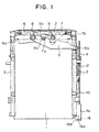
- FIG. 1 is a plan view showing the state that an IC card is loaded on an IC card connector device according to an embodiment of the present invention
- FIG. 2 is a plan view showing the state that the IC card is removed from the connector device
- FIG. 3 is a plan view of an eject mechanism
- FIG. 4 is an exploded perspective view of the eject mechanism
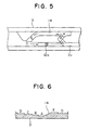
- FIG. 5 is a view describing a heart-shaped cam groove
- FIG. 6 is an folded view showing the cam surfaces of the heart-shaped cam groove
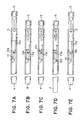
- FIG. 7 is a view describing an operation of the eject mechanism.
- the IC card connector device mainly comprises a pin housing 2 to which a multiplicity of pin contacts (none of them are shown) are inserted under pressure and fixed in a predetermined arrangement so that the socket contacts in an IC card 1 are connected thereto, a pair of frames 3 fixed to both the right and left sides of the pin housing 2 for guiding the IC card 1 from both the sides in the width direction thereof when it is inserted or withdrawn, a push rod 4 attached to one of the frames 3, an eject arm 5 turnably supported by the pin housing 2, first and second turning arms 6, 7 and the like and an eject mechanism which will be described later is interposed between the push rod 4 and the eject arm 5.
- a first support shaft 8 and a second support shaft 9 are provided with the pin housing 2 with a specific interval defined therebetween and an end of the eject arm 5 is turnably supported by the first support shaft 8.
- a coupling hole 5a and an engaging portion 5b are formed to the eject arm 5 and the engaging portion 5b projects to the outside of the frame 3.
- the first turning arm 6 is also turnably supported by the first support shaft 8 and a claw piece 6a for pushing out the IC card 1 and a tongue piece 6b projecting into the coupling hole 5a of the eject arm 5 are formed to the first turning arm 6.
- the second turning arm 7 is turnably supported by the second support shaft 9 and a claw piece 7a for pushing out the IC card 1 and a tongue piece 7b projecting into the coupling hole 5a of the eject arm 5 are formed to the second turning arm 7.
- the arrangement of the eject mechanism will be described below in detail based on FIG. 3 to FIG. 6.
- the IC card connector device shown in the embodiment which can be loaded with the two IC cards 1 along the upper and lower two-level guide grooves 3a formed to the inside surfaces of both the frames 3, is provided with the two push rods 4 for discharging both the IC cards 1.
- both the push rods 4 have fundamentally the same function and arrangement, one of the push rods 4 and the eject mechanism thereof will be described below. (FIG. 4 shows only one of the eject mechanisms.)
- the push rod 4 has a knob 4a at an end and is held so that it can be reciprocated by a projection 3b disposed to the outside surface of one of the frames 3 in the direction where the IC card 1 is inserted and withdrawn (the directions of arrows i, ii in FIG. 3).
- a lock lever 16 as check means is held in the knob 4a so that it can slide in the directions of arrows iii, iv in FIG. 3.
- the lock lever 16 is formed to an L-shape and a one end 16a is exposed to the front surface of the knob 4a.
- a transmission pin 12 having an L-shaped actuating portion 12a at an extreme end is swingably supported by the hole 4c of the push rod 4 at the other end and urged in the direction of the outside surface of the frame 3 by a leaf spring 13 locked to the push rod 4.
- a heart-shaped cam groove 14 is engraved to the outside surface of the frame 3 and the actuating portion 12a of the transmission pin 12 is engaged with the cam groove 14.
- the cam groove 14 has a plurality of cam surfaces A to E having a different height and the actuating portion 12a of the transmission pin 12 traces the cam surfaces A to E in the direction of arrows in FIG. 5.
- a drive plate 15 is held on the outside surface of the frame 3 so that it can reciprocate along the direction where the IC card 1 is inserted and withdrawn and a receiving portion 15a formed by being bent from the drive plate 15 is inserted into a slot 3c engraved to the outside surface of the frame 3.
- the slot 3c linearly continues to the cam surface D of the cam groove 14 and the receiving portion 15a of the drive plate 15 reciprocates between the slot 3c and the cam surface D. Further, an engaging hole 15b is formed to the drive plate 15 and the engaging hole 5b of the eject arm 5 passes through the frame 3 and is engaged with the engaging hole 15b of the drive plate 15.
- the push rod 4 When the connector device arranged as described above is not loaded with the IC card 1, the push rod 4 is pushed in the direction of the arrow i of FIG. 3 and held at a push position in the drawing. At the time, the actuating portion 12a of the transmission pin 12 is locked to the cam surface B of the cam groove 14 as shown in FIG. 7A and the push rod 4 is stably held at the push position by the tensile strength of the coil spring 10 and the transmission pin 12 locked to the cam surface B.
- the IC card 1 moving toward the pin housing 2 causes the pin contacts of the pin housing 2 to be inserted into the socket contacts thereof under pressure while pushing the claw pieces 6a, 7a of the first and second turning arms 6, 7.
- the insertion of the IC card 1 in a specific amount finishes the loading thereof with the secure connection of the IC card 1 to the respective contact pins (refer to FIG. 1).
- the one end 16a of the lock lever 16 is slid from the position of the arrow iii in the direction of the arrow iv and the other end 16b of the lock lever 16 is retracted into the knob 4a. Since the lock lever 16 is released from the locked state by the operation, when the knob 4a is pushed in the direction of the arrow i of FIG. 3, the push rod 4 is further moved forward from the push position.
- the actuating portion 12a of the transmission pin 12 is moved from the cam surface B of the cam groove 14 to the cam surface A and from the cam surface A to the cam surface D through the cam surface E by the tensile strength of the coil spring 10 as shown in FIG. 7C, the push rod 4 is moved in the direction of the arrow ii of FIG. 3 as shown in FIG. 7D and projected to the projecting position as shown in FIG. 2.
- the actuating portion 12a of the transmission pin 12 is not abutted against the receiving portion 15a of the drive plate 15 also at the time.
- the actuating portion 12a confronts the receiving portion 15a on the cam surface D.
- the actuating portion 12a of the transmission pin 12 is abutted against the receiving portion 15a of the drive plate 15 and presses it in the process that the actuating portion 12a moves to the cam surface D
- the eject arm 5 engaged with the drive plate 15 is turned and the claw pieces 6a, 7a of the first and second turning arms 6, 7 press both the ends of the front surface of the IC card 1 approximately linearly in a separating direction in accordance with the turn of the eject arm 5. Therefore, the socket contacts of the IC card 1 inserted into the contact pins of the pin housing 2 under pressure are released therefrom as shown by a two-dot-and-dash-line in FIG. 2. Consequently, the IC card 1 can be simply discharged from the IC card connector device by pulling out it while taking the operator's side thereof with fingers.
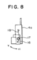
- a lock lever 16 is held by a the knob 4a so that it is turned in the directions of arrows v, vi about a support shaft 17 and the lock lever 16 executes a turning motion in place of a sliding motion.
- the lock lever 16 is always elastically urged in a locking direction (the direction of the arrow vi) and the locked state thereof is released only when it is turned in the direction of the arrow v against the elastic urging force of a spring 18. Since the employment of the above arrangement permits the push rod 4 to be automatically locked at the push position without the need of especially actuating the lock lever 16, the IC card 1 can be more securely prevented from being erroneously discharged. This arrangement may be applied to the lock lever 16 which executes the sliding motion.
- the present invention is also applicable to a connector device on which one or three or more IC cards can be loaded likewise.
- the check means for locking the movement of the push rod or releasing the lock of the push rod at the push position of the push rod is provided with the IC card connector device which includes the frames for supporting an IC card so that it can be inserted and withdrawn and the push rod capable of reciprocating between the push position and the projecting position and in which when the IC card is inserted, the push rod is located at the push position, the push rod is moved to the projecting position in this state by the first push motion of the push rod and the IC card is discharged by the second push motion of the push rod executed at this projecting position.
- the transmission pin capable of holding the push rod at the two positions or the push position and the projecting position and the heart-shaped cam mechanism composed of the heart-shaped cam groove are provided and the push rod is locked at the push position by the check means, the discharge of the IC card against the operator's intention can be prevented. Since the transmission pin is caused to trace the heart-shaped cam groove in one direction by the first push motion of the push rod in the state that locking motion performed by the check means at the push position is released to thereby permit the push rod to reciprocate between the push position and the projecting position, the IC card which has been inserted can be discharged by the second push motion of the push rod from the projecting position to the push position.
- the eject mechanism can be intensively disposed to the outside surface of the frame and the push rod, the size of the eject mechanism can be reduced and, in particular, it can be preferably applied to an IC card connector device corresponding to a plurality of IC cards.
- the check means when the check means is arranged to automatically lock the push rod at the time it is pushed, the check means can more securely prevent the erroneously discharge of the IC card.
- the check means can be composed of a lock lever which is slid or turned, and when the lock lever is attached to the push rod at the time, the check means can be integrally arranged with the push rod and the size of them can be reduced as a whole.
- operability of the check means when it performs locking and lock releasing operations can be improved.
Landscapes
- Engineering & Computer Science (AREA)
- Physics & Mathematics (AREA)
- General Physics & Mathematics (AREA)
- Theoretical Computer Science (AREA)
- Artificial Intelligence (AREA)
- Computer Vision & Pattern Recognition (AREA)
- Coupling Device And Connection With Printed Circuit (AREA)
- Details Of Connecting Devices For Male And Female Coupling (AREA)
Description
- The present invention relates to an IC card connector device provided with equipment which is used by inserting and withdrawing an IC card thereinto and therefrom, and more specifically, to an eject mechanism for discharging a loaded IC card.
- Usually, IC card connector devices are schematically arranged such that they include a pin header unit in which a multiplicity of pin contacts to be connected to socket contacts in an IC card are disposed in a housing, frames for guiding the IC card when it is inserted or withdrawn, an eject mechanism for releasing the loaded IC card from the pin contacts, and the like. There are also known IC card connector devices which include a pin housing formed integrally with frames.
- Conventionally, widely employed eject mechanisms are composed of a push rod held on the outside surface of a frame so as to reciprocate in the insertion/withdrawal direction of an IC card and an eject lever turnably supported by the frame or a pin housing with an end of the eject lever engaged with the push rod. When the push rod is pushed in an IC card connector device provided with this type of the eject mechanism in the state that the IC card is loaded, since the claw portion of the eject lever which turns in association with the push rod presses the IC card toward the operator's side, the operator can simply draw out the IC card with his fingers. However, this arrangement has such a drawback that since the push rod projects toward the operator's side in the state that the IC card is loaded, the IC card is discharged against the operator's intention by the erroneous operation of the projecting push rod.
- Whereas, the IC card connector device disclosed in Japanese Unexamined Utility Model Publication No. 6-13072 comprises first and second transmission levers which couple a push rod with a slide plate through a link, a third transmission lever which is turnably supported by the first transmission lever and engaged with and disengaged from the second transmission lever and a heart-shaped cam mechanism which can hold the push rod at a push position and a first projecting position so that the push force of the push rod can be selectively transmitted to the slide plate in accordance with a projecting amount of the push rod. That is, when an IC card is loaded, the push rod is held at the push position and the third transmission lever is not engaged with the second transmission lever. However, when the push rod is projected up to the first projecting position by the heart-shaped cam mechanism and thereafter it is further pulled to a second projecting position on the operator's side, the third transmission lever is engaged with the second transmission lever at the second projecting position. Thus, when the push rod is pressed in the direction of the push position in this state, the press force is transmitted to the slide plate through the respective transmission levers so that the slide plate presses the IC card to the operator's side. Therefore, the IC card can be prevented from being discharged against the operator's intention in such a manner that the push rod is held at the push position while the IC card is connected and projected up to the push position only when the IC card is discharged.
- As described above, according to the IC card connector device disclosed in the above publication, since the push rod is held at the push position while the IC card is connected and projected only when the IC card is discharged, the IC card can be prevented from being discharged against the operator's intention. Further, when the push rod is erroneously projected regardless of that the operator does not desire to discharge the IC card, the push rod can be held at the push position again without discharging the IC card by pushing the push rod from the first projecting position without pulling out it up to the second projecting position, whereby the operability of eject operation can be improved.
- However, there is a problem that since the three transmission levers coupled with each other through the link are interposed between the push rod and the slide plate and the press force of the push rod is transmitted to or shut off from the slide plate in accordance with the attitude of the respective transmission levers, a large space is necessary to turn the respective transmission levers and the miniaturization of the IC card connector device is prevented by it. Since the respective transmission levers must be inevitably disposed to the top surface or bottom surface of an IC card insertion port because of the above reasons, and in particular, since a plurality of sets of the respective transmission levers must be disposed in a vertically piled state by securing a sufficient space in an IC card connector device which permits at least two IC cards to be inserted thereinto and withdrawn therefrom, there is caused a problem that the size of the IC card connector device is increased in a height direction. Further, the IC card connector device has a problem that eject operation is troublesome because it requires to perform operation three times in ordinary eject operation, that is, operation for projecting the push rod held at the push position up to the first projecting position, operation for pulling out the push rod located at the first projecting position up to the second projecting position and operation for pushing the push rod projected to the second projecting position to the push position. Further, there still remains a problem that when the push rod is erroneously projected up to the second projecting position, the IC card is discharged against the operator's intention.
- The present invention is arranged such that check means is provided with a push rod capable of reciprocating between a push position and a projecting position for locking the push rod at the push position or releasing the lock of the push rod. After the push rod is projected from the push position to the projecting position by releasing the lock thereof, an IC card is discharged in the process that the push rod is moved from the projecting position to the push position again. With this operation, when it is not desired to discharge the IC card which has been inserted, the discharge operation of the IC card is prohibited by locking the push rod at the push position by the check means. Thus, a drawback that the IC card is discharged against the operator's intention can be overcome.
- US-A -5 846 096 against which appended claim 1 is delimited discloses an IC card connector device in which a push rod is moved to a projecting position by a first pressing operation via a cam groove. Subsequently, a second pressing operation acting upon an eject lever causes the IC card to be ejected.
- Furthermore, WO-A-95/14317 discloses a connector in which an IC card is ejected through the sliding movement of a push rod. This document, however, merely provides a connector in which only a forward movement of the push rod is locked.
- According to the present invention, an IC card connector device includes frames for supporting an IC card so that it can be inserted and withdrawn and a push rod capable of reciprocating between a push position and a projecting position, in which when the IC card is inserted, the push rod is located at the push position, the push rod is moved to the projecting position in this state by the first push motion of the push rod and the IC card is discharged by the second push motion of the push rod executed at the projecting position; characterised in that the IC card connector device comprises check means for locking the movement of the push rod or releasing the lock of the push rod at the push position, the check means being adapted so as to not hinder the movement of the push road when moving from the push position to the projecting position.
- With this arrangement, when it is not desired to discharge the IC card which has been inserted, the discharge operation of the IC card is prohibited by locking the push rod at the push position by the check means. Thus, a drawback that the IC card is discharged against the operator's intention can be overcome.
- By providing a transmission pin capable of holding the push rod at the two positions or the push position and the projecting position and a heart-shaped cam mechanism composed of a heart-shaped cam groove and the push rod is locked at the push position by the check means, it can be prevented that the IC card is discharged against the operator's intention. On the other hand, since a transmission pin is caused to trace a heart-shaped cam groove in one direction by the first push motion of the push rod in the state that the lock of the push rod is released by the check means at the push position and can reciprocate between the push position and the projecting position, the IC card which has been inserted can be discharged by the second push motion of the push rod from the projecting position to the push position. Further, since the eject mechanism can be intensively disposed to the outside surface of the frame and the push rod, the size of the eject mechanism can be reduced and, in particular, it can be preferably applied to an IC card connector device corresponding to a plurality of IC cards.
- Any check means may be used as the above check means so long as it can selectively permit the first push motion of the push rod and the check means may be mounted to the side of, for example, a personal computer main body or the like where the IC card connector device is attached.
- The check means can lock the push rod or release the lock thereof when it is manually actuated. When the check means is arranged to automatically lock the push rod at the time it is pushed, the check means can more securely prevent the erroneous discharge of the IC card.
- The check means can be composed of a lock lever which is slid or turned, and when the lock lever is attached to the push rod at the time, the check means can be integrally arranged with the push rod and the size thereof can be reduced. In particular, when a knob is attached to the push rod and the lock lever is disposed in the knob, operability of the check means can be improved when it performs locking and lock releasing operations.
- Embodiments of the invention will now be described, by way of example only, with reference to the accompanying drawings, in which:
- FIG. 1 is a plan view showing the state that an IC card is loaded on an IC card connector device according to an embodiment of the present invention;
- FIG. 2 is a plan view showing the state that the IC card is removed from the connector device;
- FIG. 3 is a plan view of an ejection mechanism provided with the connector device;
- FIG. 4 is an exploded perspective view of the eject mechanism;
- FIG. 5 is a view describing a heart-shaped cam groove;
- FIG. 6 is an folded view showing the cam surfaces of the heart-shaped cam groove;
- FIG. 7 is a view describing an operation of the eject mechanism of FIG. 3; and
- FIG. 8 is a view describing a modification of a lock lever.
-
- An embodiment will be described with reference to drawings. FIG. 1 is a plan view showing the state that an IC card is loaded on an IC card connector device according to an embodiment of the present invention, FIG. 2 is a plan view showing the state that the IC card is removed from the connector device, FIG. 3 is a plan view of an eject mechanism, FIG. 4 is an exploded perspective view of the eject mechanism, FIG. 5 is a view describing a heart-shaped cam groove, FIG. 6 is an folded view showing the cam surfaces of the heart-shaped cam groove, and FIG. 7 is a view describing an operation of the eject mechanism.
- As shown in FIG. 1 and FIG. 2, the IC card connector device according to the embodiment mainly comprises a
pin housing 2 to which a multiplicity of pin contacts (none of them are shown) are inserted under pressure and fixed in a predetermined arrangement so that the socket contacts in an IC card 1 are connected thereto, a pair offrames 3 fixed to both the right and left sides of thepin housing 2 for guiding the IC card 1 from both the sides in the width direction thereof when it is inserted or withdrawn, apush rod 4 attached to one of theframes 3, aneject arm 5 turnably supported by thepin housing 2, first and second turningarms push rod 4 and theeject arm 5. - A
first support shaft 8 and asecond support shaft 9 are provided with thepin housing 2 with a specific interval defined therebetween and an end of theeject arm 5 is turnably supported by thefirst support shaft 8. A coupling hole 5a and anengaging portion 5b are formed to theeject arm 5 and theengaging portion 5b projects to the outside of theframe 3. Thefirst turning arm 6 is also turnably supported by thefirst support shaft 8 and a claw piece 6a for pushing out the IC card 1 and atongue piece 6b projecting into the coupling hole 5a of theeject arm 5 are formed to thefirst turning arm 6. Thesecond turning arm 7 is turnably supported by thesecond support shaft 9 and a claw piece 7a for pushing out the IC card 1 and a tongue piece 7b projecting into the coupling hole 5a of theeject arm 5 are formed to thesecond turning arm 7. - The arrangement of the eject mechanism will be described below in detail based on FIG. 3 to FIG. 6. The IC card connector device shown in the embodiment, which can be loaded with the two IC cards 1 along the upper and lower two-level guide grooves 3a formed to the inside surfaces of both the
frames 3, is provided with the twopush rods 4 for discharging both the IC cards 1. However, since both thepush rods 4 have fundamentally the same function and arrangement, one of thepush rods 4 and the eject mechanism thereof will be described below. (FIG. 4 shows only one of the eject mechanisms.) - The
push rod 4 has a knob 4a at an end and is held so that it can be reciprocated by aprojection 3b disposed to the outside surface of one of theframes 3 in the direction where the IC card 1 is inserted and withdrawn (the directions of arrows i, ii in FIG. 3). Alock lever 16 as check means is held in the knob 4a so that it can slide in the directions of arrows iii, iv in FIG. 3. Thelock lever 16 is formed to an L-shape and a one end 16a is exposed to the front surface of the knob 4a. Although thepush rod 4 is always urged in the direction where the IC card 1 is inserted and withdrawn (the direction of the arrow ii of FIG. 3) by acoil spring 10, an amount of movement of thepush rod 4 in the direction is regulated to a projecting position of FIG. 3 by astopper piece 4b which is abutted against a mounting fitting 11 secured to theframe 3. Atransmission pin 12 having an L-shaped actuatingportion 12a at an extreme end is swingably supported by the hole 4c of thepush rod 4 at the other end and urged in the direction of the outside surface of theframe 3 by aleaf spring 13 locked to thepush rod 4. - A heart-
shaped cam groove 14 is engraved to the outside surface of theframe 3 and the actuatingportion 12a of thetransmission pin 12 is engaged with thecam groove 14. As shown in FIG. 5 and FIG. 6, thecam groove 14 has a plurality of cam surfaces A to E having a different height and the actuatingportion 12a of thetransmission pin 12 traces the cam surfaces A to E in the direction of arrows in FIG. 5. Adrive plate 15 is held on the outside surface of theframe 3 so that it can reciprocate along the direction where the IC card 1 is inserted and withdrawn and a receivingportion 15a formed by being bent from thedrive plate 15 is inserted into aslot 3c engraved to the outside surface of theframe 3. Theslot 3c linearly continues to the cam surface D of thecam groove 14 and thereceiving portion 15a of thedrive plate 15 reciprocates between theslot 3c and the cam surface D. Further, anengaging hole 15b is formed to thedrive plate 15 and theengaging hole 5b of theeject arm 5 passes through theframe 3 and is engaged with theengaging hole 15b of thedrive plate 15. - When the connector device arranged as described above is not loaded with the IC card 1, the
push rod 4 is pushed in the direction of the arrow i of FIG. 3 and held at a push position in the drawing. At the time, the actuatingportion 12a of thetransmission pin 12 is locked to the cam surface B of thecam groove 14 as shown in FIG. 7A and thepush rod 4 is stably held at the push position by the tensile strength of thecoil spring 10 and thetransmission pin 12 locked to the cam surface B. - When the IC card 1 is being inserted along the guide groove 3a of the
frame 3, the IC card 1 moving toward thepin housing 2 causes the pin contacts of thepin housing 2 to be inserted into the socket contacts thereof under pressure while pushing the claw pieces 6a, 7a of the first and second turningarms first turning arm 6 and thesecond turning arm 7 turn in an opposite direction each other using thefirst support shaft 8 and thesecond support shaft 9 as their axis of turn, respectively and the turn of the turningarms eject arm 5 through the portion where thetongue pieces 6b, 7b are coupled with the coupling hole 5a, theeject arm 5 turns using thefirst support shaft 8 as its axis of turn and thedrive plate 15 moves toward the operator's side of theframe 3 in association with the turn. With this operation, although the receivingportion 15a of thedrive plate 15 moves from theslot 3c to the cam surface D of thecam groove 14 as shown in FIG. 7B, since theactuating portion 12a of thetransmission pin 12 is locked to the cam surface B, the receivingportion 15a is not abutted against the actuatingportion 12a. Thus, thepush rod 4 is maintained in the state that it is held at the push position while the IC card 1 is connected. - When the IC card 1 is to be maintained in its loaded state after it is loaded, the one end 16a of the
lock lever 16 exposed to the front surface of the knob 4a is slid in the direction of the arrow iii in FIG. 3 and theother end 16b of thelock lever 16 is projected from a side of the knob 4a. As a result, theother end 16b of thelock lever 16 enters between the front surface of theframe 3 and the rear surface of the knob 4a as shown in FIG. 1 and locks thepush rod 4 so that it cannot be further pushed from the push position. Thus, even if the knob 4a is erroneously pressed, thepush rod 4 is not moved and the IC card 1 is maintained in the connected state. - On the other hand, when the IC card 1 is to be discharged from the connector device, first, the one end 16a of the
lock lever 16 is slid from the position of the arrow iii in the direction of the arrow iv and theother end 16b of thelock lever 16 is retracted into the knob 4a. Since thelock lever 16 is released from the locked state by the operation, when the knob 4a is pushed in the direction of the arrow i of FIG. 3, thepush rod 4 is further moved forward from the push position. As a result, since theactuating portion 12a of thetransmission pin 12 is moved from the cam surface B of thecam groove 14 to the cam surface A and from the cam surface A to the cam surface D through the cam surface E by the tensile strength of thecoil spring 10 as shown in FIG. 7C, thepush rod 4 is moved in the direction of the arrow ii of FIG. 3 as shown in FIG. 7D and projected to the projecting position as shown in FIG. 2. The actuatingportion 12a of thetransmission pin 12 is not abutted against the receivingportion 15a of thedrive plate 15 also at the time. Thus, when thepush rod 4 is moved to the projecting position, the actuatingportion 12a confronts the receivingportion 15a on the cam surface D. - When the knob 4a of the
push rod 4 is pushed again in the direction of the arrow i of FIG. 3 after it is projected up to the projecting position as described above, since theactuating portion 12a of thetransmission pin 12 is locked to the cam surface B of thecam groove 14 from the cam surface D through the cam surface C as shown in FIG. 7E. Thepush rod 4 is held at the push position again. At the time, since theactuating portion 12a of thetransmission pin 12 is abutted against the receivingportion 15a of thedrive plate 15 and presses it in the process that theactuating portion 12a moves to the cam surface D, theeject arm 5 engaged with thedrive plate 15 is turned and the claw pieces 6a, 7a of the first and second turningarms eject arm 5. Therefore, the socket contacts of the IC card 1 inserted into the contact pins of thepin housing 2 under pressure are released therefrom as shown by a two-dot-and-dash-line in FIG. 2. Consequently, the IC card 1 can be simply discharged from the IC card connector device by pulling out it while taking the operator's side thereof with fingers. - In an embodiment shown in FIG. 8, a
lock lever 16 is held by a the knob 4a so that it is turned in the directions of arrows v, vi about asupport shaft 17 and thelock lever 16 executes a turning motion in place of a sliding motion. Thelock lever 16 is always elastically urged in a locking direction (the direction of the arrow vi) and the locked state thereof is released only when it is turned in the direction of the arrow v against the elastic urging force of aspring 18. Since the employment of the above arrangement permits thepush rod 4 to be automatically locked at the push position without the need of especially actuating thelock lever 16, the IC card 1 can be more securely prevented from being erroneously discharged. This arrangement may be applied to thelock lever 16 which executes the sliding motion. - Although the connector device on which two IC cards can be loaded are exemplified and described in the above respective embodiments, the present invention is also applicable to a connector device on which one or three or more IC cards can be loaded likewise.
- The present invention executed in the above embodiments can achieve the following advantages.
- The check means for locking the movement of the push rod or releasing the lock of the push rod at the push position of the push rod is provided with the IC card connector device which includes the frames for supporting an IC card so that it can be inserted and withdrawn and the push rod capable of reciprocating between the push position and the projecting position and in which when the IC card is inserted, the push rod is located at the push position, the push rod is moved to the projecting position in this state by the first push motion of the push rod and the IC card is discharged by the second push motion of the push rod executed at this projecting position. As a result, when it is not desired to discharge the IC card which has been inserted, the discharge operation of the IC card is prohibited by locking the push rod at the push position by the check means, whereby the drawback that the IC card is discharged against the operator's intention can be overcome.
- When the transmission pin capable of holding the push rod at the two positions or the push position and the projecting position and the heart-shaped cam mechanism composed of the heart-shaped cam groove are provided and the push rod is locked at the push position by the check means, the discharge of the IC card against the operator's intention can be prevented. Since the transmission pin is caused to trace the heart-shaped cam groove in one direction by the first push motion of the push rod in the state that locking motion performed by the check means at the push position is released to thereby permit the push rod to reciprocate between the push position and the projecting position, the IC card which has been inserted can be discharged by the second push motion of the push rod from the projecting position to the push position. Further, since the eject mechanism can be intensively disposed to the outside surface of the frame and the push rod, the size of the eject mechanism can be reduced and, in particular, it can be preferably applied to an IC card connector device corresponding to a plurality of IC cards.
- In addition, when the check means is arranged to automatically lock the push rod at the time it is pushed, the check means can more securely prevent the erroneously discharge of the IC card.
- The check means can be composed of a lock lever which is slid or turned, and when the lock lever is attached to the push rod at the time, the check means can be integrally arranged with the push rod and the size of them can be reduced as a whole. In particular, when the knob is attached to the push rod and the lock lever is disposed in the knob, operability of the check means when it performs locking and lock releasing operations can be improved.
Claims (7)
- An IC card connector device including frames (3) for supporting an IC card (1) so that it can be inserted and withdrawn, and a push rod (4) capable of reciprocating between a push position and a projecting position; wherein, upon insertion of the IC card, the push rod is located at a push position, the push rod being movable to the projecting position from the push position by a first push motion of the push rod, and the IC card being discharged by a second push motion of the push rod executed at the projecting position; characterised in that said IC card connector device comprises check means (16) disposed at the push rod for locking or releasing the movement of the push rod at the push position, the check means being adapted so as to not hinder the movement of the push rod when moving from the push position to the projecting position.
- An IC card connector device according to Claim 1, comprising a transmission pin (12) capable of holding the push rod at the two positions or the push position and the projecting position and a heart-shaped cam mechanism composed of a heart-shaped cam groove (14).
- An IC card connector device according to Claim 1 or 2, wherein said check means is manually actuated to thereby lock the push rod or release the lock of the push rod.
- An IC card connector device according to Claim 1 or 2, wherein said check means is automatically actuated when the push rod is pushed to thereby lock the push rod at the push position.
- An IC connector device according to Claim 1 or 2, wherein said check means is composed of a lock lever which is slid or turned.
- An IC card connector device according to Claim 5, wherein said lock lever is attached to the push rod.
- An IC card connector device according to Claim 6, wherein a knob (4a) is attached to the push rod and said lock lever is disposed in said knob.
Applications Claiming Priority (6)
| Application Number | Priority Date | Filing Date | Title |
|---|---|---|---|
| JP255393/97 | 1997-09-19 | ||
| JP25539397 | 1997-09-19 | ||
| JP25539397 | 1997-09-19 | ||
| JP342/98 | 1998-01-05 | ||
| JP10000342A JP2839242B1 (en) | 1997-09-19 | 1998-01-05 | Connector device for IC card |
| JP34298 | 1998-01-05 |
Publications (3)
| Publication Number | Publication Date |
|---|---|
| EP0903690A2 EP0903690A2 (en) | 1999-03-24 |
| EP0903690A3 EP0903690A3 (en) | 2000-03-29 |
| EP0903690B1 true EP0903690B1 (en) | 2004-07-07 |
Family
ID=26333307
Family Applications (1)
| Application Number | Title | Priority Date | Filing Date |
|---|---|---|---|
| EP98302424A Expired - Lifetime EP0903690B1 (en) | 1997-09-19 | 1998-03-30 | IC card connector device |
Country Status (6)
| Country | Link |
|---|---|
| US (1) | US6039587A (en) |
| EP (1) | EP0903690B1 (en) |
| JP (1) | JP2839242B1 (en) |
| KR (1) | KR100309044B1 (en) |
| DE (1) | DE69824929T2 (en) |
| SG (1) | SG72798A1 (en) |
Families Citing this family (19)
| Publication number | Priority date | Publication date | Assignee | Title |
|---|---|---|---|---|
| JP3297639B2 (en) * | 1998-01-28 | 2002-07-02 | ヒロセ電機株式会社 | Electrical connector for card |
| JP3701792B2 (en) * | 1998-04-10 | 2005-10-05 | アルプス電気株式会社 | Connector device |
| JP3673395B2 (en) * | 1998-04-10 | 2005-07-20 | アルプス電気株式会社 | Connector device |
| FR2793923B1 (en) * | 1999-05-17 | 2001-07-27 | Valeo Securite Habitacle | IMPROVED ARRANGEMENT FOR LONGITUDINAL LOCKING OF A RIGID DATA CARRIER IN A DATA EXCHANGE DEVICE |
| FR2793922B1 (en) * | 1999-05-17 | 2001-07-27 | Valeo Securite Habitacle | IMPROVED ARRANGEMENT FOR LONGITUDINAL LOCKING OF A RIGID DATA CARRIER IN A DATA EXCHANGE DEVICE |
| FR2793921B1 (en) | 1999-05-17 | 2001-06-29 | Itt Mfg Enterprises Inc | COMPACT ASSEMBLY FOR CONNECTING A CARD WITH AN INTEGRATED CIRCUIT (S) COMPRISING MEANS OF EJECTING THE CARD |
| JP4365977B2 (en) | 2000-03-10 | 2009-11-18 | モレックス インコーポレイテド | Card connector |
| JP4028231B2 (en) * | 2001-12-28 | 2007-12-26 | 日本圧着端子製造株式会社 | Card connector ejection mechanism |
| KR100668915B1 (en) * | 2002-11-11 | 2007-01-12 | 엘지전자 주식회사 | Multi Bay for Computer |
| JP2004055256A (en) * | 2002-07-18 | 2004-02-19 | Tyco Electronics Amp Kk | Connector for cards |
| JP3884343B2 (en) * | 2002-07-18 | 2007-02-21 | タイコエレクトロニクスアンプ株式会社 | Card connector assembly |
| US6881088B2 (en) * | 2003-07-29 | 2005-04-19 | Hon Hai Precision Ind. Co., Ltd. | Connector assembly with actuation system |
| TW200627724A (en) * | 2005-01-24 | 2006-08-01 | Top Yang Technology Entpr Co | Metallic sliding slot structure for an electrical connector |
| EP1830618A1 (en) * | 2005-06-21 | 2007-09-05 | Tyco Electronics AMP K.K. | Card connector |
| US8179630B2 (en) * | 2008-08-04 | 2012-05-15 | International Business Machines Corporation | Storage slot for portable data storage cartridges |
| TWM373054U (en) * | 2009-05-25 | 2010-01-21 | Hon Hai Prec Ind Co Ltd | Electrical card connector |
| US9837765B2 (en) | 2015-06-25 | 2017-12-05 | Microsoft Technology Licensing, Llc | Apparatus for ejecting at least one integrated circuit card |
| KR102344952B1 (en) | 2020-04-28 | 2021-12-30 | 주식회사 이노켐텍 | Electrolyzed water generation device |
| CN116169523A (en) * | 2022-12-13 | 2023-05-26 | 立讯汽车技术(上海)有限公司 | Mechanical lock and charging connector |
Family Cites Families (13)
| Publication number | Priority date | Publication date | Assignee | Title |
|---|---|---|---|---|
| JP2576064Y2 (en) * | 1992-03-06 | 1998-07-09 | バーグ・テクノロジー・インコーポレーテッド | Connector device |
| JP2761490B2 (en) * | 1993-01-21 | 1998-06-04 | モレックス インコーポレーテッド | Multiple fulcrum type eject mechanism in IC memory card insertion and holding device |
| US5836775A (en) * | 1993-05-13 | 1998-11-17 | Berg Tehnology, Inc. | Connector apparatus |
| US5451168A (en) * | 1993-10-01 | 1995-09-19 | Berg Technology, Inc. | Connector apparatus for memory cards having a one-piece integrated frame |
| JP3860230B2 (en) * | 1993-11-19 | 2006-12-20 | バーグ・テクノロジー・インコーポレーテッド | Data processing medium connector and data processing medium locking mechanism |
| US5443395A (en) * | 1994-06-08 | 1995-08-22 | Molex Incorporated | Ejector system for an IC card connector apparatus |
| JP3076498B2 (en) * | 1994-09-27 | 2000-08-14 | ヒロセ電機株式会社 | Electrical connector for PC card |
| JP2707061B2 (en) * | 1994-10-06 | 1998-01-28 | モレックス インコーポレーテッド | Card eject mechanism in card drive unit |
| US5667396A (en) * | 1995-08-08 | 1997-09-16 | Tongrand Limited | Memory card connector with card ejection mechanism |
| JP3209892B2 (en) * | 1995-09-06 | 2001-09-17 | アルプス電気株式会社 | PC card connector |
| JP3228456B2 (en) * | 1995-10-17 | 2001-11-12 | ヒロセ電機株式会社 | Electrical connector for PC card |
| JP3262491B2 (en) * | 1996-02-29 | 2002-03-04 | ヒロセ電機株式会社 | Electrical connector for card |
| US5655918A (en) * | 1996-02-29 | 1997-08-12 | Berg Technology, Inc. | Selectable ejector for a double-deck PCMCIA eject header |
-
1998
- 1998-01-05 JP JP10000342A patent/JP2839242B1/en not_active Expired - Fee Related
- 1998-03-25 SG SG1998000622A patent/SG72798A1/en unknown
- 1998-03-30 EP EP98302424A patent/EP0903690B1/en not_active Expired - Lifetime
- 1998-03-30 DE DE69824929T patent/DE69824929T2/en not_active Expired - Fee Related
- 1998-03-31 KR KR1019980011291A patent/KR100309044B1/en not_active Expired - Fee Related
- 1998-09-18 US US09/156,990 patent/US6039587A/en not_active Expired - Fee Related
Also Published As
| Publication number | Publication date |
|---|---|
| JP2839242B1 (en) | 1998-12-16 |
| SG72798A1 (en) | 2000-05-23 |
| KR19990029148A (en) | 1999-04-26 |
| DE69824929T2 (en) | 2005-07-14 |
| US6039587A (en) | 2000-03-21 |
| KR100309044B1 (en) | 2001-11-17 |
| EP0903690A2 (en) | 1999-03-24 |
| EP0903690A3 (en) | 2000-03-29 |
| DE69824929D1 (en) | 2004-08-12 |
| JPH11154561A (en) | 1999-06-08 |
Similar Documents
| Publication | Publication Date | Title |
|---|---|---|
| EP0903690B1 (en) | IC card connector device | |
| US6113403A (en) | Connector device | |
| EP0883079B1 (en) | Connector device for IC card | |
| US6095835A (en) | IC card connector device with eject mechanism for ejecting IC card | |
| US5179505A (en) | Ejector for memory card | |
| EP0438914A1 (en) | IC card ejecting device | |
| US6934159B2 (en) | Card connector | |
| JP3556090B2 (en) | Connector device for IC card | |
| US5984702A (en) | Apparatus for ejecting an integrated circuit card from an electronic device | |
| US5653603A (en) | Card eject mechanism for card-receiving connector | |
| KR100344504B1 (en) | Information processing medium connector with locking means | |
| US6036514A (en) | Connector device for IC card | |
| US6042403A (en) | Connector device for IC card | |
| JP3450995B2 (en) | Connector device for IC card | |
| US6033244A (en) | Connector device for IC card | |
| TW457748B (en) | Connector device for IC card | |
| TW390052B (en) | IC card connector device | |
| JP2001291069A (en) | Card fetching structure for card processor | |
| JP2001291068A (en) | Card restraining structure for card processor | |
| JP2001291061A (en) | Card processor |
Legal Events
| Date | Code | Title | Description |
|---|---|---|---|
| PUAI | Public reference made under article 153(3) epc to a published international application that has entered the european phase |
Free format text: ORIGINAL CODE: 0009012 |
|
| AK | Designated contracting states |
Kind code of ref document: A2 Designated state(s): DE GB |
|
| AX | Request for extension of the european patent |
Free format text: AL;LT;LV;MK;RO;SI |
|
| PUAL | Search report despatched |
Free format text: ORIGINAL CODE: 0009013 |
|
| AK | Designated contracting states |
Kind code of ref document: A3 Designated state(s): AT BE CH DE DK ES FI FR GB GR IE IT LI LU MC NL PT SE |
|
| AX | Request for extension of the european patent |
Free format text: AL;LT;LV;MK;RO;SI |
|
| 17P | Request for examination filed |
Effective date: 20000413 |
|
| AKX | Designation fees paid |
Free format text: DE GB |
|
| 17Q | First examination report despatched |
Effective date: 20030424 |
|
| RTI1 | Title (correction) |
Free format text: IC CARD CONNECTOR DEVICE |
|
| GRAP | Despatch of communication of intention to grant a patent |
Free format text: ORIGINAL CODE: EPIDOSNIGR1 |
|
| GRAP | Despatch of communication of intention to grant a patent |
Free format text: ORIGINAL CODE: EPIDOSNIGR1 |
|
| GRAS | Grant fee paid |
Free format text: ORIGINAL CODE: EPIDOSNIGR3 |
|
| GRAA | (expected) grant |
Free format text: ORIGINAL CODE: 0009210 |
|
| AK | Designated contracting states |
Kind code of ref document: B1 Designated state(s): DE GB |
|
| REG | Reference to a national code |
Ref country code: GB Ref legal event code: FG4D |
|
| REF | Corresponds to: |
Ref document number: 69824929 Country of ref document: DE Date of ref document: 20040812 Kind code of ref document: P |
|
| PGFP | Annual fee paid to national office [announced via postgrant information from national office to epo] |
Ref country code: GB Payment date: 20050223 Year of fee payment: 8 |
|
| PLBE | No opposition filed within time limit |
Free format text: ORIGINAL CODE: 0009261 |
|
| STAA | Information on the status of an ep patent application or granted ep patent |
Free format text: STATUS: NO OPPOSITION FILED WITHIN TIME LIMIT |
|
| PGFP | Annual fee paid to national office [announced via postgrant information from national office to epo] |
Ref country code: DE Payment date: 20050524 Year of fee payment: 8 |
|
| 26N | No opposition filed |
Effective date: 20050408 |
|
| PG25 | Lapsed in a contracting state [announced via postgrant information from national office to epo] |
Ref country code: GB Free format text: LAPSE BECAUSE OF NON-PAYMENT OF DUE FEES Effective date: 20060330 |
|
| PG25 | Lapsed in a contracting state [announced via postgrant information from national office to epo] |
Ref country code: DE Free format text: LAPSE BECAUSE OF NON-PAYMENT OF DUE FEES Effective date: 20061003 |
|
| GBPC | Gb: european patent ceased through non-payment of renewal fee |
Effective date: 20060330 |