EP0903686B1 - Apparatus for issuing wireless information storage media - Google Patents
Apparatus for issuing wireless information storage media Download PDFInfo
- Publication number
- EP0903686B1 EP0903686B1 EP98116207A EP98116207A EP0903686B1 EP 0903686 B1 EP0903686 B1 EP 0903686B1 EP 98116207 A EP98116207 A EP 98116207A EP 98116207 A EP98116207 A EP 98116207A EP 0903686 B1 EP0903686 B1 EP 0903686B1
- Authority
- EP
- European Patent Office
- Prior art keywords
- information
- wireless
- information storage
- memory section
- storage medium
- Prior art date
- Legal status (The legal status is an assumption and is not a legal conclusion. Google has not performed a legal analysis and makes no representation as to the accuracy of the status listed.)
- Expired - Lifetime
Links
Images


Classifications
-
- G—PHYSICS
- G06—COMPUTING OR CALCULATING; COUNTING
- G06K—GRAPHICAL DATA READING; PRESENTATION OF DATA; RECORD CARRIERS; HANDLING RECORD CARRIERS
- G06K17/00—Methods or arrangements for effecting co-operative working between equipments covered by two or more of main groups G06K1/00 - G06K15/00, e.g. automatic card files incorporating conveying and reading operations
- G06K17/0022—Methods or arrangements for effecting co-operative working between equipments covered by two or more of main groups G06K1/00 - G06K15/00, e.g. automatic card files incorporating conveying and reading operations arrangements or provisions for transferring data to distant stations, e.g. from a sensing device
- G06K17/0025—Methods or arrangements for effecting co-operative working between equipments covered by two or more of main groups G06K1/00 - G06K15/00, e.g. automatic card files incorporating conveying and reading operations arrangements or provisions for transferring data to distant stations, e.g. from a sensing device the arrangement consisting of a wireless interrogation device in combination with a device for optically marking the record carrier
-
- G—PHYSICS
- G06—COMPUTING OR CALCULATING; COUNTING
- G06K—GRAPHICAL DATA READING; PRESENTATION OF DATA; RECORD CARRIERS; HANDLING RECORD CARRIERS
- G06K1/00—Methods or arrangements for marking the record carrier in digital fashion
- G06K1/12—Methods or arrangements for marking the record carrier in digital fashion otherwise than by punching
- G06K1/121—Methods or arrangements for marking the record carrier in digital fashion otherwise than by punching by printing code marks
-
- G—PHYSICS
- G06—COMPUTING OR CALCULATING; COUNTING
- G06K—GRAPHICAL DATA READING; PRESENTATION OF DATA; RECORD CARRIERS; HANDLING RECORD CARRIERS
- G06K19/00—Record carriers for use with machines and with at least a part designed to carry digital markings
- G06K19/06—Record carriers for use with machines and with at least a part designed to carry digital markings characterised by the kind of the digital marking, e.g. shape, nature, code
- G06K19/067—Record carriers with conductive marks, printed circuits or semiconductor circuit elements, e.g. credit or identity cards also with resonating or responding marks without active components
- G06K19/07—Record carriers with conductive marks, printed circuits or semiconductor circuit elements, e.g. credit or identity cards also with resonating or responding marks without active components with integrated circuit chips
- G06K19/077—Constructional details, e.g. mounting of circuits in the carrier
- G06K19/07749—Constructional details, e.g. mounting of circuits in the carrier the record carrier being capable of non-contact communication, e.g. constructional details of the antenna of a non-contact smart card
-
- G—PHYSICS
- G06—COMPUTING OR CALCULATING; COUNTING
- G06K—GRAPHICAL DATA READING; PRESENTATION OF DATA; RECORD CARRIERS; HANDLING RECORD CARRIERS
- G06K19/00—Record carriers for use with machines and with at least a part designed to carry digital markings
- G06K19/06—Record carriers for use with machines and with at least a part designed to carry digital markings characterised by the kind of the digital marking, e.g. shape, nature, code
- G06K19/08—Record carriers for use with machines and with at least a part designed to carry digital markings characterised by the kind of the digital marking, e.g. shape, nature, code using markings of different kinds or more than one marking of the same kind in the same record carrier, e.g. one marking being sensed by optical and the other by magnetic means
- G06K19/10—Record carriers for use with machines and with at least a part designed to carry digital markings characterised by the kind of the digital marking, e.g. shape, nature, code using markings of different kinds or more than one marking of the same kind in the same record carrier, e.g. one marking being sensed by optical and the other by magnetic means at least one kind of marking being used for authentication, e.g. of credit or identity cards
- G06K19/18—Constructional details
Definitions
- the present invention relates to an apparatus for issuing information storage media which media an adapted, e.g., to be attached to commodities or articles for processing them, and that information can be read from and written into by radio.
- next-generation information carrier attention has been paid to a wireless information storage medium which makes communications with outside by radio to read information from an internal storage device, such as an IC memory, or write information into the storage device.
- Such a wireless information storage medium has been attached as a wireless tag to commodities for the purpose of preventing shoplifting or employed as a ski lift ticket in ski grounds.
- an attempt has been made to incorporate the storage medium into a commuter's pass in a wireless automatic ticket inspecting system.
- a system employing such wireless information storage media allows predetermined processing to be performed in non-contact manner without the need of inserting them into a processing machine and thus provides convenience that conventional systems lack.
- Such a wireless information storage medium itself as a wireless tag, usually has no image display that persons can visually observe.
- Such a form of storage medium does not matter to a system in which there is no need of directly presenting information concerning commodities to persons (customers) as in a shoplifting preventive system.
- wireless tags are used as price tags and price information contained in tags attached to commodities a customer purchases can be read by radio, then accounting processing can be performed with only these tags. This will provide more efficient accounting processing than at present. In this case, however, it is required for customers to be able to confirm the prices of commodities themselves.
- Jpn. Pat. Appln. KOKAI Publication No. 4 - 368894 a noncontact recording medium which has a noncontact recording means built in and is provided on a surface with a rewritable visible information recording area consisting of a heat-reversible material. That is, a recording area which permits visible information to be recorded by heat in a rewritable manner is formed on the surface of a noncontact recording medium having noncontact recording means built in.
- wireless information storage media are suitable for people to carry but are relatively poor in flexibility. Thus, various restraints may arise in attaching them to articles for use as price tags, article tags, and manufacture process management tags.
- Jpn. Pat. Appln. KOKAI Publication No. 9 - 104189 discloses an information storage medium in which an electronic component as noncontact recording means is fixed to the surface of a paper-like base member and a printing medium is stuck on it to allow repeated printing of visible information.
- the information storage medium is good in flexibility, but a problem arises in that the electronic component is subject to break due to mechanical stress.
- a storage medium issuing apparatus for issuing the information storage medium, which is equipped with a writing/printing unit for writing and printing ID information into and onto an ID tag as an information storage medium.
- the writing/printing unit has a transmitter/receiver unit, an ID tag stacker, a printer, a feed mechanism for feeding ID tags to the printer, an eject mechanism for ejecting the ID tags after printing, a printer controller, and a main controller for controlling these components.
- the printer has printing means for printing information on ID tag rewritable paper and erasing means for erasing printed information.
- the transmitter/receiver unit has an antenna for make communications with the ID tag and a transmitter/receiver circuit for modulating and demodulating information.
- the main controller enters data to be written from a host computer through a host interface and controls the printer controller, the printer, and the transmitter/receiver unit for controlling the writing and printing of the ID information.
- the main controller has an MPU for such control and a memory for storing data to be written entered through the host interface.
- the issuing apparatus has means for deciding whether or not ID information has been recorded on an ID tag. If ID information has already been recorded, it is erased and then new ID information is written. The number of times ID information is written is handled as part of ID information. The number of write operations is printed or the ID information printed position is changed according to the number of write operations.
- the issuing apparatus In issuing a wireless information storage medium, the issuing apparatus arranged as described above performs writing of given information into the information storage unit and printing of visible information on the visible information recording area.
- a semiconductor circuit constituting the information storage unit is generally an IC or LSI component, it may be damaged by mechanical stress to lose its functions at the time of printing visible information.
- a thermal or mechanical stress may be imposed on the IC or LSI built into the information storage medium. Such a stress causes a wireless information storage medium that has no properly functioning semiconductor circuit to be issued, resulting in low yields.
- FIG. 1 which illustrates in sectional view an embodiment of a wireless information storage medium of the present invention
- a wireless information storage unit 2 on one side of a sheet-like base member 1 there are provided a wireless information storage unit 2 and an image (visible information) recording unit (area) 3.
- the base member may consist of plastic, such as polyethylene terephthalate or vinyl chloride resin, paper, such as wood free paper, or synthetic paper.
- a sheet of synthetic paper of about 60 ⁇ m in thickness is used.
- the wireless information storage unit 2 has a wireless information storage element and an antenna which are molded with a resin.
- the wireless information storage unit comprises a transmitting/receiving antenna 4 consisting of a loop coil and a wireless information storage element (LSI chip) 12 which are molded with a plastic into the form of a stand-alone component.
- LSI chip wireless information storage element
- the wireless information storage unit 2 is excellent in mechanical durability and high in reliability.
- the wireless information storage unit 2 measures 25 mm ⁇ 25 mm.
- FIG. 3 shows a circuit arrangement of the wireless information storage element 12, which is composed of a power generator 21, a clock generator 22, a demodulator 23, a modulator 24, a control logic 25, and a nonvolatile memory 26 as storage means.
- a modulated data signal sent from an external device and received by the antenna 4 is applied to the power generator 21 and the clock generator 22.
- the power generator rectifies the modulated data signal and smoothes the rectified output for supply power to each circuit component.
- the clock generator generates clock pulses from the modulated data signal for supply to each circuit component.
- the modulated data signal received is demodulated by the demodulator 23 and the resulting original data signal is then stored in the nonvolatile memory 26 under the control of the control logic 25.
- the image recording unit 3 use may be made of a rewritable recording layer, a thermosensible recording layer, or an ink-jet recording layer.
- the ink-jet recording layer is used.
- the image recording unit 3 is formed as follows: An ink accepting layer application liquid which is a mixture of an alumina sol containing a solid content of 18% synthesized from aluminum alkoxide and a solution containing a polyvinyl alcohol content of 6% by weight is applied to a sheet of synthetic paper in the form of a strip.
- the application is such that the applied width (the width of the image recording unit 3) is 60 mm, the non-applied width (the width of the base member 1 minus the applied width 3) is 30 mm, and the thickness after drying is 10 ⁇ m.
- the applied layer is dried to form a strip ink accepting layer (image recording unit).
- the wireless information storage units 2 are put on the non-applied area of the base member at intervals of 30 mm.
- the synthetic paper which is provided on top with a plurality of image recording units 3 and a plurality of wireless information storage units 2 is cut into pieces each having a wireless information storage unit and an ink accepting layer of 30 mm ⁇ 60 mm.
- the wireless information storage medium of this embodiment has a feature that a wireless information storage unit and an image recording unit are provided on the same base member.
- a wireless information storage medium can be realized which provides better flexibility than conventional ones and fits any article to which it is to be attached like a label.
- the wireless information storage unit and the image recording unit are provided on one side of a base member, its other side can be utilized for advertisement or as a message board. The other side can also be utilized for attachment to an article.
- an ink-jet recording layer as an image recording unit, an ink-jet recording system that does not subject the wireless information storage unit to mechanical stress can be used to print visual information.
- An image recording unit can also be formed on the wireless information storage unit.
- each of the wireless information storage unit and the image recording unit may be set arbitrarily. Further, in addition to the ink-jet recording unit, image recording units suitable for various recording systems, including thermal recording systems, rewritable recording systems, etc., can be used.
- FIG. 4 is a sectional view of a wireless information storage medium according to another embodiment.
- 31 denotes a sheet-like base member, which is provided at an end of its one side with a wireless information storage unit 32 and on its other side with an image recording unit 33.
- the wireless information storage unit 32 is identical in arrangement to the one 2 used in the previous embodiment and hence its description is omitted.
- the image recording unit 33 is composed of a rewritable recording layer 34 and a protective layer 35.
- the base member 36 may be made of plastic, such as polyethylene terephthalate (PET), vinyl chloride resin, or the like, or synthetic paper. When the image recording unit 33 is used a plurality of times, such a base member as has mechanical durability is preferably used.
- the thickness of the base member is set to less than 1 mm and preferably 10 to 500 ⁇ m. In this embodiment, a PET sheet of 188 ⁇ m in thickness is used as the base member.
- the recording layer may be made of a coloring rewritable recording material, a high molecular matrix/low molecular composite film material, a magnetic capsule recording material, or the like.
- An example of a coloring rewritable recording material is a leuco-dye-based rewritable recording material which is composed of a leuco dye and a reversible developer.
- a reversible developer there is a compound having decolorizer and a long chain alkyl group.
- the decolorizer is a compound having an acid region and a basis region within a molecule.
- examples of such materials include salts of phenol carboxylic acid and organic amine, complex salts of phenolic compound and organic amine, and organic amphoteric compounds.
- Such materials are disclosed in, for example, Jpn. Pat. Appln. KOKAI Publications Nos. 6 - 191150 and 6 - 191151.
- Examples of compounds having a long chain alkyl group with reversible development include ascorbic acid compounds having a long aliphatic alkyl group, phosphonic acid compounds, and phenolic compounds.
- the rewritable recording material By having been heated and melted, the rewritable recording material exhibits a colored state at room temperature. By being heated to a temperature lower than coloring temperatures, the material in the colored state becomes discolored at room temperature.
- Such recording materials are disclosed in, for example, Jpn. Pat. Appln. Publications Nos. 5 - 96852 and 5 - 193257.
- the leuco dye combined with the reversible developer shows the electron donative property and may be a fluoran compound which is conventionally known.
- the leuco dye is colored black, red, blue, or yellow depending on a dye compound used and can be used as a color recording material as well.
- the high molecular matrix/low molecular composite film rewritable recording material is a reversible thermal recording material which reversibly shows either of the opaque state and the transparent state depending on a heating temperature.
- This material is a film in which an organic low molecular weight compound, such as stearic acid or behenic acid, which are higher fatty acids, is dispersed in a resin such as a vinyl chloride resin or vinyl chloride - vinyl acetate copolymer.
- Such recording materials are disclosed in, for example, Jpn. Pat. Appln. Publications Nos. 2 - 1363, 3 - 2089, and 4 - 201596.
- An example of a magnetic capsule recording material is a sheet coated with capsules which seal in flake metal fines of iron, nickel, or iron-nickel-chromium together with a medium vehicle consisting of a polar solvent and a thermoplastic resin. This makes a portion in which the flake metal fines are oriented in the direction of a magnetic field and a portion in which they are not oriented. These portions exhibit different appearances upon exposure to incident light, providing a recorded state and an erased state.
- Such materials are disclosed in, for example, Jpn. Pat. Appln. Publications Nos. 5 - 24384 and 9 - 71042.
- the rewritable recording layer 34 in this embodiment is formed by dispersing a phenolic compound having a leuco dye and a long chain alkyl group in a resin, applying it to a PET sheet of 188 ⁇ m in thickness and drying it.
- the thickness of the resulting rewritable recording layer 34 is about 5 ⁇ m.
- the protective layer 35 is formed by applying an ultraviolet hardening resin onto the rewritable recording layer 34 and then hardening it.
- the thickness of the protective layer is about 5 ⁇ m. In this manner, a sheet-like rewritable recording layer 34 is obtained which is about 200 ⁇ m in thickness and has a very excellent flexibility.
- FIG. 5 the image density is plotted against the applied energy to thermal head when a thermal head of a resolution of 8 dots/mm is driven to print a solid pattern on the image recording unit 33 at a feed speed of 40 mm/sec.
- the image density at the image recording unit is shown on the vertical axis and the energy applied to the thermal head is shown on the horizontal axis.
- the solid line indicates the density when a thermal energy is applied to record a solid pattern on the image recording unit in the unrecorded state, or in the initial state. This intensity is maintained even after the thermal energy has been removed.
- the broken line indicates the density when a thermal energy is applied to erase the recorded solid pattern on the image recording unit.
- a recording energy is set to 0.6 mJ/dot and an erasing energy is set t 0.3 mJ/dot.
- the rewritable recording layer is erased more sufficiently by being subjected to slow variations in temperature with a heater large in thermal capacity, such as a hot stamp or heat roller, than by being subjected to rapid temperature variations with a thermal head.
- a heater such as a hot stamp or heat roller.
- erasing is performed to reach the surface of the base member at temperatures of about 65 to 75°C.
- the recording medium is cut into pieces each in the form of a label 60 mm long and 30 mm wide.
- the wireless information storage unit 32 is provided at an end of the opposite side of the PET-sheet-like base member 36 to the side on which the image recording layer 33 is formed.
- the wireless information storage unit is stuck on the rewritable recording medium cut into the form of a label
- the wireless information storage medium may be obtained by putting a plurality of wireless information storage units on the surface of a recording medium with a predetermined spacing between adjacent units and then cutting the recording medium into pieces each in the form of a label.
- the entire surface of the storage medium can be utilized for an image recording unit because the storage unit and the recording unit are provided on the opposite sides of the base member.
- FIGS. 6A and 6B and FIGS. 7A and 7B show a wireless tag as an embodiment of the wireless information storage medium.
- FIGS. 6A and 6B are a plan view and a sectional view, respectively, of the wireless information storage medium.
- the wireless tag 20 is provided with an image recording unit 30 and a wireless information storage unit 40 which are stacked one top of each other.
- the image recording unit 30, which is a rewritable recording unit which allows repeated erasing and recording of visual information by heat, consists of a rewritable recording layer 37 and a top coating 38 which are stacked in sequence on one side of a base member 36 which is rectangular.
- the image recording unit 30 is produced by the following processes.
- a leuco dye and a phenol compound having a long chain alkyl group are dispersed in a resin.
- a polycarbonate film (base member 36) of about 25 ⁇ m in thickness is coated on top with the resin and then dried to form the rewritable recording layer 37 of about 5 ⁇ m in thickness.
- the rewritable recording layer 37 is then coated on top with an ultraviolet-hardened resin.
- the resin is hardened to form the top coating 38 of about 5 ⁇ m in thickness.
- the rewritable image recording unit 30 of about 35 ⁇ m in thickness is obtained in this manner.
- the wireless information storage unit 40 is composed of a rectangular base member 41, a loop antenna 42 placed on the periphery of the major surface of the base member, and an LSI chip (wireless information storage unit) 43 placed at an end of the major surface of the base member.
- the LSI chip 43 has a nonvolatile memory and functions as wireless transmission/reception control means that records and reads information in a non-contact manner. Shown in FIG. 7A, the arrangement of the LSI is identical to that described in conjunction with FIG. 3 and thus its description is omitted.
- the wireless information storage unit 40 is produced in the following manner. Copper foil is stuck on the surface of a polycarbonate film of about 100 ⁇ m in thickness to form a plurality sets of patterns for the loop antenna 42, wirings, and connection pads associated with the LSI chip 43 by means of the PEP method.
- the antenna pattern is formed on the periphery of the base member 41 as shown in FIG. 6A.
- the LSI chip connection pad pattern (which, though not shown, is formed on the base member 41 and below the chip 43) is formed so that it will locate at an end of the finished wireless tag 20.
- the LSI chip is connected to the connection pads by means of die bonding.
- the wireless tag 20 is formed by sticking with an adhesive layer 39 the opposite side of the base member 36 to its side on which the rewritable recording layer is formed on that side of the base member 41 on which the wireless information storage unit is formed.
- the rewritable recording layer 37 has an effective recording area 44 inside the antenna 42 as shown in FIG. 6A.
- the effective recording area 44 and the LSI chip 43 are placed separated from each other in the direction of length of the tag.
- FIGS. 7A and 7B there is illustrated printed information on the effective recording area 44.
- a rewritable recording layer is used for the image recording unit, this is not restrictive. Any other recording layer, such as an ink-jet recording layer, a thermal recording layer, or the like, can be used.
- the wireless information storage medium of this embodiment provides excellent flexibility because each of the wireless information storage element and the image recording unit is formed in the form of a thin sheet. Further, since the wireless information storage unit is built into the base member, the medium is formed in the form of a label. Thus, even upon contact with something the wireless information storage medium will never catch in it.
- the recording layer 37 is not in direct contact with an irregular surface due to the LSI chip or antenna.
- irregularities of the surface of the image recording unit can be reduced.
- a contact recording system such as thermal recording
- stable, clear images can be formed.
- FIG. 8 is a sectional view of a wireless information storage medium according to still another embodiment.
- a wireless information storage unit 51 is composed of a loop antenna 53 placed in the periphery of one side (lower side) of a first base member 52 in the form of a cut sheet and a wireless information storage element 54 placed at an end of that side.
- the wireless information storage element 54 is the same in arrangement as that in the previously described embodiment and hence its description is omitted.
- An image recording unit 56 is formed of a rewritable recording layer 58 and a protective layer 59 which are sequentially formed on one side (upper side) of a third base member 57 in the form of a cut sheet.
- the wireless information storage unit 51 is produced as follows. Copper foil is stuck on one surface of a polycarbonate film (base member 52) of about 100 ⁇ m in thickness and a plurality of patterns for the loop antenna, wirings, and pads for connection between the LSI chip terminals and the wirings are formed in the copper foil by means of the known PEP method.
- the loop antenna pattern is formed in the periphery of the first base member 52.
- connection pad pattern of the LSI chip (wireless information storage element 54) is formed so that it will locate at an end of each wireless information storage medium as shown in FIG. 6B when the base member is cut to separate the wireless information storage units 51 from one another.
- the LSI chip is die bonded to the connection pads.
- a filler (resin) 60 is filled between the base members 52 and 55 to bond them.
- the image recording unit 56 is formed as follows. A leuco dye and a phenol compound having a long chain alkyl group are dispersed in a resin. The resin is spread on the surface of a polycarbonate film (third base member 57) of about 25 ⁇ m in thickness and then dried to form the rewritable recording layer 58 of about 5 ⁇ m in thickness.
- the leuco dye and the phenol compound used for forming the rewritable recording layer 58 were described previously and hence their descriptions are omitted here.
- An ultraviolet-hardened resin is spread on the rewritable recording layer 58 thus formed and then hardened to form the protective layer 59 of about 5 ⁇ m in thickness. In this manner, the rewritable recording layer 58 of about 35 ⁇ m in thickness is obtained.
- the image recording unit 56 and the wireless information storage unit 51 are bonded with the filled adhesive layer 60.
- the base member is cut into pieces each in the form of a label 600 mm long and 30 mm wide, each piece having a wireless information storage element 54 and an antenna 53.
- the wireless information storage medium With the wireless information storage medium, the wireless information storage element 54 and the antenna 53 are placed on one side of the first base member 52 and covered with the second base member 55, the rewritable recording layer 58 is formed on one side of the third base member 57, and the other side of the third base member 57 and the other side of the first base member 52 are stuck together.
- the third and first base members are bonded, the third base member and the second base member may be stuck together.
- a rewritable recording layer is used for the image recording unit, this is not restrictive. Any other recording layer, such as an ink-jet recording layer, a thermal recording layer, or the like, can be used.
- the recording layer substrate 52 is not in direct contact with an irregular surface due to the LSI chip or antenna.
- irregularities of the surface of the image recording unit can be reduced.
- a direct contact recording system such as thermal recording
- stable, clear images can be formed.
- FIG. 9 is a sectional view of a wireless information storage medium according to still another embodiment.
- 61 denotes a sheet base member which is provided at an end of its one side with a disc type of wireless information storage unit 62 and on its other side with an image recording unit 63.
- the image recording layer 63 is composed of a rewritable recording layer 64 and a protective layer 65.
- FIGS. 10A and 10B are a plan view and a sectional view, respectively, of the wireless information storage unit 62.
- This storage unit has a circular antenna 71 and a wireless information storage element 72 interposed between circular plastic substrates 73 and 74 as shown in FIG. 10B and is formed as an isolated part.
- a through hole 75 is formed in the center of the wireless information storage unit 62.
- the storage unit is stuck on the base member 61 so that the through hole 75 is aligned with a through hole 66 formed in the base member 61 at its end.
- the storage element 72 remains unchanged from the storage unit 21 in the previous embodiment and hence its description is omitted.
- the base member 61 may be made of plastic, such as polyethylene terephthalate (PET), vinyl chloride, or the like, or synthetic paper.
- PET polyethylene terephthalate
- vinyl chloride vinyl chloride
- synthetic paper a white PET film of about 190 ⁇ m in thickness is used.
- the image recording unit 63 is formed on the other side of the base member 61 as follows. A leuco dye and a phenol compound having a long chain alkyl group are dispersed in a resin. The resin is spread on the surface of the white PET film (base member 61) and then dried to form the rewritable recording layer 58 of about 5 ⁇ m in thickness.
- the leuco dye and the phenol compound used for forming the rewritable recording layer 58 were described previously and hence their descriptions are omitted here.
- An ultraviolet-hardened resin is spread on the rewritable recording layer 64 thus formed and then hardened to form the protective layer 65 of about 5 ⁇ m in thickness. In this manner, the rewritable recording layer 64 which is about 200 ⁇ m in thickness and exhibits excellent flexibility is obtained.
- a plurality of wireless information storage units 62 are arranged at regularly spaced intervals along an end of the opposite side of the base member to the side on which the image recording layer 63 is formed.
- Through holes 66 are formed in the base member 61 and the image recording layer 63 so that each hole aligns with a corresponding one of the holes 62 in the wireless information storage units 62 as shown in FIG. 9.
- the base member is cut into pieces in the form of a label 60 mm long and 30 mm wide.
- a wireless information storage medium in which a disc type wireless information storage unit 62 having a through hole 75 at its center is stuck on a thin-sheet-like base member 61 having a through hole 66 so that both the holes 75 and 66 align with each other.
- the wireless information storage unit since the wireless information storage unit is circular, even if it protrudes from the base member, it will not catch in something upon contact. Since it resembles an existing price tag in appearance, it can be attached to an article in the same manner as before.
- FIGS. 11A, 11B and 11C show a wireless price tag as an embodiment of the wireless information storage medium.
- the wireless price tag indicated collectively at 150, comprises a wireless information storage unit 76 and an image recording unit 77 each of which is rectangular. By coupling the storage unit 76 and the recording unit 77 at their short side, the storage medium is formed into the form of a long rectangle as a whole.
- An image recording unit 77 is composed of a rectangular-sheet like base member 151 and a rewritable recording layer 152 formed on the base member.
- a wireless information storage unit 76 has a rectangular base member 154 on which a wireless information storage element 156 is fixed.
- the storage element comprises an LSI chip 157 and a loop antenna 158.
- the base member 154 is formed with a through hole 160 for attachment to an article.
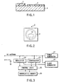
- FIG. 12 is a schematic sectional view of an issuing apparatus according to a first embodiment of the present invention.
- the apparatus has a casing 87 which is formed at its one end with an insertion/ejection port 86 through which a wireless tag 20 is inserted and ejected.
- a reader/writer (R/W) 81 for reading from and writing into the wireless information storage unit 40 in the wireless tag 20 in a non-contact manner and an image printer (PRT) 82 for erasing old information and recording new information on the effective recording area 44 of the image recording unit 30 of the wireless tag.
- the reader/writer 81 and the image printer 82 are disposed serially with respect to the insertion/ejection port 86. That is, the reader/writer is located between the port and the printer.
- Two pairs of carrying rollers 84 are provided within the casing, which constitute a carrying means 83 for carrying the wireless tag 20 inserted into the port 86 to the reader/writer 81 and the printer 82 and ejecting the tag through the port from the casing.
- the carrying means is further provided with a platen roller 85 which is opposed to the thermal head in the printer 82.
- a first sensor 88 which detects the insertion or ejection of the wireless tag 20 into or from the apparatus.
- a second sensor 89 which detects the feed of the wireless tag 20 into the printer 82.
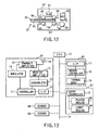
- FIG. 13 is a block diagram of the issuing apparatus of FIG. 12.
- the reader/writer 81 comprises an I/F 10, a controller 11 including a CPU, a RAM, and a ROM, a demodulator 12, a receive amplifier 13, a modulator 14, a transmit amplifier 15, and an antenna 16.
- the printer 82 comprises an I/F 17, a controller 18, and a line type of thermal head 19.
- the head is substantially equal in width to the effective recording area 44 and is positioned in a place where the effective recording area passes.
- the carrying means 83 comprises a controller 90, two sets of rollers 84, and the platen roller 85.
- the two sets of rollers 84 carry the wireless tag while sandwiching only its both ends in the direction of width. That is, the LSI chip 43 is kept away from the rollers.
- the platen roller 85 is substantially equal in width to the thermal head 19 and is opposed to the head.
- the issuing apparatus includes a CPU 71 for controlling the entire apparatus.
- the CPU is connected by a bus 72 to the reader/writer 81, the printer 82, the carrying means 83, and the first and second sensors 88 and 89.
- FIG. 14 is a flowchart illustrating an outline of the issuing procedure.
- visual information is printed on the image recording unit 30 of a wireless tag 20 in step S10, information sent by radio is written into the wireless information storage unit in the tag 40 in step S20, and the written information is checked to issue the wireless tag in step S30.
- the wireless tag 20 is first inserted through the insertion/ejection port 86 into the casing 87 of the issuing apparatus with its effective recording area 44 placed at the head (step S1).
- the CPU 71 detects the wireless tag (step S2)
- the CPU 71 outputs a carrying signal to the carrying controller 90.
- the controller then activates a carrying driver not shown to rotate the carrying rollers 84 and the eject roller 85, thereby carrying the wireless tag to the printer 82 at a given speed (step S3).
- step S10 visual information is printed.
- FIG. 15 is a detailed flowchart for the printing operation of the printer.
- the thermal head 19 moves downward from a place where it does not come into contact with the tag to a place where it comes into contact with the tag. In corporation with the platen roller 85, the thermal head 19 comes into contact with the effective recording area with pressure (step S12).
- the CPU 71 transfers visual information to the recording controller 18 via the I/F 17 (step S13).
- the information includes, as shown in FIG. 7A, destination information "HOKKAIDO", recipient information "000 COMPANY", bar-code information concerning an article to which the wireless tag is to be attached, recordeding position information, etc.
- the recording controller 18 drives each heated element of the thermal head in accordance with predetermined conditions.
- information already printed on the effective recording area as shown in FIG. 7B, the destination 80 "KAWASAKI”, the recipient 81 "000 COMPANY", and the bar code 82 is rewritten through the use of an overwriting technique to be described later by the destination 90 "HOKKAIDO", the recipient 91 "000 COMPANY", and the bar code 92 (step S14) as shown in FIG. 7A.
- the coloring (recording) and discoloring (erasing) characteristics of the rewritable recording layer 37 of the image recording unit 30 of the wireless tag 20 remain unchanged from those shown in FIG. 5.
- FIG. 18 shows the manner in which the line type thermal head 19 rewrites information already recorded.
- an existing image 92, an alphabetic character "A”, recorded on the image recording unit 30 of the wireless tag 20 is rewritten by a new image 97, an alphabetic character "B", by heating the recording unit by a string of heated elements 99 of the thermal head 19 while moving the tag in the direction of an arrow.
- each of dots of the existing image is indicated by a white dot
- each dot of the new image is indicated by a black dot.
- the thermal head 19 is controlled for each heated element 99.
- the applied energy to each heated element is selectively switched to a recording energy and an erasing energy in accordance with image information to be printed.
- the heated elements supplied with the recording energy are each indicated by a black square, whereas the heated elements supplied with the erasing energy are each indicated by a square with oblique lines.
- the thermal head 19 Upon termination of the recording of the image information (step S15), the thermal head 19 returns to the original position, thereby releasing the pressure contact with the wireless tag (step S16). Thus, the printing of image information on the image recording unit 30 terminates.
- the effective recording area 44 and the LSI chip 43 are separated from each other in the direction of length of the tag. Since, as described previously, the wireless tag is fed into the printer 82 with the effective recording area side at the head, the LSI chip will never come into contact with the thermal head 19. That is, the LSI chip will never be subjected to mechanical and thermal stress by the thermal head.
- FIG. 16 is a detailed flowchart for the operation of writing information sent by radio into the memory of the wireless tag 20.
- the carrying controller 90 reverses the rotation of the rollers 84 and 85 to carry the tag back in the direction of the insertion/ejection port 86 in step S21.
- the tag When the second sensor 89 detects the trailing edge of the tag 20 on the recording area side (step S22), the tag is carried to the position where it is opposed to the antenna 16 of the reader/writer 81 after a lapse of a predetermined time from the time at which the second sensor produced a detected signal. Then, the CPU 71 sends information to the reader/writer 81 (step S23).
- destination information "HOKKAIDO”, recipient information "000 COMPANY”, and information concerning an article to which the tag is to be attached are sent from the CPU 71 to the controller 11 comprised of CPU, RAM, and ROM.
- the information from the controller 11 is subjected in the modulator 14 to modulation suitable for transmission by radio (step S24) and the modulated information is transmitted from the antenna 16 through the transmit amplifier 15 (step S25).
- the transmitted information is received by the antenna 42 of the wireless tag 20 (step S26).
- the received signal is rectified and stabilized in the power generator 21 to apply a supply voltage to the LSI chip 43.
- the received signal is also demodulated in the demodulator 23 (step S27).
- the demodulated information is written into the nonvolatile memory 26 through the control logic 25 in such a way as to overwrite old information therein (step S28). In this manner, information is written into the wireless information storage unit 40.
- FIG. 17 is a detailed flowchart for this checking operation.
- the CPU 71 sends a read instruction to the reader/writer 81 (step S31).
- the reader/writer modulates the read instruction in the modulator 14 for transmission to the wireless tag 20 (step S32).
- the wireless tag Upon receipt of the read instruction (step S33), the wireless tag decodes it and then reads the stored information from the nonvolatile memory 26 (step S34), the information including the destination information "HOKKAIDO", the recipient information "000 COMPANY", and the article information.
- the read information is modulated in the modulator 24 and then transmitted from the antenna 42 (step S35).
- the transmitted information from the wireless tag is received by the antenna 16 (step S36) and then demodulated in the demodulator 12 after being amplified by the receive amplifier 13 (step S37).
- the demodulated information is sent through the controller 11 and the I/F 10 to the CPU 71, where the demodulated information is checked with the previously written information (step S38).
- step S41 of FIG. 14 the electronic tag 20 is ejected from the insertion/ejection port 86 in step S41 of FIG. 14. If no coincidence occurs, then the procedure returns to step S23 of FIG. 16 to repeat the information writing steps beginning with step S23 and the subsequent checking steps.
- the wireless tag issuing apparatus of this embodiment has the insertion/ejection port 86, the reader/writer 81 and the printer 82 placed in the order mentioned, prints image information on the effective recording area 44 of the wireless tag fed from the insertion/ejection port with the effective recording area at the head by the printer 82, and writes predetermined information into the wireless information storage unit 40 in a non-contact manner by the reader/writer 81. Therefore, stored information in the wireless information storage unit 40 and image information on the image recording unit 30 can be overwritten without imposing mechanical stress on the LSI chip 43 as an electronic component. That is, the LSI chip can be prevented from being damaged at the time of issuing or reissuing wireless tags. In addition, even when the thermal head 19 prints image information, heat will not be directly transferred to the wireless information storage unit, preventing written information from being destroyed by heat. Thus, the reliability and safety of the wireless tag issuing can be increased.
- thermal head-based overwrite recording permits one single printer to print and erase visual information, reducing the size of the entire apparatus.
- FIG. 19 is a flowchart illustrating an outline of the issuing operation of this embodiment.
- This method is characterized in that information written into the wireless information storage unit 40 is checked immediately after printing of image information on the image recording unit 30 of the wireless tag 20. The procedure is performed in the order of writing of information into the wireless information storage unit 40 (step S60), printing of visual information on the image recording unit 30 (step S70), and checking of the written information (step S80) as shown in FIG. 19.
- This issuing method is implemented using the same issuing apparatus as that shown in FIGS. 12 and 13.
- the wireless tag 20 is first inserted through the insertion/ejection port 86 into the casing 87 of the issuing apparatus with its effective recording area 44 placed at the head (step S51).
- the CPU 71 detects the wireless tag (step S52)
- the CPU 71 outputs a carrying signal to the carrying controller 90.
- the controller then activates a carrying driver not shown to rotate the carrying rollers 84 and the eject roller 85, thereby carrying the wireless tag to the printer 82 at a given speed (step S53).
- step S60 When the wireless tag is carried to a place where it is opposed to the antenna 16 of the reader/writer 81 after a lapse of a predetermined time from the time at which the first sensor 88 produced a detected signal, information sent by radio is written into the wireless information storage unit 40 to overwrite old information (step S60).
- FIG. 20 is a detailed flowchart for the operation of writing information by radio.
- Predetermined wireless information which, in this example, includes destination information "HOKKAIDO", recipient information "000 COMPANY", and article information, is sent from the CPU 71 through the I/F 10 to the controller 11 (step S61).
- Data from the controller 11 is modulated in the modulator 14 (step S62).
- the modulated information is sent by radio from the antenna 16 to the wireless tag 20 (step S63).
- the modulated information signal is received by the antenna 42 of the wireless tag 20 (step S63).
- the power generator 21 supplies a supply voltage to the LSI chip 43.
- the received signal is demodulated in the demodulator 23 (step S65) and then overwrites old information in the memory 26 (step S66). Thus, the writing of information into the wireless information storage unit 40 terminates.
- FIG. 21 is a flowchart for the visual information printing operation.
- the thermal head 19 moves downward from a place where it does not come into contact with the tag to a place where it comes into contact with the tag. In corporation with the platen roller 85, the thermal head 19 comes into contact with the effective recording area with pressure (step S72).
- the CPU 71 transfers visual information to the recording controller 18 via the I/F 17 (step S73).
- the information includes destination information "HOKKAIDO", recipient information "000 COMPANY”, bar-code information indicating part of information concerning an article to which the wireless tag is to be attached, and recorded position information.
- the recording controller 18 drives the thermal head in accordance with predetermined conditions.
- information already printed on the effective recording area as shown in FIG. 7B, the destination information 93 "KAWASAKI”, the recipient information 94 "000 COMPANY", and the bar code 95 is rewritten through the use of an overwriting technique to be described later by destination information 90 "HOKKAIDO", recipient information 91 "000 COMPANY", and bar code 92 (step S74) as shown in FIG. 7A.
- the thermal head 19 Upon termination of the recording of the image information, the thermal head 19 returns to the original position, thereby releasing the pressure contact with the wireless tag (step S76).
- the carrying controller 90 reverses the rotation of the rollers 84 and 85 to carry the tag in the direction of the insertion/ejection port 86 (step S77). Thus, the printing of image information on the image recording unit 30 terminates.
- the wireless tag 20 is carried to the position in which it is opposed to the antenna 16 of the reader/writer 81 after a lapse of a predetermined time from the time at which the second sensor 89 detected the trailing edge of the tag.
- the information stored in the wireless information storage unit 40 of the tag is read and then checked with the information previously used in writing.
- FIG. 22 is a detailed flowchart for the checking operation.
- the CPU 71 sends a read instruction to the reader/writer 81 (step S81).
- the reader/writer sends the read instruction to the wireless tag 20 by radio (step S82).
- the wireless tag Upon receipt of the read instruction (step S83), the wireless tag reads the previously stored information from the nonvolatile memory 26 (step S84), the information including the destination information "HOKKAIDO", the recipient information "000 COMPANY", and the article information.
- the read information is modulated in the modulator 45 and then transmitted from the antenna 42 (step S85).
- the transmitted information from the wireless tag is received by the antenna 16 (step S86) and then recovered in the demodulator 12 after being amplified by the receive amplifier 13 (step S87).
- the recovered information is sent through the controller 11 and the I/F 10 to the CPU 71, where the recovered information is checked with the previously written information (step S88).
- step S91 the electronic tag 20 is ejected from the insertion/ejection port 86 (step S91). If no coincidence occurs, then the procedure returns to step S23 of FIG. 16 to repeat the information writing steps beginning with step S23 and the subsequent checking steps.
- a wireless tag issuing method and apparatus can be provided which permit wireless information storage media to be issued without damaging an built-in electronic component.
- the wireless information storage medium may take any other form, for example, a price tag.
Landscapes
- Engineering & Computer Science (AREA)
- Physics & Mathematics (AREA)
- General Physics & Mathematics (AREA)
- Theoretical Computer Science (AREA)
- Computer Hardware Design (AREA)
- Microelectronics & Electronic Packaging (AREA)
- Computer Networks & Wireless Communication (AREA)
- General Engineering & Computer Science (AREA)
- Credit Cards Or The Like (AREA)
- Heat Sensitive Colour Forming Recording (AREA)
- Accessory Devices And Overall Control Thereof (AREA)
- Record Information Processing For Printing (AREA)
Description
For example, the base member may consist of plastic, such as polyethylene terephthalate or vinyl chloride resin, paper, such as wood free paper, or synthetic paper. In this example, a sheet of synthetic paper of about 60 µm in thickness is used. The wireless
Claims (7)
- An apparatus for issuing a wireless information storage medium (20) provided with a wireless information storage unit (2, 32, 40, 51, 62, 76) having a memory section (26) for storing information and a wireless transmitter/receiver section for transmitting and receiving information by radio and an image recording area (30) which is placed away from the memory section and on which visual information is to be printed, comprising:an insertion/ejection port (86) for inserting or ejecting the wireless information storage medium;printing means (82) for printing visual information corresponding to at least part of information to be written into the memory section on the image recording area;first carry means (84, step S3, S53) for carrying a wireless information storage medium inserted into the insertion/ejection port with its image recording area (30) at the head to a position where it is opposed to the printing means (82);reader/writer means (81, step S20, S60) installed between the insertion/ejection port and the printing means for writing information into the memory section in a non-contact manner; andsecond carry means (84, step S41, S91) for carrying the wireless information storage medium to the insertion/ejection port for ejection.
- The apparatus according to claim 1, characterized in that the reader/writer means (81) includes means (130, step S30, S80) for reading the information written into the memory section (26) from it and checking the read information with the information written into it.
- The apparatus according to claim 1 or 2, characterized in that the printing means includes overwrite thermal recording means (19) for simultaneously performing thermal recording and thermal erasing on the visual information recording area.
- The apparatus according to claim 2 or 3, characterized by further comprising means for writing information into the memory section again when the result of a check indicates non-coincidence and recalling the wireless information storage medium for which the check results indicate non-coincidence ever after information has been written into its memory section a predetermined number of times.
- A use of an apparatus according to one of claims 1 to 4 for performing a method of issuing a wireless information storage medium (20) provided with a wireless information storage unit (2, 32, 40, 51, 62, 76) having a memory section (26) for storing information and a wireless transmitter/receiver section (23, 24) for transmitting and receiving information by radio and an image recording unit (3, 333, 30, 56, 63, 77) on which visual information is to be printed comprising the steps of:writing the information into the memory section (26) by transmitting predetermined information to be stored into the memory section (26) to the wireless transmitter/receiver section by radio (step S20, S60); andprinting visual information corresponding at least part of information to be stored into the memory section (26) on the image recording unit of the wireless information storage medium (20) (step S10, S70).
- The use according to claim 5, further comprising the step of reading the information written into the memory section of the wireless information storage unit through the wireless transmitter/receiver section to check the stored information read from the memory section with the information before transmission to the wireless information storage unit (step S30, S80).
- The use according to claim 5 or 6, further comprising the step of performing the writing step again on the memory section of wireless information storage media for which the results of checks indicate non-coincidence (step S38, S88).
Applications Claiming Priority (9)
| Application Number | Priority Date | Filing Date | Title |
|---|---|---|---|
| JP25580897 | 1997-09-19 | ||
| JP255809/97 | 1997-09-19 | ||
| JP255805/97 | 1997-09-19 | ||
| JP25580997 | 1997-09-19 | ||
| JP25580597 | 1997-09-19 | ||
| JP25580997A JPH1196319A (en) | 1997-09-19 | 1997-09-19 | Issue processing method for wireless information storage medium |
| JP255808/97 | 1997-09-19 | ||
| JP25580897A JP3917262B2 (en) | 1997-09-19 | 1997-09-19 | Issuing processing method and issuing processing apparatus for wireless information storage medium |
| JP25580597A JPH1191273A (en) | 1997-09-19 | 1997-09-19 | Wireless information storage medium |
Publications (3)
| Publication Number | Publication Date |
|---|---|
| EP0903686A2 EP0903686A2 (en) | 1999-03-24 |
| EP0903686A3 EP0903686A3 (en) | 2001-09-26 |
| EP0903686B1 true EP0903686B1 (en) | 2003-04-02 |
Family
ID=27334463
Family Applications (1)
| Application Number | Title | Priority Date | Filing Date |
|---|---|---|---|
| EP98116207A Expired - Lifetime EP0903686B1 (en) | 1997-09-19 | 1998-08-27 | Apparatus for issuing wireless information storage media |
Country Status (3)
| Country | Link |
|---|---|
| US (1) | US6404335B1 (en) |
| EP (1) | EP0903686B1 (en) |
| DE (1) | DE69812814T2 (en) |
Families Citing this family (27)
| Publication number | Priority date | Publication date | Assignee | Title |
|---|---|---|---|---|
| US6724895B1 (en) | 1998-06-18 | 2004-04-20 | Supersensor (Proprietary) Limited | Electronic identification system and method with source authenticity verification |
| DE19846295B4 (en) * | 1998-10-07 | 2008-04-24 | Kabushiki Kaisha Sato | Printer with a device for driving transponder chips |
| DE19848779A1 (en) * | 1998-10-22 | 2000-05-04 | Moba Mobile Automation Gmbh | Device for printing on a medium |
| US6100804A (en) * | 1998-10-29 | 2000-08-08 | Intecmec Ip Corp. | Radio frequency identification system |
| US6520544B1 (en) * | 2000-01-10 | 2003-02-18 | Moore North America, Inc. | Radio frequency labels on reusable containers |
| US6977112B2 (en) * | 2000-07-10 | 2005-12-20 | Canon Finetech, Inc. | Non-contact information recording medium for ink-jet recording and image forming process |
| CN1208742C (en) * | 2000-12-04 | 2005-06-29 | 王子油化合成纸株式会社 | Logo and labels using the logo |
| US7137000B2 (en) | 2001-08-24 | 2006-11-14 | Zih Corp. | Method and apparatus for article authentication |
| US20030061947A1 (en) * | 2001-10-01 | 2003-04-03 | Hohberger Clive P. | Method and apparatus for associating on demand certain selected media and value-adding elements |
| US6815679B2 (en) * | 2002-02-13 | 2004-11-09 | Mitsubishi Paper Mills Limited | Reversible thermal recording material and method of recording image on reversible thermal recording material |
| US7564861B1 (en) * | 2002-08-22 | 2009-07-21 | 3Com Corporation | Systems and methods for compressing data |
| WO2006000655A1 (en) * | 2004-05-28 | 2006-01-05 | Ier | Method and device for forming a chip-containing label and the thus formed label |
| WO2006077645A1 (en) * | 2005-01-24 | 2006-07-27 | Fujitsu Limited | Antenna and rfid tag mounted with same |
| JP2006331976A (en) * | 2005-05-30 | 2006-12-07 | Matsushita Electric Ind Co Ltd | Manufacturing and management methods for secondary batteries |
| CN101194528B (en) * | 2005-05-31 | 2013-03-27 | 西门子企业通讯有限责任两合公司 | Localization system and localization method and mobile position data transmitter |
| JP4286813B2 (en) * | 2005-07-08 | 2009-07-01 | 富士通株式会社 | Antenna and RFID tag equipped with the same |
| US20080186184A1 (en) * | 2005-09-28 | 2008-08-07 | Visible Assets Inc. | Networked security tags for portable devices |
| ATE465467T1 (en) | 2005-12-20 | 2010-05-15 | Brother Ind Ltd | LABEL PRODUCING DEVICE |
| JP4235236B2 (en) * | 2006-09-12 | 2009-03-11 | 東芝テック株式会社 | Wireless communication device |
| EP1942444B1 (en) * | 2006-11-28 | 2014-03-19 | Brother Kogyo Kabushiki Kaisha | RFID tag information communicating apparatus |
| US8207819B2 (en) * | 2008-03-12 | 2012-06-26 | Sunrise R&D Holdings, Llc | System and method of using rewritable paper for displaying product information on product displays |
| US20130206842A1 (en) * | 2012-01-12 | 2013-08-15 | R.F Keeper, Ltd. | Re-printable rfid hard tags |
| JP6221370B2 (en) * | 2012-08-30 | 2017-11-01 | セイコーエプソン株式会社 | Medium processing apparatus and method for controlling medium processing apparatus |
| JP2018041472A (en) | 2012-08-30 | 2018-03-15 | セイコーエプソン株式会社 | Medium processing apparatus and medium processing method |
| US9370953B1 (en) * | 2015-06-15 | 2016-06-21 | Toshiba Tec Kabushiki Kaisha | Printer apparatus |
| JP7698504B2 (en) * | 2021-08-02 | 2025-06-25 | 東芝テック株式会社 | Image forming device |
| JP2025002457A (en) | 2023-06-22 | 2025-01-09 | 東芝テック株式会社 | Image forming device |
Family Cites Families (7)
| Publication number | Priority date | Publication date | Assignee | Title |
|---|---|---|---|---|
| JP2973582B2 (en) * | 1991-05-29 | 1999-11-08 | 株式会社デンソー | Electronic tagging device |
| JPH04368894A (en) * | 1991-06-15 | 1992-12-21 | Omron Corp | Non-contact recording medium |
| JPH06124369A (en) * | 1992-10-14 | 1994-05-06 | Omron Corp | Contactless card and contactless card issuing device |
| GB9222460D0 (en) * | 1992-10-26 | 1992-12-09 | Hughes Microelectronics Europa | Radio frequency baggage tag |
| US5682142A (en) * | 1994-07-29 | 1997-10-28 | Id Systems Inc. | Electronic control system/network |
| US5666159A (en) | 1995-04-24 | 1997-09-09 | Eastman Kodak Company | Electronic camera system with programmable transmission capability |
| JPH09104189A (en) * | 1995-10-09 | 1997-04-22 | Denso Corp | Information recording medium, method and device for its production |
-
1998
- 1998-08-27 EP EP98116207A patent/EP0903686B1/en not_active Expired - Lifetime
- 1998-08-27 DE DE69812814T patent/DE69812814T2/en not_active Expired - Lifetime
- 1998-09-17 US US09/154,630 patent/US6404335B1/en not_active Expired - Fee Related
Also Published As
| Publication number | Publication date |
|---|---|
| DE69812814D1 (en) | 2003-05-08 |
| DE69812814T2 (en) | 2003-12-18 |
| EP0903686A3 (en) | 2001-09-26 |
| EP0903686A2 (en) | 1999-03-24 |
| US6404335B1 (en) | 2002-06-11 |
Similar Documents
| Publication | Publication Date | Title |
|---|---|---|
| EP0903686B1 (en) | Apparatus for issuing wireless information storage media | |
| JP4008546B2 (en) | Wireless information storage medium | |
| US6002383A (en) | Polymer dispersed liquid crystal (PDLC) film using heat or an electric field to change state and the other to change back | |
| EP1857289A1 (en) | Image processing apparatus and image processing method, digital information storage medium, and reversible display recording medium | |
| JPH11134460A (en) | Non-contact IC label | |
| US5567066A (en) | Nonimpact printer with read and write systems for monitoring ribbon usage | |
| JP4011894B2 (en) | Card having information recording unit and reversible display unit, and issuing method using the same | |
| JP2001334693A (en) | Electronic shelf label write / erase device and writable / erasable electronic shelf label | |
| JP3476830B2 (en) | Apparatus for reading and image addition of printable card-shaped data storage medium | |
| JP2007080162A (en) | Ic tag, ic tag reader/writer and ic tag using system | |
| CN102975508B (en) | Reversible thermosensitive recording medium | |
| JPH10287072A (en) | IC card and manufacturing method thereof | |
| JP3917262B2 (en) | Issuing processing method and issuing processing apparatus for wireless information storage medium | |
| JP3716087B2 (en) | IC card issuing system and IC card issuing method | |
| US20050200884A1 (en) | Image forming apparatus | |
| JP2002331798A (en) | Information recording medium, transfer sheet used for producing the same, and method for producing information recording medium using this transfer sheet | |
| JP2002103654A (en) | Reversible thermosensitive recording device and reversible thermosensitive recording card | |
| JPH1191273A (en) | Wireless information storage medium | |
| JP2000309169A (en) | Thermal recording card, label, image processing method, image display method, and image processing apparatus | |
| JP2003030619A (en) | IC chip package | |
| JPH1196319A (en) | Issue processing method for wireless information storage medium | |
| JP2009073068A (en) | Card reader device | |
| JP2000006563A (en) | Article management article and article management system | |
| JP2002288622A (en) | IC built-in tag | |
| JP2003030617A (en) | IC chip package |
Legal Events
| Date | Code | Title | Description |
|---|---|---|---|
| PUAI | Public reference made under article 153(3) epc to a published international application that has entered the european phase |
Free format text: ORIGINAL CODE: 0009012 |
|
| 17P | Request for examination filed |
Effective date: 19980827 |
|
| AK | Designated contracting states |
Kind code of ref document: A2 Designated state(s): AT BE CH CY DE DK ES FI FR GB GR IE IT LI LU MC NL PT SE Kind code of ref document: A2 Designated state(s): DE FR GB |
|
| AX | Request for extension of the european patent |
Free format text: AL;LT;LV;MK;RO;SI |
|
| PUAL | Search report despatched |
Free format text: ORIGINAL CODE: 0009013 |
|
| AK | Designated contracting states |
Kind code of ref document: A3 Designated state(s): AT BE CH CY DE DK ES FI FR GB GR IE IT LI LU MC NL PT SE |
|
| AX | Request for extension of the european patent |
Free format text: AL;LT;LV;MK;RO;SI |
|
| 17Q | First examination report despatched |
Effective date: 20020221 |
|
| AKX | Designation fees paid |
Free format text: DE FR GB |
|
| GRAH | Despatch of communication of intention to grant a patent |
Free format text: ORIGINAL CODE: EPIDOS IGRA |
|
| GRAH | Despatch of communication of intention to grant a patent |
Free format text: ORIGINAL CODE: EPIDOS IGRA |
|
| GRAA | (expected) grant |
Free format text: ORIGINAL CODE: 0009210 |
|
| AK | Designated contracting states |
Designated state(s): DE FR GB |
|
| REG | Reference to a national code |
Ref country code: GB Ref legal event code: FG4D |
|
| REF | Corresponds to: |
Ref document number: 69812814 Country of ref document: DE Date of ref document: 20030508 Kind code of ref document: P |
|
| ET | Fr: translation filed | ||
| PLBE | No opposition filed within time limit |
Free format text: ORIGINAL CODE: 0009261 |
|
| STAA | Information on the status of an ep patent application or granted ep patent |
Free format text: STATUS: NO OPPOSITION FILED WITHIN TIME LIMIT |
|
| 26N | No opposition filed |
Effective date: 20040105 |
|
| PGFP | Annual fee paid to national office [announced via postgrant information from national office to epo] |
Ref country code: DE Payment date: 20130821 Year of fee payment: 16 |
|
| PGFP | Annual fee paid to national office [announced via postgrant information from national office to epo] |
Ref country code: FR Payment date: 20130808 Year of fee payment: 16 Ref country code: GB Payment date: 20130821 Year of fee payment: 16 |
|
| REG | Reference to a national code |
Ref country code: DE Ref legal event code: R119 Ref document number: 69812814 Country of ref document: DE |
|
| GBPC | Gb: european patent ceased through non-payment of renewal fee |
Effective date: 20140827 |
|
| REG | Reference to a national code |
Ref country code: DE Ref legal event code: R119 Ref document number: 69812814 Country of ref document: DE Effective date: 20150303 |
|
| REG | Reference to a national code |
Ref country code: FR Ref legal event code: ST Effective date: 20150430 |
|
| PG25 | Lapsed in a contracting state [announced via postgrant information from national office to epo] |
Ref country code: DE Free format text: LAPSE BECAUSE OF NON-PAYMENT OF DUE FEES Effective date: 20150303 Ref country code: GB Free format text: LAPSE BECAUSE OF NON-PAYMENT OF DUE FEES Effective date: 20140827 |
|
| PG25 | Lapsed in a contracting state [announced via postgrant information from national office to epo] |
Ref country code: FR Free format text: LAPSE BECAUSE OF NON-PAYMENT OF DUE FEES Effective date: 20140901 |