EP0903608A2 - Dispositif pour le guidage d'un faisceau - Google Patents
Dispositif pour le guidage d'un faisceau Download PDFInfo
- Publication number
- EP0903608A2 EP0903608A2 EP98307534A EP98307534A EP0903608A2 EP 0903608 A2 EP0903608 A2 EP 0903608A2 EP 98307534 A EP98307534 A EP 98307534A EP 98307534 A EP98307534 A EP 98307534A EP 0903608 A2 EP0903608 A2 EP 0903608A2
- Authority
- EP
- European Patent Office
- Prior art keywords
- lenses
- light signal
- beam steerer
- lens
- optical
- Prior art date
- Legal status (The legal status is an assumption and is not a legal conclusion. Google has not performed a legal analysis and makes no representation as to the accuracy of the status listed.)
- Withdrawn
Links
Images


Classifications
-
- G—PHYSICS
- G02—OPTICS
- G02B—OPTICAL ELEMENTS, SYSTEMS OR APPARATUS
- G02B26/00—Optical devices or arrangements for the control of light using movable or deformable optical elements
- G02B26/08—Optical devices or arrangements for the control of light using movable or deformable optical elements for controlling the direction of light
- G02B26/0808—Optical devices or arrangements for the control of light using movable or deformable optical elements for controlling the direction of light by means of one or more diffracting elements
-
- G—PHYSICS
- G02—OPTICS
- G02B—OPTICAL ELEMENTS, SYSTEMS OR APPARATUS
- G02B26/00—Optical devices or arrangements for the control of light using movable or deformable optical elements
- G02B26/08—Optical devices or arrangements for the control of light using movable or deformable optical elements for controlling the direction of light
- G02B26/0875—Optical devices or arrangements for the control of light using movable or deformable optical elements for controlling the direction of light by means of one or more refracting elements
Definitions
- This invention relates to beam steerers arranged to direct light signals in free space optical communications systems.
- light and optical as used in this patent specification are not intended to be confined to visible light, as light of any wavelength may be employed in free space optical communications.
- Free space optical communications typically involves the transfer of information, from one point to another, as a modulation impressed on a light beam, such as a laser beam.
- Beam steerers are employed in free space optical communications systems to steer very narrow light signals, which are of the order of microradians to a few tens of microradians wide, with sufficient accuracy to ensure that a receiver is continuously illuminated.
- the angular range over which a light signal is steered may be very large, the solid angle sometimes extending to greater than a hemisphere.
- beam steering typically is carried out in two stages.
- the first stage employs a coarse steering mechanism, which points the beam approximately in the desired direction.
- the second stage employs a fine steering mechanism, which removes the residual pointing error so that the beam illuminates accurately the desired point.
- conventional beam steerers employ tiltable mirrors, arranged to reflect the light signal towards the desired direction.
- a problem which may be encountered with such beam steerers is that, in order to steer the light signal through a small angle, the mirrors have to be moved precisely at high speed by very small amounts.
- a beam steerer suitable for laser radar applications is described in "Agile Beam Steering Using Binary Optics Microlens Arrays" (Goltsos et al, Optical Engineering, November 1990, Vol. 9, No. 11, Page 1392).
- This article discloses a microlens array being employed to sweep a wide laser beam through large angles.
- the microlens array causes the incident beam to be split up, which is undesirable in the field of optical communications as the laser beam carries information.
- the invention provides a beam steerer arranged to direct a light signal in a free space optical communications system, the beam steerer having a pair of lenses through which a light signal is transmissible, the lenses having opposite and substantially equal optical power, and displacing means for translating one lens with respect to the other, transverse to an optical axis of the lenses, in order to steer the light signal.
- the provision of lenses permits selection of the angular deflection of the beam per unit distance translation of a lens, as this ratio is directly proportional to the optical power of the lenses. This selection is not possible in beam steerers employing mirrors.
- the lenses can be chosen so that this ratio is small enough to give more accurate beam steering than was possible hitherto with beam steerers employing mirrors.
- the invention permits a light signal having an undivided wave front to be transmitted.
- the displacing means is arranged to translate the lenses along orthogonal axes. This feature permits the beam to be steered in any direction within a cone, the limits of which correspond to the maximum angular deflection.
- the displacing means preferably incorporates one or more electromagnetic actuators, for instance voice coils.
- the lenses have a focal length of at least ten centimetres and a maximum aperture of one centimetre.
- satellites 1 and 2 are shown in orbit around the earth.
- Information such as data, pictures or speech is transmissible between satellites 1 and 2 by means of an infrared beam of laser light.
- Each satellite has an optical device comprising an optical transmitter and an optical receiver, so that light signals can be transmitted from satellite 1 to satellite 2 and vice versa, i.e. the satellites are bidirectionally linked.
- the transmitting satellite 1 incorporates a beam steerer 5 indicated generally by broken lines.
- the beam steerer has a coarse steering mechanism (not shown), which steers the beam in approximately the desired direction.
- Coarse steering typically involves the gimballing of a large optical element e.g. a large mirror, a telescope or even an entire optical system. It is desirable to be able to fine steer the beam to a greater precision than is achievable by coarse steering alone, in order to illuminate accurately the receiver 4 on satellite 2.
- slight disturbances which can occur within a satellite can cause a light signal to miss its target.
- the firing of ion thrusters and the acoustic output of mechanisms, such as reaction wheels can cause such disturbances.
- the bandwidth of these disturbances is very broad and extends from very low frequencies up to several hundred Hz.
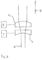
- the beam steerer includes a fine steering mechanism as shown schematically in Figure 2.
- the fine steering portion of the beam steerer comprises lenses 6 and 7 and displacing means in the form of voice coils, which are represented by boxes 8 and 9 for clarity.
- the lenses 6 and 7 have substantially the same optical power, but are of opposite sign i.e. lens 6 is positive and lens 7 is negative.
- Lens 6 is fixed in a lens mount 10. Flexures 11 and 12, which are shown as thin, flexible blades, extend transversely from two opposite sides of the mount 10, the other ends of the flexures being attached to two opposite sides of a support frame 13. Lens 7 is also fixed into a mount 14. Flexures 15 and 16 extend from the other opposite sides of the frame 13 and are fixed to opposite sides of the mount 14. The lenses 6 and 7 are arranged to be as close as possible whilst still allowing independent movement of each lens. Preferably, the lenses 6 and 7 are optically coaxial.
- the beam steerer is relatively insensitive to misalignment of the lenses, such as displacement of one lens along the optical axis, tilting of the optical axis of one lens with respect to that of the other or misalignment of the beam steerer with respect to the light beam to be steered. This is advantageous over prior art beam steerers employing mirrors which have to be accurately aligned in the optical system of the transmitter or receiver.
- the lens displacing means i.e. one of or both voice coils 8 and 9, is actuated.
- a voice coil is an example of an electromagnetic actuator, that is to say, a device that converts electromagnetic energy into mechanical work.
- Voice coils are used typically in loudspeakers.
- Voice coil 8 comprises a solenoid which translationally moves, relative to a fixed magnet, when a current is passed through it.
- Voice coil 8 is arranged so that the magnet is attached to frame 14 and the moveable coil acts on lens mount 10.
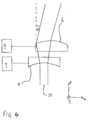
- voice coil 8 translates the positive lens 6 along the x-axis. This is shown in Figure 4.
- the translation of the positive lens 6 with respect to the negative lens 7 causes the collimated beam 17 to emerge tilted at an angle ⁇ to the optical axis, in the x-z plane.
- the tilt angle ⁇ is dependent on both the relative displacement of one lens with respect to the other and also on the optical power of the lenses.
- the other voice coil 9 when actuated, translates the negative lens 7 along the y-axis. Such a translation causes an angular deflection of the emerging beam in the y-z plane.
- the voice coils 8 and 9 are arranged so that motion in both positive and negative x- and y-axes can be effected.
- An alternative arrangement is to employ voice coils to drive one of the lenses along both the x-axis and the y-axis, to steer the beam.
- voice coils to drive one of the lenses along both the x-axis and the y-axis, to steer the beam.
- the receiving satellite 2 also has a beam steerer constructed according to the invention.
- the light beam 17 received by receiver 4 on satellite 2 is transmitted through the beam steerer and is input to a position-sensitive detector, such as a CCD.
- the position of the received signal on the detector is compared with a desired position, which is normally the centre of the detector.
- An electrical signal is fed back to the voice coils, so that any misalignment of the received beam is corrected.
- the beam steerer is arranged to be in the paths of both received and transmitted light signals so that corrections applied to the position of an incoming beam automatically ensure that an outgoing beam points in the right direction, i.e. towards the receiver on satellite 1.
- Satellite 1 also incorporates such a closed-loop feedback circuit to be applied to light signals that it receives.
- Lenses particularly suitable for inclusion in the invention are those having apertures of no more than one centimetre and focal lengths of ten centimetres or greater.
- Types of lenses that may be employed in the invention include fresnel lenses, diffractive lenses, holographic lenses and compound lenses, although this list is not exhaustive.
- a further beam steerer constructed according to the invention may be included in a satellite, in the path of a transmitted light signal, to compensate for the relative velocity of the receiving spacecraft with respect to the transmitting craft.
- the light signal is directed just ahead of a receiver on the spacecraft so that, by the time the light signal has reached the receiving craft, the receiver is at that same point.
- Further beam steerers may be incorporated in a satellite to direct a plurality of light beams such that the beams are coaligned, each beam steerer being arranged to direct one light beam.
- the invention is not limited to providing optical communication between satellites. For instance, it could be used for aircraft to ground, ground to space or ground to ground communications.
- the invention is not limited to steering a light signal of infrared laser light, as a light beam of any wavelength may be steered.
Landscapes
- Physics & Mathematics (AREA)
- General Physics & Mathematics (AREA)
- Optics & Photonics (AREA)
- Optical Communication System (AREA)
Applications Claiming Priority (2)
| Application Number | Priority Date | Filing Date | Title |
|---|---|---|---|
| GB9719975A GB2329483A (en) | 1997-09-20 | 1997-09-20 | Beam steerer with two lenses with equal and opposite powers |
| GB9719975 | 1997-09-20 |
Publications (2)
| Publication Number | Publication Date |
|---|---|
| EP0903608A2 true EP0903608A2 (fr) | 1999-03-24 |
| EP0903608A3 EP0903608A3 (fr) | 1999-12-01 |
Family
ID=10819350
Family Applications (1)
| Application Number | Title | Priority Date | Filing Date |
|---|---|---|---|
| EP98307534A Withdrawn EP0903608A3 (fr) | 1997-09-20 | 1998-09-16 | Dispositif pour le guidage d'un faisceau |
Country Status (2)
| Country | Link |
|---|---|
| EP (1) | EP0903608A3 (fr) |
| GB (1) | GB2329483A (fr) |
Cited By (15)
| Publication number | Priority date | Publication date | Assignee | Title |
|---|---|---|---|---|
| DE19804209C2 (de) * | 1998-02-03 | 2001-08-02 | Fraunhofer Ges Forschung | Vorrichtung zur Ausleuchtung einer Fläche unter einem veränderbaren Lichteinfallswinkel |
| WO2003089971A3 (fr) * | 2002-04-22 | 2004-02-26 | Cyberoptics Corp | Dispositif optique a compensation d'alignement |
| GB2415792A (en) * | 2002-04-22 | 2006-01-04 | Cyberoptics Corp | Optical device with alignment compensation |
| US7369334B2 (en) | 2001-02-20 | 2008-05-06 | Cyberoptics Corporation | Optical device with alignment compensation |
| US9423879B2 (en) | 2013-06-28 | 2016-08-23 | Chia Ming Chen | Systems and methods for controlling device operation according to hand gestures |
| US9587804B2 (en) | 2012-05-07 | 2017-03-07 | Chia Ming Chen | Light control systems and methods |
| US9717118B2 (en) | 2013-07-16 | 2017-07-25 | Chia Ming Chen | Light control systems and methods |
| US10406967B2 (en) | 2014-04-29 | 2019-09-10 | Chia Ming Chen | Light control systems and methods |
| CN112987282A (zh) * | 2021-03-10 | 2021-06-18 | 南京英田光学工程股份有限公司 | 同轨卫星激光通信用基于镜片横向移动的光束指向方法 |
| WO2021211163A1 (fr) * | 2020-04-17 | 2021-10-21 | Exciting Technology LLC | Orientation de faisceau lumineux de lentille décentrée, multifaisceau et à haute capacité |
| US11822205B2 (en) | 2020-04-17 | 2023-11-21 | Exciting Technology LLC | System, method, and apparatus for high precision light beam steering using rotating lens elements |
| US11835838B2 (en) | 2017-10-27 | 2023-12-05 | Exciting Technology LLC | System, method and apparatus for non-mechanical optical and photonic beam steering |
| CN117583624A (zh) * | 2022-08-15 | 2024-02-23 | 通用电气公司 | 能量束引导装置 |
| US12461422B2 (en) | 2017-10-27 | 2025-11-04 | Exciting Technology LLC | System, method, and apparatus to steer an electromagnetic beam utilizing staged steering |
| US12468208B2 (en) | 2018-10-23 | 2025-11-11 | Exciting Technology LLC | System, method and apparatus for non-mechanical optical and photonic beam steering |
Families Citing this family (1)
| Publication number | Priority date | Publication date | Assignee | Title |
|---|---|---|---|---|
| GB201805275D0 (en) | 2018-03-29 | 2018-05-16 | Archangel Lightworks Ltd | Wide aperture optical communications |
Family Cites Families (3)
| Publication number | Priority date | Publication date | Assignee | Title |
|---|---|---|---|---|
| US4636043A (en) * | 1984-03-01 | 1987-01-13 | Laser Photonics, Inc. | Laser beam scanning device and marking system |
| US5059008A (en) * | 1990-03-26 | 1991-10-22 | General Electric Company | Wide angle beam steerer using translation of plural lens arrays |
| US5477383A (en) * | 1993-02-05 | 1995-12-19 | Apa Optics, Inc. | Optical array method and apparatus |
-
1997
- 1997-09-20 GB GB9719975A patent/GB2329483A/en not_active Withdrawn
-
1998
- 1998-09-16 EP EP98307534A patent/EP0903608A3/fr not_active Withdrawn
Cited By (29)
| Publication number | Priority date | Publication date | Assignee | Title |
|---|---|---|---|---|
| DE19804209C2 (de) * | 1998-02-03 | 2001-08-02 | Fraunhofer Ges Forschung | Vorrichtung zur Ausleuchtung einer Fläche unter einem veränderbaren Lichteinfallswinkel |
| US7369334B2 (en) | 2001-02-20 | 2008-05-06 | Cyberoptics Corporation | Optical device with alignment compensation |
| GB2415792A (en) * | 2002-04-22 | 2006-01-04 | Cyberoptics Corp | Optical device with alignment compensation |
| GB2403817B (en) * | 2002-04-22 | 2006-02-01 | Cyberoptics Corp | Optical device with alignment compensation |
| GB2415792B (en) * | 2002-04-22 | 2006-06-07 | Cyberoptics Corp | Optical device with alignment compensation |
| GB2403817A (en) * | 2002-04-22 | 2005-01-12 | Cyberoptics Corp | Optical device with alignment compensation |
| WO2003089971A3 (fr) * | 2002-04-22 | 2004-02-26 | Cyberoptics Corp | Dispositif optique a compensation d'alignement |
| US9587804B2 (en) | 2012-05-07 | 2017-03-07 | Chia Ming Chen | Light control systems and methods |
| US9423879B2 (en) | 2013-06-28 | 2016-08-23 | Chia Ming Chen | Systems and methods for controlling device operation according to hand gestures |
| US9717118B2 (en) | 2013-07-16 | 2017-07-25 | Chia Ming Chen | Light control systems and methods |
| US10406967B2 (en) | 2014-04-29 | 2019-09-10 | Chia Ming Chen | Light control systems and methods |
| US10953785B2 (en) | 2014-04-29 | 2021-03-23 | Chia Ming Chen | Light control systems and methods |
| US11835838B2 (en) | 2017-10-27 | 2023-12-05 | Exciting Technology LLC | System, method and apparatus for non-mechanical optical and photonic beam steering |
| US12461422B2 (en) | 2017-10-27 | 2025-11-04 | Exciting Technology LLC | System, method, and apparatus to steer an electromagnetic beam utilizing staged steering |
| US12468208B2 (en) | 2018-10-23 | 2025-11-11 | Exciting Technology LLC | System, method and apparatus for non-mechanical optical and photonic beam steering |
| US20220350136A1 (en) * | 2020-04-17 | 2022-11-03 | Exciting Technology, Llc | High capability, multi-beam, decentered lens light beam steering |
| WO2021211163A1 (fr) * | 2020-04-17 | 2021-10-21 | Exciting Technology LLC | Orientation de faisceau lumineux de lentille décentrée, multifaisceau et à haute capacité |
| US20220360037A1 (en) * | 2020-04-17 | 2022-11-10 | Exciting Technology, Llc | Decentered lens light beam steering |
| US12578615B2 (en) | 2020-04-17 | 2026-03-17 | Exciting Technology LLC | System, method, and apparatus for high precision light beam steering |
| US11822205B2 (en) | 2020-04-17 | 2023-11-21 | Exciting Technology LLC | System, method, and apparatus for high precision light beam steering using rotating lens elements |
| US12405460B2 (en) * | 2020-04-17 | 2025-09-02 | Exciting Technology LLC | Decentered lens light beam steering |
| EP4127813A4 (fr) * | 2020-04-17 | 2024-04-03 | Exciting Technology LLC | Orientation de faisceau lumineux de lentille décentrée |
| US12248139B2 (en) | 2020-04-17 | 2025-03-11 | Exciting Technology LLC | Decentered lens light beam steering |
| US12379640B2 (en) | 2020-04-17 | 2025-08-05 | Exciting Technology LLC | System, method, and apparatus for high precision light beam steering using a triplet lens |
| CN112987282A (zh) * | 2021-03-10 | 2021-06-18 | 南京英田光学工程股份有限公司 | 同轨卫星激光通信用基于镜片横向移动的光束指向方法 |
| EP4332656A1 (fr) * | 2022-08-15 | 2024-03-06 | General Electric Company | Dispositif de guidage de faisceau d'énergie |
| JP2024028691A (ja) * | 2022-08-15 | 2024-03-05 | ゼネラル・エレクトリック・カンパニイ | エネルギビーム方向付け装置 |
| US12569913B2 (en) | 2022-08-15 | 2026-03-10 | General Electric Company | Energy beam directing device |
| CN117583624A (zh) * | 2022-08-15 | 2024-02-23 | 通用电气公司 | 能量束引导装置 |
Also Published As
| Publication number | Publication date |
|---|---|
| GB9719975D0 (en) | 1997-11-19 |
| GB2329483A (en) | 1999-03-24 |
| EP0903608A3 (fr) | 1999-12-01 |
Similar Documents
| Publication | Publication Date | Title |
|---|---|---|
| EP0903608A2 (fr) | Dispositif pour le guidage d'un faisceau | |
| US6268944B1 (en) | Free-space optical lasercom system | |
| US6347001B1 (en) | Free-space laser communication system having six axes of movement | |
| EP0607906B1 (fr) | Système de réglage d'alignement pour l'utilisation dans un système d'émetteur-récepteur optique | |
| US5062150A (en) | Fiber-based free-space optical system | |
| US5390040A (en) | Optical transceiver for free-space communication links | |
| US6091528A (en) | Optical communication system of space propagation type | |
| US7246949B2 (en) | Device for transmitting optical signals | |
| US4823402A (en) | Agile optical beam steering system | |
| EP0977070B1 (fr) | Téléscope avec un chemin optique commun pour un terminal optique de communication | |
| EP0814356A2 (fr) | Capteur d'image avec champs optiques multiples utilisant des optiques réfléchissantes | |
| WO1986001307A1 (fr) | Systeme stabilisateur modulaire adaptable | |
| US4576449A (en) | Sighting mirror including a stabilizing device | |
| US7292789B1 (en) | Multi-channel wide-field laser communications method and apparatus | |
| US6104478A (en) | System for uninterrupted light beam deflection | |
| US20060180739A1 (en) | Beam steering for optical target identification and tracking without gimbals or scanning mirrors | |
| US12061334B2 (en) | Optical scanning system using micro-electro-mechanical system (mems) micro-mirror arrays (MMAs) | |
| Page | Design of the Optical Communication Demonstrator instrument optical system | |
| Saathof et al. | Opto-mechatronics system development for future intersatellite laser communications | |
| RU2328077C1 (ru) | Устройство двухсторонней оптической связи | |
| Czichy et al. | Diffractive optics for advanced free space laser communication terminals | |
| Fischer et al. | Advanced optical solutions for inter-satellite communications | |
| Mai et al. | Variable focus lens-based optical beam steering and adaptive beam control techniques for free-space optical communications | |
| RU242480U1 (ru) | Коллиматор лазерного излучения для формирования канала связи между космическими аппаратами формата Cubesat | |
| Clarke et al. | Experimental results with a prototype three-channel multiaccess transceiver lasercom terminal |
Legal Events
| Date | Code | Title | Description |
|---|---|---|---|
| PUAI | Public reference made under article 153(3) epc to a published international application that has entered the european phase |
Free format text: ORIGINAL CODE: 0009012 |
|
| AK | Designated contracting states |
Kind code of ref document: A2 Designated state(s): AT BE CH CY DE DK ES FI FR GB GR IE IT LI LU MC NL PT SE |
|
| AX | Request for extension of the european patent |
Free format text: AL;LT;LV;MK;RO;SI |
|
| PUAL | Search report despatched |
Free format text: ORIGINAL CODE: 0009013 |
|
| AK | Designated contracting states |
Kind code of ref document: A3 Designated state(s): AT BE CH CY DE DK ES FI FR GB GR IE IT LI LU MC NL PT SE |
|
| AX | Request for extension of the european patent |
Free format text: AL;LT;LV;MK;RO;SI |
|
| AKX | Designation fees paid | ||
| REG | Reference to a national code |
Ref country code: DE Ref legal event code: 8566 |
|
| STAA | Information on the status of an ep patent application or granted ep patent |
Free format text: STATUS: THE APPLICATION IS DEEMED TO BE WITHDRAWN |
|
| 18D | Application deemed to be withdrawn |
Effective date: 20000603 |