EP0903595A2 - Bracket assembly for strain relief of optical fiber jumpers - Google Patents
Bracket assembly for strain relief of optical fiber jumpers Download PDFInfo
- Publication number
- EP0903595A2 EP0903595A2 EP98307005A EP98307005A EP0903595A2 EP 0903595 A2 EP0903595 A2 EP 0903595A2 EP 98307005 A EP98307005 A EP 98307005A EP 98307005 A EP98307005 A EP 98307005A EP 0903595 A2 EP0903595 A2 EP 0903595A2
- Authority
- EP
- European Patent Office
- Prior art keywords
- tie
- bracket
- jumpers
- hole
- defining
- Prior art date
- Legal status (The legal status is an assumption and is not a legal conclusion. Google has not performed a legal analysis and makes no representation as to the accuracy of the status listed.)
- Withdrawn
Links
Images
Classifications
-
- G—PHYSICS
- G02—OPTICS
- G02B—OPTICAL ELEMENTS, SYSTEMS OR APPARATUS
- G02B6/00—Light guides; Structural details of arrangements comprising light guides and other optical elements, e.g. couplings
- G02B6/44—Mechanical structures for providing tensile strength and external protection for fibres, e.g. optical transmission cables
- G02B6/4439—Auxiliary devices
- G02B6/444—Systems or boxes with surplus lengths
- G02B6/4453—Cassettes
- G02B6/4454—Cassettes with splices
-
- G—PHYSICS
- G02—OPTICS
- G02B—OPTICAL ELEMENTS, SYSTEMS OR APPARATUS
- G02B6/00—Light guides; Structural details of arrangements comprising light guides and other optical elements, e.g. couplings
- G02B6/44—Mechanical structures for providing tensile strength and external protection for fibres, e.g. optical transmission cables
- G02B6/4439—Auxiliary devices
- G02B6/444—Systems or boxes with surplus lengths
- G02B6/4452—Distribution frames
- G02B6/44524—Distribution frames with frame parts or auxiliary devices mounted on the frame and collectively not covering a whole width of the frame or rack
-
- G—PHYSICS
- G02—OPTICS
- G02B—OPTICAL ELEMENTS, SYSTEMS OR APPARATUS
- G02B6/00—Light guides; Structural details of arrangements comprising light guides and other optical elements, e.g. couplings
- G02B6/44—Mechanical structures for providing tensile strength and external protection for fibres, e.g. optical transmission cables
- G02B6/4439—Auxiliary devices
- G02B6/444—Systems or boxes with surplus lengths
- G02B6/44528—Patch-cords; Connector arrangements in the system or in the box
-
- G—PHYSICS
- G02—OPTICS
- G02B—OPTICAL ELEMENTS, SYSTEMS OR APPARATUS
- G02B6/00—Light guides; Structural details of arrangements comprising light guides and other optical elements, e.g. couplings
- G02B6/44—Mechanical structures for providing tensile strength and external protection for fibres, e.g. optical transmission cables
- G02B6/4439—Auxiliary devices
- G02B6/4471—Terminating devices ; Cable clamps
- G02B6/44765—Terminating devices ; Cable clamps with means for strain-relieving to exterior cable layers
Definitions
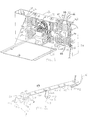
- Bracket assembly 10 comprises bracket 48 with length portion 50 with first end 52 and second end 54 opposite thereto.
- Length portion 50 also has top surface 56, first edge 58 and second edge 60.
- Top surface defines mounting holes 62 therethrough for receiving projections 64 of fanning finger blocks 66 snap-fit thereihrough.
- Fanning finger blocks 66 are known in the art and are commonly used in optical hardware to manage the routing of jumpers
- One or more blocks 66 are mounted in line along top surface 56 to define a line of routing spaces 68 between successive curved fingers 70.
- Bracket assembly 10 is located on surface 42 such that the line of routing spaces 68 can receive jumpers 36 therethrough in a managed fashion.
- jumpers 36 are routed through routing spaces 68 and curve to pass over a tie portion 80.
- a cable tie is threaded through one of the holes 84 and its respective cut-out 86 and wrapped around the jumpers and cinched closed to provide strain relief for the jumpers. With web 88 as thin as appropriate without compromising its strength the circumferential cinching area of the cable tie 96 around the jumpers is maximized. If one of the jumpers is snagged or pulled at a point outside of cabinet 12, the strain of such pull will be relieved at the cable tie 96 and tie portion 80 and will not be transferred to the connectors 34 and adapters 24. More than one cable tie 96 can be used if desired.
Landscapes
- Physics & Mathematics (AREA)
- General Physics & Mathematics (AREA)
- Optics & Photonics (AREA)
- Light Guides In General And Applications Therefor (AREA)
- Installation Of Indoor Wiring (AREA)
Abstract
Description
Claims (6)
- A bracket assembly for managing and strain relieving optical fiber jumpers, comprising:(a) a bracket with a length portion defining a top surface extending longitudinally between a first end and a second end and having a width between a first edge and a second edge, the bracket having a tie portion extending laterally from the first edge at the first end to define a free edge, the tie portion defining at least one hole adjacent the free edge defining a web between the hole and the free edge, the hole sized to allow threading of a cable tie therethrough;(b) at least one fanning finger block mounted on the top surface and having a plurality of fanning fingers defining a line of routing spaces along the top surface for receiving jumpers routed therethrough; and(c) the hole in the tie portion being located relative to the line of routing spaces such that it would be disposed generally underneath a jumper that is routed through the routing spaces in a direction generally perpendicular to the length portion from the side of the bracket opposite the tie portion and curved within minimum bend radius constraints to run parallel with the length portion and over the tie portion.
- The bracket assembly of Claim 1 wherein the free edge of the tie portion defines at least one cut-out adjacent the at least one hole such that the web is defined between the hole and the cut-out, the cut-out having a width to allow passage of a cable tie therethrough.
- The bracket assembly of Claim 1 or 2 wherein the bracket further comprises a second tie portion at the second end of the length portion.
- The bracket assembly of any one of Claims 1-3 wherein the bracket further comprises mounting portions extending downwardly from the length portion and having a foot for mounting to a surface so as to define a clearance space underneath the tie portion.
- A bracket assembly for strain relieving optical fiber jumpers, comprising:(a) a bracket having a planar tie portion having a free edge, the tie portion defining a series of holes therethrough, each hole sized to allow threading of a cable tie therethrough, the free edge defining a series of cut-outs adjacent the series of holes and defining a web between each hole and its respective cut-out; and(b) the bracket having a mounting portion extending perpendicularly from the tie portion terminating at a free end for mounting to a suitable surface so as to define a clearance space sufficient to allow threading of a cable tie through a hole to tie jumpers to the top of the tie portion when the bracket is installed on the surface.
- The bracket assembly of Claim 5 wherein the bracket further comprises a length portion extending from the tie portion and further comprising at least one fanning finger block mounted to the top surface defining a line of routing spaces for routing a plurality of jumpers from a direction perpendicular to the length portion, the series of holes spaced from the at least one fanning finger block such that the holes will be located underneath jumpers that are routed through the routing spaces and curved within bend radius constraints to run in a direction parallel to the length portion.
Applications Claiming Priority (2)
| Application Number | Priority Date | Filing Date | Title |
|---|---|---|---|
| US08/922,006 US6009223A (en) | 1997-09-02 | 1997-09-02 | Bracket assembly for strain relief of optical fiber jumpers |
| US922006 | 1997-09-02 |
Publications (2)
| Publication Number | Publication Date |
|---|---|
| EP0903595A2 true EP0903595A2 (en) | 1999-03-24 |
| EP0903595A3 EP0903595A3 (en) | 1999-12-15 |
Family
ID=25446330
Family Applications (1)
| Application Number | Title | Priority Date | Filing Date |
|---|---|---|---|
| EP98307005A Withdrawn EP0903595A3 (en) | 1997-09-02 | 1998-09-01 | Bracket assembly for strain relief of optical fiber jumpers |
Country Status (3)
| Country | Link |
|---|---|
| US (1) | US6009223A (en) |
| EP (1) | EP0903595A3 (en) |
| CA (1) | CA2245845A1 (en) |
Cited By (2)
| Publication number | Priority date | Publication date | Assignee | Title |
|---|---|---|---|---|
| WO2007027925A3 (en) * | 2005-08-31 | 2007-04-12 | Adc Telecommunications Inc | Cabinet including bulkhead plate for blown optical fiber system |
| WO2013009930A1 (en) * | 2011-07-13 | 2013-01-17 | Corning Cable Systems Llc | Fiber optic cable mounting adapters, and related fiber optic cable assemblies and methods |
Families Citing this family (16)
| Publication number | Priority date | Publication date | Assignee | Title |
|---|---|---|---|---|
| US6648280B1 (en) * | 1998-11-24 | 2003-11-18 | The Marvel Group, Inc. | Wire harness for modular office furniture |
| US6501899B1 (en) * | 2000-06-02 | 2002-12-31 | Panduit Corp. | Vertical cable management system |
| US6381393B1 (en) * | 2000-11-08 | 2002-04-30 | Adc Telecommunications, Inc. | Fanning strip for cable management panel |
| US6728461B1 (en) | 2003-03-13 | 2004-04-27 | Marc Senatore | Optical fiber cable manager |
| US7345241B2 (en) * | 2005-01-18 | 2008-03-18 | Panduit Corp. | Cable management support bar with strain relief clamps |
| US7693387B2 (en) * | 2007-04-05 | 2010-04-06 | C.E. Communication Systems, Inc. | Cable management system |
| US7496269B1 (en) * | 2007-04-12 | 2009-02-24 | Adc Gmbh | Fiber optic enclosure |
| US7734139B2 (en) * | 2008-10-07 | 2010-06-08 | Cisco Technology, Inc. | Modular cable-management system |
| US20110211801A1 (en) * | 2010-03-01 | 2011-09-01 | Mcgranahan Daniel S | Cable Routing Guide With Cable Retainer |
| CN102402255A (en) * | 2010-09-09 | 2012-04-04 | 鸿富锦精密工业(深圳)有限公司 | Electronic device |
| EP3014719A4 (en) * | 2013-06-24 | 2017-04-19 | 3M Innovative Properties Company | Strain relief device for low friction drop cable |
| US9494761B2 (en) * | 2014-07-31 | 2016-11-15 | All Systems Broadband, Inc. | Bracket for securing multiple fiber optic cables to a termination box |
| WO2019177934A1 (en) * | 2018-03-13 | 2019-09-19 | Corning Research & Development Corporation | Enclosure for local convergence point for fiber optic communications network |
| WO2021080759A1 (en) * | 2019-10-22 | 2021-04-29 | Commscope Technologies Llc | Cable management system for base station antennas |
| CN113013802A (en) * | 2019-12-20 | 2021-06-22 | 康普技术有限责任公司 | Cable manager and cable management assembly for same |
| US12507354B1 (en) * | 2025-04-10 | 2025-12-23 | Frontier Communications Holdings, Llc | Mounting mechanism for networking device |
Family Cites Families (11)
| Publication number | Priority date | Publication date | Assignee | Title |
|---|---|---|---|---|
| US35030A (en) * | 1862-04-22 | Improvement in padlocks | ||
| US4080035A (en) * | 1977-04-13 | 1978-03-21 | Amp Incorporated | Strain relief device |
| FR2590371B1 (en) * | 1985-11-18 | 1988-09-16 | Cit Alcatel | OPTICAL CABLES HEAD CHASSIS |
| EP0250900A3 (en) * | 1986-06-25 | 1989-07-19 | Siemens Aktiengesellschaft | Distributor for telecommunication arrangements with light wave guides |
| US5274729A (en) * | 1992-07-30 | 1993-12-28 | At&T Bell Laboratories | Universal optical fiber buildout system |
| US5312270A (en) | 1992-08-25 | 1994-05-17 | The Siemon Company | Wiring block having detachable leg assemblies |
| US5373421A (en) * | 1993-06-02 | 1994-12-13 | Digital Equipment Corporation | Fiber optic transceiver mounting bracket |
| US5640482A (en) * | 1995-08-31 | 1997-06-17 | The Whitaker Corporation | Fiber optic cable management rack |
| US5724467A (en) * | 1995-10-11 | 1998-03-03 | The Whitaker Corporation | Adapter to secure fiber optic connectors within a telecommuniations box |
| US5575665A (en) * | 1995-12-01 | 1996-11-19 | Superior Modular Products Incorporated | Patch panel with hinged tie bar |
| US5731546A (en) * | 1996-03-15 | 1998-03-24 | Molex Incorporated | Telecommunications cable management tray with a row of arcuate cable guide walls |
-
1997
- 1997-09-02 US US08/922,006 patent/US6009223A/en not_active Expired - Fee Related
-
1998
- 1998-08-27 CA CA002245845A patent/CA2245845A1/en not_active Abandoned
- 1998-09-01 EP EP98307005A patent/EP0903595A3/en not_active Withdrawn
Cited By (6)
| Publication number | Priority date | Publication date | Assignee | Title |
|---|---|---|---|---|
| WO2007027925A3 (en) * | 2005-08-31 | 2007-04-12 | Adc Telecommunications Inc | Cabinet including bulkhead plate for blown optical fiber system |
| US7330626B2 (en) | 2005-08-31 | 2008-02-12 | Adc Telecommunications, Inc. | Cabinet including optical bulkhead plate for blown fiber system |
| US7657148B2 (en) | 2005-08-31 | 2010-02-02 | Adc Telecommunications, Inc. | Cabinet including optical bulkhead plate for blown fiber system |
| US7869684B2 (en) | 2005-08-31 | 2011-01-11 | Adc Telecommunications, Inc. | Cabinet including optical bulkhead plate for blown fiber system |
| WO2013009930A1 (en) * | 2011-07-13 | 2013-01-17 | Corning Cable Systems Llc | Fiber optic cable mounting adapters, and related fiber optic cable assemblies and methods |
| US8625952B2 (en) | 2011-07-13 | 2014-01-07 | Corning Cable Systems Llc | Fiber optic cable mounting adapters, and related fiber optic cable assemblies and methods |
Also Published As
| Publication number | Publication date |
|---|---|
| EP0903595A3 (en) | 1999-12-15 |
| CA2245845A1 (en) | 1999-03-02 |
| US6009223A (en) | 1999-12-28 |
Similar Documents
| Publication | Publication Date | Title |
|---|---|---|
| US6009223A (en) | Bracket assembly for strain relief of optical fiber jumpers | |
| US11002932B2 (en) | Multi-positionable telecommunications tray | |
| US6360050B1 (en) | High density fiber distribution tray system | |
| US11002931B2 (en) | Telecommunications tray with a cable routing path extending through a pivot hinge | |
| US20010036351A1 (en) | Fiber optic wall mount cabinet | |
| US6788871B2 (en) | Optical fiber connection housing with an outlet connector element and a splice connection to an optical line group | |
| US6541705B1 (en) | Cable management rack | |
| US6674952B2 (en) | Fiber optic cable bend radius protection system | |
| US5969294A (en) | Fiber optic connector cabinet with rotatably mounted adapter panels | |
| US6353696B1 (en) | Panel for managing jumper storage | |
| US7298951B2 (en) | Cable management device and method | |
| US5446822A (en) | Connector clip for fiber optic housing | |
| US6586680B1 (en) | Modular bend radius control fixture | |
| US6728461B1 (en) | Optical fiber cable manager | |
| HUP0500272A2 (en) | Fiber management module with cable storage | |
| CN1122455A (en) | Fiber optic distribution device | |
| IL125445A (en) | Optical fibre distribution system | |
| CA2313895A1 (en) | Mounting apparatus for equipment enclosures having cable bend radius control and channel for retaining cable | |
| US6996904B1 (en) | Method for managing cables | |
| US8824851B2 (en) | Communications enclosure having rear mounted bracket and method of securing a cable bundle to a communications enclosure using a rear mounted bracket | |
| US6024610A (en) | Cable connection assembly | |
| KR102350854B1 (en) | Optical terminal box | |
| US6973249B2 (en) | Optical fiber trough for an optical interconnection system | |
| HK1070140B (en) | Plugboard |
Legal Events
| Date | Code | Title | Description |
|---|---|---|---|
| PUAI | Public reference made under article 153(3) epc to a published international application that has entered the european phase |
Free format text: ORIGINAL CODE: 0009012 |
|
| AK | Designated contracting states |
Kind code of ref document: A2 Designated state(s): DE FR GB IT |
|
| AX | Request for extension of the european patent |
Free format text: AL;LT;LV;MK;RO;SI |
|
| PUAL | Search report despatched |
Free format text: ORIGINAL CODE: 0009013 |
|
| AK | Designated contracting states |
Kind code of ref document: A3 Designated state(s): AT BE CH CY DE DK ES FI FR GB GR IE IT LI LU MC NL PT SE |
|
| AX | Request for extension of the european patent |
Free format text: AL;LT;LV;MK;RO;SI |
|
| 17P | Request for examination filed |
Effective date: 20000612 |
|
| AKX | Designation fees paid |
Free format text: DE FR GB IT |
|
| STAA | Information on the status of an ep patent application or granted ep patent |
Free format text: STATUS: THE APPLICATION IS DEEMED TO BE WITHDRAWN |
|
| 18D | Application deemed to be withdrawn |
Effective date: 20030401 |