EP0903522A2 - Actuator having electrostrictive braking element - Google Patents
Actuator having electrostrictive braking element Download PDFInfo
- Publication number
- EP0903522A2 EP0903522A2 EP98115071A EP98115071A EP0903522A2 EP 0903522 A2 EP0903522 A2 EP 0903522A2 EP 98115071 A EP98115071 A EP 98115071A EP 98115071 A EP98115071 A EP 98115071A EP 0903522 A2 EP0903522 A2 EP 0903522A2
- Authority
- EP
- European Patent Office
- Prior art keywords
- actuator
- braking
- output coupling
- flywheel
- driving means
- Prior art date
- Legal status (The legal status is an assumption and is not a legal conclusion. Google has not performed a legal analysis and makes no representation as to the accuracy of the status listed.)
- Granted
Links
- 230000008878 coupling Effects 0.000 claims abstract description 20
- 238000010168 coupling process Methods 0.000 claims abstract description 20
- 238000005859 coupling reaction Methods 0.000 claims abstract description 20
- 230000003213 activating effect Effects 0.000 claims description 2
- 239000000919 ceramic Substances 0.000 claims description 2
- 230000015572 biosynthetic process Effects 0.000 claims 3
- 238000005755 formation reaction Methods 0.000 claims 3
- 239000000779 smoke Substances 0.000 description 4
- 238000012546 transfer Methods 0.000 description 3
- 238000010586 diagram Methods 0.000 description 2
- 230000007246 mechanism Effects 0.000 description 2
- 238000000034 method Methods 0.000 description 2
- 238000012986 modification Methods 0.000 description 2
- 230000004048 modification Effects 0.000 description 2
- 238000006467 substitution reaction Methods 0.000 description 2
- 206010010904 Convulsion Diseases 0.000 description 1
- 238000004378 air conditioning Methods 0.000 description 1
- 238000013459 approach Methods 0.000 description 1
- 230000008859 change Effects 0.000 description 1
- 238000013461 design Methods 0.000 description 1
- 238000007599 discharging Methods 0.000 description 1
- 238000010438 heat treatment Methods 0.000 description 1
- 238000009434 installation Methods 0.000 description 1
- 230000000670 limiting effect Effects 0.000 description 1
- 239000000463 material Substances 0.000 description 1
- 230000002265 prevention Effects 0.000 description 1
- 230000002035 prolonged effect Effects 0.000 description 1
- 230000001360 synchronised effect Effects 0.000 description 1
- 230000001052 transient effect Effects 0.000 description 1
Images


Classifications
-
- F—MECHANICAL ENGINEERING; LIGHTING; HEATING; WEAPONS; BLASTING
- F16—ENGINEERING ELEMENTS AND UNITS; GENERAL MEASURES FOR PRODUCING AND MAINTAINING EFFECTIVE FUNCTIONING OF MACHINES OR INSTALLATIONS; THERMAL INSULATION IN GENERAL
- F16K—VALVES; TAPS; COCKS; ACTUATING-FLOATS; DEVICES FOR VENTING OR AERATING
- F16K31/00—Actuating devices; Operating means; Releasing devices
- F16K31/004—Actuating devices; Operating means; Releasing devices actuated by piezoelectric means
-
- F—MECHANICAL ENGINEERING; LIGHTING; HEATING; WEAPONS; BLASTING
- F16—ENGINEERING ELEMENTS AND UNITS; GENERAL MEASURES FOR PRODUCING AND MAINTAINING EFFECTIVE FUNCTIONING OF MACHINES OR INSTALLATIONS; THERMAL INSULATION IN GENERAL
- F16K—VALVES; TAPS; COCKS; ACTUATING-FLOATS; DEVICES FOR VENTING OR AERATING
- F16K31/00—Actuating devices; Operating means; Releasing devices
- F16K31/02—Actuating devices; Operating means; Releasing devices electric; magnetic
- F16K31/04—Actuating devices; Operating means; Releasing devices electric; magnetic using a motor
- F16K31/047—Actuating devices; Operating means; Releasing devices electric; magnetic using a motor characterised by mechanical means between the motor and the valve, e.g. lost motion means reducing backlash, clutches, brakes or return means
Definitions
- the present invention relates generally to an electro-mechanical actuator which has a retracting function that resets the actuator to a predetermined default position in the event of a power failure, and more particularly relates to an actuator having an electrostrictive braking element which prevents the actuator from being retracted to the default position during a normal operation when power is applied to the braking element, and allows the actuator to be reset when the power is interrupted.
- a conventional actuator having the retracting function is used primarily in heating, ventilating and air-conditioning (HVAC) installations for actuating a damper or valve which is used to control air flow during emergency situations such as fire.
- HVAC heating, ventilating and air-conditioning
- the actuator positions the damper to a predetermined default position if the power to the actuator is terminated, whether intentionally shut off by an operator or through a power failure. In this manner, the actuator automatically displaces the damper without electric power to a safeguard position to assist in routing or containing the fire and smoke to areas that are designated by a preestablished fire prevention plan.
- the retracting function of many conventional actuators is typically performed by a mechanism such as a spring which is included in the actuator.
- a mechanism such as a spring which is included in the actuator.
- power is continually applied to the same motor in the actuator for initially displacing the damper away from the default position.
- the motor consumes power while the damper is being displaced away from the default position, and continues to draw power in a stalled condition when the damper reaches a mechanical end stop that defines the normal operating position.
- This arrangement is disadvantageous in that the motor consumes relatively large amount of power, which becomes more significant when multitude of actuators of the same type are used in some large scale HVAC systems. The total power consumption of these actuators over their lifetime can be very high and costly.
- Another object is to provide such an improved actuator which can be restored to its desired predetermined position in the event of a power failure.
- Yet another object of the present invention is to provide such an improved actuator having a braking device which is not prone to seizures and is highly reliable.
- the present invention is directed to actuators of the type having a nonelectrical retracting function which resets the actuator to a default position when the power to the actuator is disrupted. While the present invention is suited for many differing uses where dampers and valves are operated by electro-mechanical actuators, the present invention is particularly adapted for opening and closing dampers in the air ducts of a HVAC system in the event of a fire and/or smoke build-up to control the flow through the building in a desired manner that conforms with safety procedures.
- the damper and the actuator used in this application are arranged so that when the power to the actuator is disrupted, the actuator automatically displaces the damper to a predetermined default position without the use of electric power.
- the present invention is directed to an improved actuator having an electro-mechanical actuator for maintaining an external device to which the actuator is connected at an operating position when power is applied to the actuator, and allowing the external device to return to a default position when the power is interrupted.
- the actuator includes a housing and an output coupling rotatably mounted thereon.
- the output coupling is configured to be connected to the external device and displaces the external device between the operating position and the default position.
- a driving device is mounted in the housing for providing a torque to the output coupling to displace the external device between the default position and the operating position when the driving device is energized.
- a torque transmitting device for transmitting and changing the torque from the driving device to the output coupling is also provided.
- the torque transmitting device is cooperatively engaged to and is located between the driving device and the output coupling.
- a retracting device is configured for exerting a retracting force to return the external device to the default position via the transmitting device when the power is removed from the actuator.
- An important feature of the invention is a piezoelectric braking device which exerts a braking force on the driving device. The braking force exceeds the retracting force exerted by the retracting device when the braking device is activated, but is extinguished when the braking device is deactivated.
- a novel feature of the present invention is that the power required to prevent the damper from being placed in the default position during normal operation when there is no fire or smoke build-up is channeled from a motor or a solenoid to the piezoelectric braking device.
- the piezoelectric braking device operates on a significantly lower power, and thereby effectively reduces the amount of power necessary to maintain the external device at the normal operating position.
- the piezoelectric braking device is also more reliable than the conventional solenoids because there are no moving parts which can to stick to each other.
- the actuator 10 includes a housing 12 which is configured to receive a rotatable output coupler 14 through a coupling hole 16.
- the coupler 14 operatively couples with a damper (not shown), and it is adapted to displace the damper between a default position and a desired operating position as the coupler is rotated.
- Attached to the coupler 14 is an output segment 18 which rotates the coupler through its range of rotation, the boundaries of which are defined by a pair of stops 19,20. While not shown, the outer arcuate surface of the segment 18 has teeth which engage teeth of a gear wheel 22.
- a gear train indicated generally at 24, includes the gear wheel 22 that is engaged with the output segment 18 and a gear wheel 30 which is operatively engaged with a drive pinion 26 of a drive motor 28 (best seen in FIGS. 2 and 3). Additional gears wheels 32A, 32B and 32C are operatively engaged and are located between the gears 22 and 30 and complete the gear train 24. Each of the gear wheels in the gear train 24 has a transfer pinion 34 attached thereto (not all pinions shown).
- the gear train 24 is arranged with the axes of the gear wheels 22, 32A, 32B, 32C and 30 generally forming a zig-zag line from the motor 28 to the coupler 14 (best seen in FIG. 3). In this manner, when the motor 28 is energized and rotates the gear wheel 30, the torque produced by the motor is transferred via the gears wheels 32C, 32B, 32A and 22 to the output segment 18. It should be noted that while the preferred gear train 24 is arranged using interconnection of five gear wheels and their respective transfer pinions 34, a person of ordinary skill in the art will recognize that gear train 24 may include more or less than five gear wheels, and be arranged in various other configurations which would allow a transfer or change of torque from the motor 28 to the output segment 18.
- An elongated shaft 36 which is concentric with the axis of the gear wheel 32A protrudes therefrom, and is connected to an end (connection not shown) of a retracting spring 38.
- the other end of the retracting spring 38 is connected to the housing 12 (connection not shown).
- the retracting spring 38 is a clock spring, but it is contemplated that other springs may be used.
- the retracting spring 38 is held in its position by a retainer plate 40 which is configured to allow the shaft 36 to be connected to the spring 38.
- a torque pivot plate 42 which is configured to pivot around the axis of the drive motor 28.
- the pivot plate 42 includes three axles 44 fixed on the top 46 of the pivot plate 42 and arranged correspondingly with the axes of three of the gear wheels 30, 32B and 32C to allow the gear wheels to be rotated thereon (best seen in FIG. 2).
- a spring 48 has one end hooked to the pivot plate 42 and at the other end to a post 50 fixedly mounted on the retainer plate 40.
- a microswitch 54 On the bottom 52 of the pivot plate 42 is a microswitch 54 which switches as it comes into and loses contact with a stationary vertical contact arm 56 protruding from the retainer plate 40.
- the output segment 18 comes in contact with one of the stops 19,20 defining the boundary of the output segment.
- the motor 28 continues to rotate in a planetary gear like motion, thereby causing the pivot plate 42 to pivot around the drive pinion 26 of the motor against the force of the spring 48 and away from the contact arm 56.
- the microswitch 54 loses contact with the contact arm 56, which causes the microswitch 54 to switch, and thereby deenergizing the drive motor 26 and simultaneously activating a brake device 58.
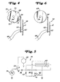
- the brake device 58 includes a piezoelectric beam 60, which in the preferred embodiment is of a multi-layer piezo ceramic beam structure.
- One end of the beam 60 is fixedly mounted to a cantilever mount 62 on a side of the housing 12, while the other end has a brake pad 64 attached thereto.
- a pair of electrical leads 66 are also connected to the beam 60 at the mount 62.
- the brake pad 64 is adjacent a flywheel 68 which includes notches 70 formed on the edge thereof.
- the notches 70 are configured and dimensioned so that the brake pad 64 is allowed to matingly lock onto the notches without slipping out when the flywheel 68 is rotated in the direction indicated by an arrow 72, and so that the brake pad is prevented from being caught in the notches in the event the drive motor 28 were to re-engage following a transient power interruption and rotate in the opposing direction of the arrow 72.
- the drive motor 28 is coupled to the flywheel 68 (best seen in FIG. 1) and drives the flywheel.
- the motor 28 itself is mounted in the housing 12, and in the preferred embodiment is a shaded-pole ac motor, although other suitable motors are contemplated, such as dc brushed motors, ac synchronous motors or brushless dc motors.
- the actuator 10 remains in this suspended state until the voltage applied to the beam 60 is interrupted as a result of a fire or smoke build-up signal being generated. This causes the beam 60 to release its lock on the flywheel 68 and return to its form prior to the application of voltage, away from the flywheel, at which time the retracting spring 38 forces the output coupler 14 to bring the damper into the default position.
- FIG.5 a schematic diagram is shown of one embodiment of a circuit, indicated generally at 74, for controlling the piezoelectric beam 60.
- a rectifier diode 76 is connected downstream of the switch 54 for converting the ac voltage from an input source 78 to the dc voltage which is supplied to the piezoelectric beam 60.
- a pair of discharge diodes 79, 80 are also included and are connected to the beam 60 for discharging the beam 60 when the dc voltage output from the diode 76 is removed therefrom.
- the switch 54 is a double-pole, double-throw switch and connects the ac input source 78 to the motor 28 and the discharge diodes 79, 80 to ground via a resistor 82, as depicted in FIG. 5 in position A, to place the damper in the normal operating position.
- the switch 54 When the switch 54 is in this position, the supply of input dc voltage to the piezo beam 60 is interrupted and the charge on the beam, if any, is discharged through the diodes 79, 80 to ground.
- the switch 54 connects the input voltage source 78 to the rectifier diode 76 and disconnects the discharge diodes 79, 80 from ground, as depicted in FIG. 5 in position B.
- the beam 60 When the circuit 74 is placed in this configuration, the beam 60 activates and bends towards the flywheel 68 to lock onto the notches 70 (best seen in FIG. 4). The beam 60 cannot discharge through the diodes 78, 80 because they are effectively eliminated from the circuit 74 when the switch 54 is in position B.
- FIG. 6 another embodiment of the present invention is shown in which the flywheel 68 does not have the notches 70 (the same numbers used in FIG. 4 will also be used to describe the features shown in FIG. 5).
- the piezoelectric brake device 58 of FIG. 5 bends towards and away from the flywheel 68 depending on the application of voltage on the beam 60.
- the brake device 58 of this embodiment applies a substantial frictional load on the flywheel 68 as the brake pad 64 makes contact with the flywheel.
- additional methods may be used to stop the:rotation of the flywheel 68, for example, bumps or other protrusions affixed to the perimeter of the flywheel.
Landscapes
- Engineering & Computer Science (AREA)
- General Engineering & Computer Science (AREA)
- Mechanical Engineering (AREA)
- Braking Arrangements (AREA)
- Air-Flow Control Members (AREA)
- Connection Of Motors, Electrical Generators, Mechanical Devices, And The Like (AREA)
- Respiratory Apparatuses And Protective Means (AREA)
- Electrically Driven Valve-Operating Means (AREA)
- General Electrical Machinery Utilizing Piezoelectricity, Electrostriction Or Magnetostriction (AREA)
Abstract
Description
Claims (15)
- An electro-mechanical actuator for maintaining an external device to which said actuator is connected, at an operating position when power is applied to the actuator and allowing said device to return to a default position when the power is removed, said actuator comprising:a housing;an output coupling rotatably mounted on said housing and configured to be connected to the device, said output coupling being adapted to displace the external device between the operating position and the default position;driving means, mounted in said housing, for providing a torque to said output coupling to displace said external device between the default position and the operating position when said driving means is energized;torque transmitting means for transmitting and changing said torque from said driving means to said output coupling, said torque transmitting means being cooperatively engaged to and located between said driving means and said output coupling;retracting means operatively connected to said torque transmitting means and configured for exerting a retracting force to return the device to the default position via said transmitting means when the power to said actuator is removed; anda piezoelectric braking means for exerting a braking force on said driving means for maintaining said output coupling at said operating position against the retracting force exerted by the retracting means when said braking means is activated, and for releasing said braking force when said braking means is deactivated.
- The actuator as defined in claim 1 wherein said driving means is an electric motor having a flywheel rotatably attached thereto.
- The actuator as defined in claim 2 wherein said braking force is applied to said flywheel.
- The actuator as defined in claim 3 wherein said flywheel has formations on an edge thereof, said braking means being configured for latching onto said formations.
- The actuator as defined in claim 4 wherein said formations are notches formed into said flywheel.
- The actuator as defined in claim 1 wherein said torque transmitting means is a gear train for increasing said torque being applied to said output coupling from said driving means.
- The actuator as defined in claim 1 further including switching means for deenergizing said driving means and activating said braking means when said switching means is energized.
- The actuator as defined in claim 7 wherein said switching means is a microswitch.
- The actuator as defined in claim 7 further including a torque plate pivotally attached to said driving means and configured for energizing said switching means when said output coupling reaches said operating position.
- The actuator as defined in claim 1 wherein said retracting means is a clock spring.
- The actuator as defined in claim 1 wherein said braking means includes a stationary post and a beam structure having a first end fixedly attached said post and a second end arranged and configured for exerting said braking force on said driving means when said braking means is activate.
- The actuator as defined in claim 11 wherein said beam structure includes at least one piezoelectric ceramic strip.
- The actuator as defined in claim 11 wherein said braking means is activated by a control circuit, said control circuit applying a voltage to said beam structure for deflecting said second end towards said driving means.
- The actuator as defined in claim 13 wherein said driving means includes a flywheel rotatably attached thereto and said second end has a pad attached thereto, said pad making a frictional contact with said flywheel when said braking means is activated.
- The actuator as defined in claim 13 wherein said driving means includes a flywheel rotatably attached thereto, said flywheel having notches formed thereon, and wherein said second end matingly locks onto said notches when said braking means is activated.
Applications Claiming Priority (2)
| Application Number | Priority Date | Filing Date | Title |
|---|---|---|---|
| US08/914,519 US5986369A (en) | 1997-08-19 | 1997-08-19 | Actuator having piezoelectric braking element |
| US914519 | 1997-08-19 |
Publications (3)
| Publication Number | Publication Date |
|---|---|
| EP0903522A2 true EP0903522A2 (en) | 1999-03-24 |
| EP0903522A3 EP0903522A3 (en) | 2001-01-31 |
| EP0903522B1 EP0903522B1 (en) | 2005-05-04 |
Family
ID=25434471
Family Applications (1)
| Application Number | Title | Priority Date | Filing Date |
|---|---|---|---|
| EP98115071A Expired - Lifetime EP0903522B1 (en) | 1997-08-19 | 1998-08-11 | Actuator having electrostrictive braking element |
Country Status (11)
| Country | Link |
|---|---|
| US (1) | US5986369A (en) |
| EP (1) | EP0903522B1 (en) |
| JP (1) | JP4171110B2 (en) |
| KR (1) | KR100544391B1 (en) |
| CN (1) | CN1102857C (en) |
| AU (1) | AU732836B2 (en) |
| CA (1) | CA2237248C (en) |
| DE (1) | DE69830031T2 (en) |
| IL (1) | IL125565A0 (en) |
| NZ (1) | NZ331168A (en) |
| TW (1) | TW434981B (en) |
Cited By (7)
| Publication number | Priority date | Publication date | Assignee | Title |
|---|---|---|---|---|
| EP1347249A1 (en) * | 2002-03-20 | 2003-09-24 | Invensys Building Systems | Manual override and locking mechanism and actuator including same |
| EP1368230A4 (en) * | 2001-03-15 | 2005-04-13 | Stoneridge Control Devices Inc | Actuator and integrated position control |
| KR100544391B1 (en) * | 1997-08-19 | 2006-05-09 | 시멘스 빌딩 테크놀로지스, 인코포레이티드 | Actuator with electric distortion brake |
| US7066301B2 (en) | 2002-03-20 | 2006-06-27 | Invensys Building Systems, Inc. | Linear actuator having manual override and locking mechanism |
| EP1754916A1 (en) * | 2005-08-16 | 2007-02-21 | Wilo Ag | Valve with piezoelectric element |
| WO2008007058A3 (en) * | 2006-07-10 | 2009-01-15 | Rotork Controls | Improvements to valve actuators |
| EP2562451A1 (en) * | 2011-08-23 | 2013-02-27 | Valeo Systèmes de Contrôle Moteur | Three-way valve |
Families Citing this family (24)
| Publication number | Priority date | Publication date | Assignee | Title |
|---|---|---|---|---|
| US6178369B1 (en) * | 1998-01-30 | 2001-01-23 | Continental Teves Ag & Co., Ohg | Method and regulating system for applying defined actuating forces |
| US6651952B1 (en) * | 1998-11-12 | 2003-11-25 | Barber Colman Company | Two position rotary actuator incorporating DC solenoid |
| US6097123A (en) * | 1999-06-03 | 2000-08-01 | Johnson Controls Technology Company | Brake and stall detector for a motorized actuator |
| DE10133630A1 (en) * | 2001-07-11 | 2003-01-30 | Siemens Ag | Electric motor drive |
| US6679356B2 (en) * | 2002-01-23 | 2004-01-20 | Delphi Technologies, Inc. | Brake caliper backdrive apparatus and method |
| US7021415B2 (en) * | 2002-02-01 | 2006-04-04 | Stoneridge Control Devices, Inc. | Electro-mechanical actuator for an electrically actuated parking brake |
| DE60325772D1 (en) * | 2002-11-13 | 2009-02-26 | Stoneridge Control Devices Inc | ELECTROMECHANICAL ACTUATOR FOR AN ELECTRICALLY ACTUATED PARKING BRAKE |
| US7021072B2 (en) | 2003-04-24 | 2006-04-04 | Honeywell International Inc. | Current control loop for actuator and method |
| US6979965B2 (en) * | 2003-04-24 | 2005-12-27 | Honeywell International Inc. | Spring return actuator for a damper |
| GB2425160B (en) * | 2005-04-12 | 2010-11-17 | Perpetuum Ltd | An Electromechanical Generator for, and method of, Converting Mechanical Vibrational Energy into Electrical Energy |
| US20060272444A1 (en) * | 2005-06-03 | 2006-12-07 | Ray Cockerham | Electromechanical cable actuator assembly controller |
| KR100734394B1 (en) * | 2006-09-07 | 2007-07-02 | 주식회사 은하양행 | Spring return valve actuator |
| US20100056039A1 (en) * | 2007-04-12 | 2010-03-04 | Belimo Holding Ag | Drive system for a fire protection flap |
| US8587170B2 (en) | 2008-05-21 | 2013-11-19 | Siemens Industry, Inc. | Actuator arrangement with worm gear and rotational output having an encoder |
| BRPI0822952B1 (en) * | 2008-07-18 | 2021-03-09 | Flowserve Management Company | valve actuator, system for actuating a valve, method of operation of a valve actuator and method of actuation of an electrically actuated valve actuator |
| US10094485B2 (en) | 2008-07-18 | 2018-10-09 | Flowserve Management Company | Variable-speed actuator |
| JP5376115B2 (en) * | 2008-08-27 | 2013-12-25 | ミツミ電機株式会社 | Driving method of driving device |
| US8084982B2 (en) | 2008-11-18 | 2011-12-27 | Honeywell International Inc. | HVAC actuator with output torque compensation |
| US8084980B2 (en) | 2009-01-30 | 2011-12-27 | Honeywell International Inc. | HVAC actuator with internal heating |
| GB2514374A (en) * | 2013-05-21 | 2014-11-26 | Johnson Electric Sa | Electrically operated valve assembly |
| JP6571395B2 (en) * | 2015-05-29 | 2019-09-04 | 日本電産サンキョー株式会社 | Damper device |
| WO2021228780A1 (en) | 2020-05-11 | 2021-11-18 | Rotiny Aps | Actuator for fluid flow controllers |
| CN112161096B (en) * | 2020-10-27 | 2025-01-07 | 泰州市都瑞堡船舶设备有限公司 | An electric damper capable of closing quickly |
| DE102021209914B3 (en) | 2021-09-08 | 2022-10-13 | Siemens Schweiz Ag | Actuator with an electrically switched on and off, non-contact magnetic detent detent for holding or releasing a rotor bucket of an actuator motor |
Family Cites Families (29)
| Publication number | Priority date | Publication date | Assignee | Title |
|---|---|---|---|---|
| US3192416A (en) * | 1963-07-16 | 1965-06-29 | Hoover Co | Synchronous motor with limit control |
| US3302043A (en) * | 1963-07-16 | 1967-01-31 | Hoover Co | Synchronous electric motor |
| US3297889A (en) * | 1964-01-15 | 1967-01-10 | Breskend Sam | Clock driver |
| US3808895A (en) * | 1973-02-09 | 1974-05-07 | J Fitzwater | Electric fail-safe actuator |
| JPS5245299U (en) * | 1975-09-27 | 1977-03-30 | ||
| JPS575644U (en) * | 1980-06-11 | 1982-01-12 | ||
| US4623044A (en) * | 1983-12-22 | 1986-11-18 | Jidosha Kiki Co., Ltd. | Brake apparatus |
| US4602702A (en) * | 1983-12-28 | 1986-07-29 | Jidosha Kiki Co., Ltd. | Brake apparatus |
| US4689516A (en) * | 1985-05-02 | 1987-08-25 | Kabushiki Kaisha Toshiba | Position adjustment device with a piezoelectric element as a lock mechanism |
| US4581987A (en) * | 1985-05-30 | 1986-04-15 | Ecm Motor Co. | Fire damper actuator |
| JPS6283521A (en) * | 1985-10-09 | 1987-04-17 | Nippon Electric Ind Co Ltd | Piezoelectric friction brake |
| US4621789A (en) * | 1985-11-04 | 1986-11-11 | Rikuo Fukamachi | Electrically driven valve |
| US4669578A (en) * | 1986-03-13 | 1987-06-02 | Rikuo Fukamachi | Motor driven valve |
| DE3608550A1 (en) * | 1986-03-14 | 1987-09-17 | Festo Kg | Piezoelectrically actuated valve |
| JPS6338779A (en) * | 1986-07-31 | 1988-02-19 | Keihin Seiki Mfg Co Ltd | Motor operated valve |
| US4741508A (en) * | 1987-04-13 | 1988-05-03 | Rikuo Fukamachi | Actuator for valve |
| CA1319331C (en) * | 1987-04-17 | 1993-06-22 | Kouhei Yamatoh | Brake device |
| JPH0511385Y2 (en) * | 1988-05-30 | 1993-03-22 | ||
| US4890027A (en) * | 1988-11-21 | 1989-12-26 | Hughes Aircraft Company | Dynamic motor controller |
| JPH02126670U (en) * | 1989-03-28 | 1990-10-18 | ||
| US5090518A (en) * | 1990-05-31 | 1992-02-25 | General Motors Corporation | Brake control system |
| JPH05277200A (en) * | 1992-04-16 | 1993-10-26 | Kuken Denki Kk | Opening/closing device for fire prevention damper |
| JPH0738844U (en) * | 1993-12-20 | 1995-07-14 | 株式会社松井製作所 | A valve that operates when the power is turned off |
| JP3058813B2 (en) * | 1994-07-04 | 2000-07-04 | セイコーエプソン株式会社 | Power generation device and control method thereof |
| JPH0861404A (en) * | 1994-08-18 | 1996-03-08 | Ogura Clutch Co Ltd | Negative-acting electromagnetic brake |
| US5498143A (en) * | 1994-12-15 | 1996-03-12 | Tecumseh Products Company | Scroll compressor with flywheel |
| JPH08208378A (en) * | 1995-02-02 | 1996-08-13 | Komatsu Ltd | Feed drive device for single crystal puller |
| JP3033881U (en) * | 1996-07-22 | 1997-02-07 | 大東テック株式会社 | Motor damper |
| US5986369A (en) * | 1997-08-19 | 1999-11-16 | Siemens Building Technologies, Inc. | Actuator having piezoelectric braking element |
-
1997
- 1997-08-19 US US08/914,519 patent/US5986369A/en not_active Expired - Lifetime
-
1998
- 1998-05-08 CA CA002237248A patent/CA2237248C/en not_active Expired - Lifetime
- 1998-07-28 AU AU78544/98A patent/AU732836B2/en not_active Expired
- 1998-07-28 NZ NZ331168A patent/NZ331168A/en unknown
- 1998-07-29 IL IL12556598A patent/IL125565A0/en unknown
- 1998-08-11 DE DE69830031T patent/DE69830031T2/en not_active Expired - Lifetime
- 1998-08-11 EP EP98115071A patent/EP0903522B1/en not_active Expired - Lifetime
- 1998-08-11 TW TW087112274A patent/TW434981B/en not_active IP Right Cessation
- 1998-08-18 JP JP23163798A patent/JP4171110B2/en not_active Expired - Lifetime
- 1998-08-18 KR KR1019980033460A patent/KR100544391B1/en not_active Expired - Lifetime
- 1998-08-19 CN CN98118455A patent/CN1102857C/en not_active Expired - Lifetime
Cited By (13)
| Publication number | Priority date | Publication date | Assignee | Title |
|---|---|---|---|---|
| KR100544391B1 (en) * | 1997-08-19 | 2006-05-09 | 시멘스 빌딩 테크놀로지스, 인코포레이티드 | Actuator with electric distortion brake |
| EP1368230A4 (en) * | 2001-03-15 | 2005-04-13 | Stoneridge Control Devices Inc | Actuator and integrated position control |
| EP1347249A1 (en) * | 2002-03-20 | 2003-09-24 | Invensys Building Systems | Manual override and locking mechanism and actuator including same |
| US6725976B2 (en) | 2002-03-20 | 2004-04-27 | Invensys Building Systems Inc. | Manual override and locking mechanism and actuator including same |
| US7066301B2 (en) | 2002-03-20 | 2006-06-27 | Invensys Building Systems, Inc. | Linear actuator having manual override and locking mechanism |
| EP1754916A1 (en) * | 2005-08-16 | 2007-02-21 | Wilo Ag | Valve with piezoelectric element |
| WO2008007058A3 (en) * | 2006-07-10 | 2009-01-15 | Rotork Controls | Improvements to valve actuators |
| US8118276B2 (en) | 2006-07-10 | 2012-02-21 | Rotork Controls Limited | Valve actuators |
| EP2562451A1 (en) * | 2011-08-23 | 2013-02-27 | Valeo Systèmes de Contrôle Moteur | Three-way valve |
| FR2979410A1 (en) * | 2011-08-23 | 2013-03-01 | Valeo Sys Controle Moteur Sas | VALVE, IN PARTICULAR FOR AN AUTOMOTIVE MOTOR INTAKE CIRCUIT, COMPRISING A DRIVING MEANS FOR RETURNING A SHUTTER OFFSET IN THE EVENT OF FAILURE OF THE RECALL MEANS |
| CN103032211A (en) * | 2011-08-23 | 2013-04-10 | 法雷奥电机控制系统公司 | Three-way valve with return end-stop on the air pathway |
| US9273786B2 (en) | 2011-08-23 | 2016-03-01 | Valeo Systemes De Controle Moteur | Three-way valve with return end-stop on the air pathway |
| EP3009721A1 (en) * | 2011-08-23 | 2016-04-20 | Valeo Systèmes De Contrôle Moteur | Three-way valve with return abutment on the air channel |
Also Published As
| Publication number | Publication date |
|---|---|
| CA2237248C (en) | 2001-02-27 |
| AU732836B2 (en) | 2001-05-03 |
| DE69830031D1 (en) | 2005-06-09 |
| DE69830031T2 (en) | 2006-01-19 |
| EP0903522B1 (en) | 2005-05-04 |
| CN1221637A (en) | 1999-07-07 |
| JP4171110B2 (en) | 2008-10-22 |
| CN1102857C (en) | 2003-03-12 |
| IL125565A0 (en) | 1999-03-12 |
| KR100544391B1 (en) | 2006-05-09 |
| AU7854498A (en) | 1999-03-04 |
| NZ331168A (en) | 1998-09-24 |
| JPH11137705A (en) | 1999-05-25 |
| US5986369A (en) | 1999-11-16 |
| EP0903522A3 (en) | 2001-01-31 |
| CA2237248A1 (en) | 1999-02-19 |
| TW434981B (en) | 2001-05-16 |
| HK1023732A1 (en) | 2000-09-22 |
| KR19990023679A (en) | 1999-03-25 |
Similar Documents
| Publication | Publication Date | Title |
|---|---|---|
| US5986369A (en) | Actuator having piezoelectric braking element | |
| US6177771B1 (en) | Automatic door operator | |
| EP0944788B1 (en) | Linear actuator | |
| US6100655A (en) | Mechanical return fail-safe actuator for damper, valve, elevator or other positioning device | |
| CA2103800A1 (en) | Actuator and zone valve | |
| US5182498A (en) | Spring return rotary actuator | |
| CA2155466C (en) | An actuating drive having a spring return feature | |
| US5758684A (en) | Return-to-normal modular actuator | |
| AU645184B2 (en) | Electrical actuator with means for preventing dither at a limit switch | |
| US5970997A (en) | Smart actuator control | |
| EP1048905B1 (en) | Actuator having timer-controlled power switching device | |
| US5205534A (en) | Actuator and zone valve | |
| US6971967B2 (en) | Clutch-driven limited force actuator | |
| US5988319A (en) | Transmission for a return-to-normal actuator | |
| US5712548A (en) | Bi-directional motor actuator | |
| HK1023732B (en) | Actuator having electrostrictive braking element | |
| EP0522690A2 (en) | Drive system | |
| JPH09137873A (en) | Motor-driven actuator for regulating valve | |
| JPH03235808A (en) | Floodgate opening/closing device | |
| JPH0334530Y2 (en) | ||
| JPH06307570A (en) | Actuator for valve | |
| JP2024007062A (en) | actuator system | |
| WO2001055548A1 (en) | Drive system | |
| JPS6338779A (en) | Motor operated valve | |
| JPH01131379A (en) | Opening closing control device |
Legal Events
| Date | Code | Title | Description |
|---|---|---|---|
| PUAI | Public reference made under article 153(3) epc to a published international application that has entered the european phase |
Free format text: ORIGINAL CODE: 0009012 |
|
| AK | Designated contracting states |
Kind code of ref document: A2 Designated state(s): CH DE FR GB LI |
|
| AX | Request for extension of the european patent |
Free format text: AL;LT;LV;MK;RO;SI |
|
| RAP1 | Party data changed (applicant data changed or rights of an application transferred) |
Owner name: SIEMENS BUILDING TECHNOLOGIES, INC. |
|
| PUAL | Search report despatched |
Free format text: ORIGINAL CODE: 0009013 |
|
| AK | Designated contracting states |
Kind code of ref document: A3 Designated state(s): AT BE CH CY DE DK ES FI FR GB GR IE IT LI LU MC NL PT SE |
|
| AX | Request for extension of the european patent |
Free format text: AL;LT;LV;MK;RO;SI |
|
| 17P | Request for examination filed |
Effective date: 20010628 |
|
| AKX | Designation fees paid |
Free format text: CH DE FR GB LI |
|
| 17Q | First examination report despatched |
Effective date: 20040311 |
|
| GRAP | Despatch of communication of intention to grant a patent |
Free format text: ORIGINAL CODE: EPIDOSNIGR1 |
|
| GRAS | Grant fee paid |
Free format text: ORIGINAL CODE: EPIDOSNIGR3 |
|
| GRAA | (expected) grant |
Free format text: ORIGINAL CODE: 0009210 |
|
| AK | Designated contracting states |
Kind code of ref document: B1 Designated state(s): CH DE FR GB LI |
|
| REG | Reference to a national code |
Ref country code: GB Ref legal event code: FG4D |
|
| REG | Reference to a national code |
Ref country code: CH Ref legal event code: EP |
|
| REF | Corresponds to: |
Ref document number: 69830031 Country of ref document: DE Date of ref document: 20050609 Kind code of ref document: P |
|
| PLBE | No opposition filed within time limit |
Free format text: ORIGINAL CODE: 0009261 |
|
| STAA | Information on the status of an ep patent application or granted ep patent |
Free format text: STATUS: NO OPPOSITION FILED WITHIN TIME LIMIT |
|
| ET | Fr: translation filed | ||
| 26N | No opposition filed |
Effective date: 20060207 |
|
| REG | Reference to a national code |
Ref country code: CH Ref legal event code: NV Representative=s name: SIEMENS SCHWEIZ AG |
|
| REG | Reference to a national code |
Ref country code: CH Ref legal event code: PFA Owner name: SIEMENS INDUSTRY, INC. Free format text: SIEMENS BUILDING TECHNOLOGIES, INC.#1000 DEERFIELD PARKWAY#BUFFALO GROVE, ILLINOIS 60089 (US) -TRANSFER TO- SIEMENS INDUSTRY, INC.#3333 OLD MILTON PARKWAY#ALPHARETTA, GA 30005 (US) |
|
| REG | Reference to a national code |
Ref country code: FR Ref legal event code: TP |
|
| REG | Reference to a national code |
Ref country code: FR Ref legal event code: PLFP Year of fee payment: 19 |
|
| REG | Reference to a national code |
Ref country code: FR Ref legal event code: PLFP Year of fee payment: 20 |
|
| PGFP | Annual fee paid to national office [announced via postgrant information from national office to epo] |
Ref country code: FR Payment date: 20170814 Year of fee payment: 20 Ref country code: GB Payment date: 20170811 Year of fee payment: 20 |
|
| PGFP | Annual fee paid to national office [announced via postgrant information from national office to epo] |
Ref country code: DE Payment date: 20171019 Year of fee payment: 20 |
|
| PGFP | Annual fee paid to national office [announced via postgrant information from national office to epo] |
Ref country code: CH Payment date: 20171110 Year of fee payment: 20 |
|
| REG | Reference to a national code |
Ref country code: DE Ref legal event code: R071 Ref document number: 69830031 Country of ref document: DE |
|
| REG | Reference to a national code |
Ref country code: CH Ref legal event code: PL |
|
| REG | Reference to a national code |
Ref country code: GB Ref legal event code: PE20 Expiry date: 20180810 |
|
| PG25 | Lapsed in a contracting state [announced via postgrant information from national office to epo] |
Ref country code: GB Free format text: LAPSE BECAUSE OF EXPIRATION OF PROTECTION Effective date: 20180810 |