EP0903486A2 - Dispositif et procédé diagnostique du capteur dans un système de régulation à contre-réaction de la combustion - Google Patents
Dispositif et procédé diagnostique du capteur dans un système de régulation à contre-réaction de la combustion Download PDFInfo
- Publication number
- EP0903486A2 EP0903486A2 EP19980306229 EP98306229A EP0903486A2 EP 0903486 A2 EP0903486 A2 EP 0903486A2 EP 19980306229 EP19980306229 EP 19980306229 EP 98306229 A EP98306229 A EP 98306229A EP 0903486 A2 EP0903486 A2 EP 0903486A2
- Authority
- EP
- European Patent Office
- Prior art keywords
- combustion
- conductive path
- voltage level
- set forth
- fault condition
- Prior art date
- Legal status (The legal status is an assumption and is not a legal conclusion. Google has not performed a legal analysis and makes no representation as to the accuracy of the status listed.)
- Withdrawn
Links
- 238000002485 combustion reaction Methods 0.000 title claims abstract description 96
- 238000000034 method Methods 0.000 title claims abstract description 17
- 230000003287 optical effect Effects 0.000 claims description 2
- 239000000446 fuel Substances 0.000 description 11
- 239000000523 sample Substances 0.000 description 9
- 239000000203 mixture Substances 0.000 description 8
- 239000002826 coolant Substances 0.000 description 3
- 238000001514 detection method Methods 0.000 description 3
- 238000010586 diagram Methods 0.000 description 3
- XLYOFNOQVPJJNP-UHFFFAOYSA-N water Substances O XLYOFNOQVPJJNP-UHFFFAOYSA-N 0.000 description 3
- 238000004891 communication Methods 0.000 description 2
- 239000012530 fluid Substances 0.000 description 2
- VNWKTOKETHGBQD-UHFFFAOYSA-N methane Chemical compound C VNWKTOKETHGBQD-UHFFFAOYSA-N 0.000 description 2
- 230000004044 response Effects 0.000 description 2
- 150000001298 alcohols Chemical class 0.000 description 1
- 230000006835 compression Effects 0.000 description 1
- 238000007906 compression Methods 0.000 description 1
- 238000010276 construction Methods 0.000 description 1
- 230000003247 decreasing effect Effects 0.000 description 1
- 239000002283 diesel fuel Substances 0.000 description 1
- 230000000694 effects Effects 0.000 description 1
- 230000008595 infiltration Effects 0.000 description 1
- 238000001764 infiltration Methods 0.000 description 1
- 239000011810 insulating material Substances 0.000 description 1
- 238000010248 power generation Methods 0.000 description 1
- 230000001902 propagating effect Effects 0.000 description 1
- 230000003313 weakening effect Effects 0.000 description 1
- 239000002023 wood Substances 0.000 description 1
Images
Classifications
-
- F—MECHANICAL ENGINEERING; LIGHTING; HEATING; WEAPONS; BLASTING
- F02—COMBUSTION ENGINES; HOT-GAS OR COMBUSTION-PRODUCT ENGINE PLANTS
- F02D—CONTROLLING COMBUSTION ENGINES
- F02D35/00—Controlling engines, dependent on conditions exterior or interior to engines, not otherwise provided for
- F02D35/02—Controlling engines, dependent on conditions exterior or interior to engines, not otherwise provided for on interior conditions
- F02D35/022—Controlling engines, dependent on conditions exterior or interior to engines, not otherwise provided for on interior conditions using an optical sensor, e.g. in-cylinder light probe
-
- F—MECHANICAL ENGINEERING; LIGHTING; HEATING; WEAPONS; BLASTING
- F02—COMBUSTION ENGINES; HOT-GAS OR COMBUSTION-PRODUCT ENGINE PLANTS
- F02D—CONTROLLING COMBUSTION ENGINES
- F02D41/00—Electrical control of supply of combustible mixture or its constituents
- F02D41/02—Circuit arrangements for generating control signals
- F02D41/14—Introducing closed-loop corrections
- F02D41/1438—Introducing closed-loop corrections using means for determining characteristics of the combustion gases; Sensors therefor
- F02D41/1493—Details
- F02D41/1495—Detection of abnormalities in the air/fuel ratio feedback system
-
- F—MECHANICAL ENGINEERING; LIGHTING; HEATING; WEAPONS; BLASTING
- F02—COMBUSTION ENGINES; HOT-GAS OR COMBUSTION-PRODUCT ENGINE PLANTS
- F02D—CONTROLLING COMBUSTION ENGINES
- F02D35/00—Controlling engines, dependent on conditions exterior or interior to engines, not otherwise provided for
- F02D35/02—Controlling engines, dependent on conditions exterior or interior to engines, not otherwise provided for on interior conditions
- F02D35/021—Controlling engines, dependent on conditions exterior or interior to engines, not otherwise provided for on interior conditions using an ionic current sensor
Definitions
- This invention relates generally to a diagnostic apparatus and method for a combustion sensor feedback system of an internal combustion engine and more particularly to an apparatus and method for detecting fault conditions on a conductive path connecting the combustion sensor with another component of the engine such as an electronic controller.
- an electronic controller is used to control the air fuel mixture delivered to a combustion chamber of a cylinder of the engine, and produce an ignition signal in response to sensed engine parameters to ignite the mixture in engines that are spark ignited.
- the ignition signal is delivered to a spark plug which is disposed centrally in the combustion chamber, and a flame is produced when the spark ignites the air fuel mixture.
- a combustion sensor which can be an ion probe, optical device, thermocouple, or like device, is typically also located in the combustion chamber.
- Examples of conventional combustion sensors and systems are shown in Earleson et al., U.S. Patent No. 5,036,669, issued 6 August 1991; Maddock et al., U.S. Patent No. 5,041,980, issued 20 August 1991; McCombie, U.S. Patent No. 5,392,641, issued 28 February 1995; and Wood, UK patent application GB 2282221, published 29 March 1995.
- a combustion sensor typically produces a combustion signal in response to the presence of a predetermined combustion condition in the combustion chamber, such as, in the case of an ion probe, the flame propagating past the ion probe.
- the combustion signal typically a DC voltage signal for an ion probe
- the combustion signal is communicated to the electronic controller via a conductive path that often includes a wiring harness or the like. If the combustion signal received is indicative of a misfire or other poor combustion condition, the controller will typically operate to shut down the engine. For instance, in the case of the ion probe, if the DC voltage level of the signal is less than a predetermined value, the electronic controller interprets such signal as an indicator of a misfire or other poor combustion condition.
- Such a fault condition in the conductive path can result in corruption of the combustion signal which may be interpreted by the controller as an indicator of a misfire or other undesirable combustion condition, when, in fact, a misfire or other undesirable combustion condition is not present.
- a fault condition in the wiring harness such as fluid corruption can result in a "weakening" of the combustion signal, that is, a signal having a lower voltage, which may be interpreted by the controller as a misfire.
- a fault condition such as a short circuit in the wiring harness or other portion of the conductive path has been observed to result in a weakened voltage signal which can also be falsely interpreted as a misfire.
- the present invention is directed to overcoming one or more of the problems as set forth above.
- a method for detecting a fault condition of a conductive path utilized for conducting combustion signals produced by a combustion sensor of an internal combustion engine involves sensing a voltage level on the conductive path and comparing the sensed voltage level to a predetermined threshold value. If the sensed voltage level is less than the threshold value, a fault condition of the conductive path is indicated.
- the method enables identifying the existence of the conductive path fault condition as well as distinguishing it from other problem conditions such as a misfire.
- a fault condition along a conductive path such as a corrupted wiring harness or a short circuit
- some characteristic will likewise be present that allows distinguishing the fault condition from other conditions.
- a fault condition along a conductive path such as a corrupted wiring harness or a short circuit
- a DC voltage signal is typically produced.
- a corrupted wiring harness or other conductive path fault condition causes the sensed voltage level of the combustion signal to fall below that of normal. Accordingly, if the conductive path is monitored in accordance with the present method for this still lower voltage characteristic, the conductive path fault can be discovered and distinguished from a sensed low voltage level that is indicative of a misfire.
- the engine controller can then ignore the condition for fuel delivery and ignition signal delivery purposes, and produce a diagnostic signal to be stored in a memory for later retrieval, or to effect display of a fault indication on a display device to alert the operator or service personnel of the problem.
- Another advantage of the present apparatus and method is that detection of fault conditions can be accomplished using processing capabilities of an existing or easily expandable modular electronic controller of an engine, and using the existing wiring harness and connections between the controller and the harness, such that the present diagnostic capability can be incorporated into an engine without significant additional expense or complexity.
- a controller for receiving a voltage signal from a combustion sensor can be enhanced so as to be able to compare a sensed voltage level to a predetermined threshold value for a conductive path fault condition and optionally produce a diagnostic signal if the sensed voltage level is lower than the predetermined threshold value.
- the diagnostic signal can be stored in memory for retrieval by service personnel, sent to a service tool and/or delivered to a display device to alert an operator of the fault condition.
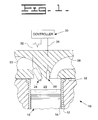
- Fig. 1 identifies a typical internal combustion engine 10 including a tubular cylinder liner 12 which forms a cylinder 14.
- Engine 10 is representative of a wide variety of internal combustion engines including both single cylinder engines and multiple cylinder engines which use a wide variety of fuels including, gasoline, diesel fuel, alcohols and methane, to name just a few types of engines with which the present invention is usable.
- Cylinder 14 of engine 10 contains a piston 16 reciprocally movable therein in the usual manner, in connection with a crankshaft of the engine (not shown).
- Engine 10 further includes a head 18 enclosing one end of cylinder 14 to form a combustion chamber 20.
- Head 18 of engine 10 includes an intake port 22 extending therethrough in communication with combustion chamber 20 for the passage of an air fuel mixture into the combustion chamber, a conventional spark plug 24 for igniting the air fuel mixture, a conventional combustion sensor 26 for sensing combustion in the combustion chamber, and an exhaust port 28 extending through head 18 in communication with the combustion chamber for exhausting the products of combustion therefrom.
- Engine 10 includes a controller 30 for controlling the air fuel mixture delivered to combustion chamber 20 and delivery of ignition effecting signals to spark plug 24 via wire 32.
- Combustion sensor 26 is an ion probe operable to produce a combustion signal when a flame front from combustion in combustion chamber 20 passes by the probe.
- the combustion signal has a combustion quality indicative voltage level and is communicated to controller 30 over a conductive path 34 which typically includes a wiring harness.
- conductive path 34 is of conventional construction and can include one or more lengths of wire which can be connected together and with combustion sensor 26 and controller 30 by conventional electrical connectors or in any other conventional manner.
- Fault conditions that can occur along conductive path 34 typically include corruption or infiltration by water, oil and/or engine coolants through insulating material that surrounds the wire or connector (not shown) so as to alter electrical signals communicated along the path. Also, conductive path 34 can become short circuited or open circuited so as to also alter or even eliminate the electrical signal. As a result, the actual signal, if any, sensed by the controller may be different than that originally produced by the combustion sensor. The controller typically utilizes the combustion sensor signal as one of the parameters for adjusting such other parameters as the air fuel mixture, and thus, any error in the combustion sensor signal sensed by the controller can result in improper engine operation.
- combustion signal produced by combustion sensor 26 such signal has a variable voltage level, that is, a signal having a higher voltage level is produced when better flame propagation characteristics are sensed by the sensor, and a signal having a lower voltage level is produced when worse conditions are sensed, for instance, a misfire in the combustion chamber 20.
- a fault is present on conductive path 34, such as, due to corruption of the conductive path by water, oil and/or coolant, or, a short circuit
- a high level voltage signal produced by combustion sensor 26 indicative of good combustion conditions in combustion chamber 20 can be decreased by passage along the corrupted wiring harness such that the voltage level sensed by controller 30 is substantially lower.
- controller 30 is operable to sense the voltage level on the conductive path and compare such sensed levels with a predetermined value representative of the upper threshold value for corruption of conductive path 34 and/or a short circuit therein.
- the upper threshold value for any given engine type may be determined through engine testing. During engine operation, if a sensed voltage level is below this predetermined value, the controller 30 will correctly diagnose the problem as a conductive path fault condition and can operate accordingly. For instance, the controller can continue to operate the affected cylinder, produce a diagnostic signal indicative of the problem, store the signal for later retrieval, and/or broadcast the signal to an operator display and/or a service tool.
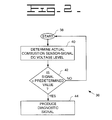
- Fig. 2 shows a high level flow diagram 36 illustrating the operation of controller 30 for detecting a fault condition of conductive path 34.
- the controller 30 begins at starting block 38 where the controller 30 is operable to monitor the conductive path 34 so as to sense the voltage level thereon.
- controller 30 determines the combustion sensor signal DC voltage level by sensing the voltage on the conductive path 34.
- controller 30 compares the sensed voltage level to a predetermined value representative of an upper threshold value for a fault condition on conductive path 34.
- controller 30 If the sensed voltage level is found to be less than the predetermined value, a fault condition of the conductive path 34 is indicated, and controller 30 will proceed to produce a diagnostic signal representative of the fault condition as shown by block 44. On the other hand, if the signal is not less than the predetermined value, controller 30 will return to the start condition represented by block 38, wherein the controller will monitor conductive path 34 for the next combustion signal.
- controller 30 is able to differentiate a low voltage level combustion signal due to a fault of the conductive path from one indicative of a misfire or other poor combustion condition, needless engine adjustments such as termination of combustion in the affected cylinder can be eliminated.
- the diagnostic signal can be stored in memory either contained in the controller itself or external thereto, supplied to a service tool, and/or broadcast to an operator display, such that the fault can be more rapidly and accurately diagnosed and corrected.
- the present diagnostic apparatus and method for a combustion sensor feedback system has applicability for a wide variety of internal combustion engine applications, including vehicular applications, as well as industrial, gas compression, electric power generation, and co-generation applications, using a wide range of fuels. Operational objects for all such engines include high output, low emissions, high thermal efficiency, and precise control of engine operating parameters.
- the present diagnostic apparatus and method help achieve these objectives by enabling an electronic engine controller to distinguish combustion problems such as misfire and the like from fault conditions in a conductive path for communicating signals from a combustion sensor to the controller, to avoid needlessly terminating combustion in a cylinder. Such fault detection and engine control results in improved overall engine operation without significant added costs or complexity.
Landscapes
- Engineering & Computer Science (AREA)
- Chemical & Material Sciences (AREA)
- Combustion & Propulsion (AREA)
- Mechanical Engineering (AREA)
- General Engineering & Computer Science (AREA)
- Combined Controls Of Internal Combustion Engines (AREA)
- Testing Of Engines (AREA)
- Ignition Installations For Internal Combustion Engines (AREA)
Applications Claiming Priority (2)
| Application Number | Priority Date | Filing Date | Title |
|---|---|---|---|
| US93258097A | 1997-09-17 | 1997-09-17 | |
| US932580 | 1997-09-17 |
Publications (1)
| Publication Number | Publication Date |
|---|---|
| EP0903486A2 true EP0903486A2 (fr) | 1999-03-24 |
Family
ID=25462536
Family Applications (1)
| Application Number | Title | Priority Date | Filing Date |
|---|---|---|---|
| EP19980306229 Withdrawn EP0903486A2 (fr) | 1997-09-17 | 1998-08-04 | Dispositif et procédé diagnostique du capteur dans un système de régulation à contre-réaction de la combustion |
Country Status (2)
| Country | Link |
|---|---|
| EP (1) | EP0903486A2 (fr) |
| JP (1) | JPH11148418A (fr) |
Citations (4)
| Publication number | Priority date | Publication date | Assignee | Title |
|---|---|---|---|---|
| US5036669A (en) | 1989-12-26 | 1991-08-06 | Caterpillar Inc. | Apparatus and method for controlling the air/fuel ratio of an internal combustion engine |
| US5041980A (en) | 1990-06-04 | 1991-08-20 | Caterpillar Inc. | Method and apparatus for producing fault signals responsive to malfunctions in individual engine cylinders |
| US5392641A (en) | 1993-03-08 | 1995-02-28 | Chrysler Corporation | Ionization misfire detection apparatus and method for an internal combustion engine |
| GB2282221A (en) | 1993-09-22 | 1995-03-29 | Rolls Royce Plc | A flame detector |
-
1998
- 1998-08-04 EP EP19980306229 patent/EP0903486A2/fr not_active Withdrawn
- 1998-09-16 JP JP26170498A patent/JPH11148418A/ja not_active Withdrawn
Patent Citations (4)
| Publication number | Priority date | Publication date | Assignee | Title |
|---|---|---|---|---|
| US5036669A (en) | 1989-12-26 | 1991-08-06 | Caterpillar Inc. | Apparatus and method for controlling the air/fuel ratio of an internal combustion engine |
| US5041980A (en) | 1990-06-04 | 1991-08-20 | Caterpillar Inc. | Method and apparatus for producing fault signals responsive to malfunctions in individual engine cylinders |
| US5392641A (en) | 1993-03-08 | 1995-02-28 | Chrysler Corporation | Ionization misfire detection apparatus and method for an internal combustion engine |
| GB2282221A (en) | 1993-09-22 | 1995-03-29 | Rolls Royce Plc | A flame detector |
Also Published As
| Publication number | Publication date |
|---|---|
| JPH11148418A (ja) | 1999-06-02 |
Similar Documents
| Publication | Publication Date | Title |
|---|---|---|
| US5396176A (en) | Combustion condition diagnosis utilizing multiple sampling of ionic current | |
| US20070079817A1 (en) | Method and apparatus for controlling exhaust gas recirculation and start of combustion in reciprocating compression ignition engines with an ignition system with ionization measurement | |
| US5046470A (en) | Method of and device for monitoring combustion in a spark ignition internal combustion engine | |
| US5283527A (en) | Methods and apparatus for detecting short circuited secondary coil winding via monitoring primary coil winding | |
| US10900461B2 (en) | System and method for monitoring an ignition system | |
| US5505077A (en) | Method for detecting misfiring in an internal combustion engine | |
| US6439029B2 (en) | Method of detecting a knock in an internal combustion engine by means of ionic current | |
| US6155241A (en) | Method for identifying knocking combustion in an internal combustion engine with an alternating current ignition system | |
| US7062373B2 (en) | Misfire detection apparatus of internal combustion engine | |
| US6813932B2 (en) | Misfire detection device for internal combustion engine | |
| US8438906B2 (en) | Apparatus and method for the detection of knocking combustion | |
| US6211680B1 (en) | Process and apparatus for recognizing ignition failures in an internal-combustion engine having two spark plugs per cylinder | |
| US5327867A (en) | Misfire-detecting system for internal combustion engines | |
| US6691555B2 (en) | Firing state discrimination system for internal combustion engines | |
| JP2008298782A (ja) | 燃焼評価方法 | |
| EP0903486A2 (fr) | Dispositif et procédé diagnostique du capteur dans un système de régulation à contre-réaction de la combustion | |
| CN101886601A (zh) | 用于控制内燃机中的爆震的方法 | |
| US5987373A (en) | Diagnostic apparatus and method for detecting noise on a combustion sensor feedback system | |
| JPH04314970A (ja) | 火花点火機関の失火検出装置 | |
| US5983866A (en) | Diagnostic apparatus and method for a combustion sensor feedback system | |
| JPS6136777Y2 (fr) | ||
| JPH07119533A (ja) | 内燃機関の燃焼状態検出装置 | |
| US6945230B2 (en) | Method for eliminating detonation in an engine | |
| JP2023009575A (ja) | 火花点火式内燃機関用の判定装置 | |
| JPH0826843B2 (ja) | 火花点火機関の二次電圧検出器 |
Legal Events
| Date | Code | Title | Description |
|---|---|---|---|
| PUAI | Public reference made under article 153(3) epc to a published international application that has entered the european phase |
Free format text: ORIGINAL CODE: 0009012 |
|
| AK | Designated contracting states |
Kind code of ref document: A2 Designated state(s): AT BE CH CY DE DK ES FI FR GB GR IE IT LI LU MC NL PT SE |
|
| AX | Request for extension of the european patent |
Free format text: AL;LT;LV;MK;RO;SI |
|
| STAA | Information on the status of an ep patent application or granted ep patent |
Free format text: STATUS: THE APPLICATION HAS BEEN WITHDRAWN |
|
| 18W | Application withdrawn |
Withdrawal date: 19990322 |