EP0903433A2 - An improved belt transmission, particularly for laundry driers and washing machines - Google Patents
An improved belt transmission, particularly for laundry driers and washing machines Download PDFInfo
- Publication number
- EP0903433A2 EP0903433A2 EP98200641A EP98200641A EP0903433A2 EP 0903433 A2 EP0903433 A2 EP 0903433A2 EP 98200641 A EP98200641 A EP 98200641A EP 98200641 A EP98200641 A EP 98200641A EP 0903433 A2 EP0903433 A2 EP 0903433A2
- Authority
- EP
- European Patent Office
- Prior art keywords
- pulley
- belt
- motor
- driving
- belt transmission
- Prior art date
- Legal status (The legal status is an assumption and is not a legal conclusion. Google has not performed a legal analysis and makes no representation as to the accuracy of the status listed.)
- Granted
Links
Images


Classifications
-
- D—TEXTILES; PAPER
- D06—TREATMENT OF TEXTILES OR THE LIKE; LAUNDERING; FLEXIBLE MATERIALS NOT OTHERWISE PROVIDED FOR
- D06F—LAUNDERING, DRYING, IRONING, PRESSING OR FOLDING TEXTILE ARTICLES
- D06F37/00—Details specific to washing machines covered by groups D06F21/00 - D06F25/00
- D06F37/30—Driving arrangements
-
- D—TEXTILES; PAPER
- D06—TREATMENT OF TEXTILES OR THE LIKE; LAUNDERING; FLEXIBLE MATERIALS NOT OTHERWISE PROVIDED FOR
- D06F—LAUNDERING, DRYING, IRONING, PRESSING OR FOLDING TEXTILE ARTICLES
- D06F58/00—Domestic laundry dryers
- D06F58/02—Domestic laundry dryers having dryer drums rotating about a horizontal axis
- D06F58/04—Details
- D06F58/08—Driving arrangements
Definitions
- the present invention relates to an improved belt transmission intended particularly for laundry driers and washing machines but also usable in any situation in which it is necessary to achieve a very high transmission ratio of the order of 50 or more with fairly large inert loads, with motors such as induction motors which have limited starting torque.
- motors such as induction motors which have limited starting torque.
- induction motors possibly with a switchable number of poles in washing machines
- they are preferable to commutator motors which require periodic maintenance.
- the drive is transmitted from the motor shaft to the drying or washing drum by means of a belt transmission.
- the same motor preferably also drives directly the fan which produces a ventilation flow in the drum.
- Efficient ventilation requires a fast speed of rotation of the motor, which is typically an asynchronous motor with two poles, with a nominal rate of rotation of 2800 revolutions/min., whereas the drying drum typically has to rotate at a speed of 50-55 revolutions/min.
- the motor It is therefore necessary for the motor to be over-sized to a certain extent, at considerable cost, in order to reduce losses and to ensure a higher starting torque or, as occurs in some cases, to use commutator motors, variable-reluctance motors, variable-frequency motors, or even so-called “brushless” motors, all of which are much more expensive.
- the bearings supporting the motor shaft and the drive shaft are also over-sized in order to withstand the stresses imposed by the pull of the belt, with consequent increases in cost.
- the belt transmission of the present invention in which a very high transmission ratio is achieved by a driving pulley keyed to the motor shaft and having a diameter larger than that of the motor shaft, a driven pulley constituted, for example, by the drum of a laundry drier, and a floating pulley having a pair of identical circular winding surfaces and a third circular winding surface with a different diameter from that of the pair, a pair of transmission belts wound around the pair of identical circular surfaces and around one of the driving and driven pulleys, and a third transmission belt wound around the third winding surface and around the other of the driving and driven pulleys.
- the ratio between the diameters of the pair of identical circular surfaces and of the third circular surface of the floating pulley which, for example, may be of the order of 3:1, it is possible to use a driving pulley with a diameter larger than that of the motor shaft, for example, of 30 mm and to achieve the desired overall transmission ratio of 50 or more.
- the floating pulley does not require a support axle and is therefore defined as floating since it is kept in position by the opposed pulls of the pair of belts and of the third belt.
- the position of the floating pulley is defined by the symmetrical pulling conditions of the transmission belts and its axis is aligned with the axes of the driving pulley and of the driven pulley and parallel thereto.
- a floating pulley in the belt transmission of the invention in combination with a pulley with a diameter which is variable according to the speed of rotation, which may be the floating pulley itself or one or other of the driving and driven pulleys, renders starting and drive reversal even easier by variation of the transmission ratio in dependence on the speed.
- the transmission belts have to have sufficient resilience to compensate for changes in the length of the path of the belt due to the variable diameter of one of the pulleys or, in equivalent manner, the floating pulley may be biased by resilient restraints to a position in which it is not aligned with the axes of the driving and driven pulleys.
- an intermediate floating transmission pulley permits the use of belts of two different types of specifically suitable length, thickness and bending capacity, for example, a trapezoidal-sectioned belt for the coupling between the washing/drying drum and the floating pulley and a pair of relatively thin, flat or multi-channelled belts for the coupling between the floating pulley and the motor shaft.
- this shows, in frontal section, a known laundry drier constituted by a casing 1 housing a drying drum 2 and a drive motor 3 with a shaft 4 parallel to the axis 2A of the drum and perpendicular to the plane of the drawing.
- the motor 3 which is preferably of the two-pole induction type, drives directly a fan, not shown, and, by means of a belt transmission 5, the drum 2.
- the motor rotates at a nominal speed of 2800 revolutions/minute when it is supplied with a voltage alternating at a frequency of 50Hz, in order to achieve the desired speed of rotation of the drum of 50/55 revolutions/minute, it is necessary for the belt 5 to be wound directly around the periphery of the drum 2 which has a diameter of the order of 55 cm and around the shaft of the motor which has a diameter of the order of 10 mm.
- the angle through which the belt is wound on the shaft 4 is very small, of the order of 90° or a little more, and the belt is subject to considerable bending stress with a radius or curvature of the order of 5 mm.
- the coupling between the drum 2 and the motor 3 is formed by a belt transmission constituted by three belts and by a floating pulley 6.
- floating pulley is meant a pulley which is not engaged on a support axle in a fixed and predetermined position but which is free to move according to the pull exerted by the belts which are wound around the pulley.
- the pulley 6 has a first circular surface 7 for the winding of a first belt 5, flanked axially on opposite sides by two circular surfaces 8, 9 for the winding of two identical belts 10 and 11.
- the first surface 7 has a diameter of the order of 30 mm and the pair of circular surfaces 8, 9 has a diameter of the order of 90 mm.
- the generally circular winding surfaces 7, 8, 9 may be either cylindrical or grooved, or may even have a recessed trapezoidal shape, according to the type of belt to be used.
- the larger-diameter surfaces 8, 9 may have restraining shoulders for preventing axial displacement of the belts relative to the pulley.
- the first belt 5 is wound around the periphery of the drum 2 and around the first surface 7 of the pulley 6.
- the other two belts 10, 11 are wound, respectively, around the other circular surfaces 8, 9 of the pulley 6 and around a hub 12 keyed to the motor shaft 4.
- the axis of the pulley 6 In rest conditions, that is, in the absence of transmitted torque, the axis of the pulley 6 is parallel to and aligned with the axis of the motor shaft 4 and the axis of the drum, that is, in the plane defined thereby, by virtue of the symmetrical pull of the belts.
- Figure 4 shows the pulley 6 in continuous outline in the rest position.
- the changes in the position of the pulley have the effect of introducing into the transmission a resilient component which temporarily disconnects the motor shaft from the driven member to a certain extent.
- This type of transmission with a floating pulley can therefore advantageously be used not only for laundry dryers but also for washing machines in which, as is known, the washing is carried out with periodic reversal of the sense of rotation of a washing drum.
- the transmission system described is suitable for the development of a transmission with a ratio which is variable in dependence on speed, making it even easier to start and reverse the movement of a drive system with an induction motor.
- the floating pulley 14 has a first winding surface 15 for a trapezoidal-sectioned belt, the diameter of this surface being variable in dependence on speed, flanked by two identical circular surfaces 16, 17 of larger diameter.
- a first belt 18, in this embodiment of trapezoidal section, is wound around the first surface 15 and around the periphery of the drum 2, coupling them kinematically.
- a pair of belts 19, 20 is wound around the two circular surfaces 16, 17 and around a hub 21 keyed to the shaft 4 of the motor 3.
- a belt transmission with a variable transmission ratio is thus formed.
- the floating pulley 14 is advantageously supported by a
- floating axle 22 biased resiliently by a spring 23 towards a position removed from the plane defined by the axis of the motor shaft and by the axis of the drum.
- this provides the belts with a path the length of which is independent of the variable diameter of the fist winding surface 15.
- the axis of the floating pulley may be aligned with the axes of the motor shaft and of the drying drum.
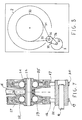
- Figure 6 shows an embodiment of a floating pulley with a variable diameter in a detailed diametral section.
- the pulley is constituted by a hub 24 having a conical flange 25 terminating at its periphery in a cylindrical winding surface for the belt 20.
- a conical flange 26 is mounted for sliding axially on the hub 24, facing the flange 25.
- the belt 18 is fitted between the two flanges 25, 26 and, as a result of the pull imparted, tends to keep the two flanges spaced apart.
- a third conical flange 27 is fixed firmly to the hub 24 and terminates at its periphery in a cylindrical winding surface for the belt 19.
- the two flanges 26 and 27 form an annular housing for a plurality of balls 28, 29.
- the width of the housing in the axial direction decreases towards the periphery of the pulley.
- the balls 28, 29 tend to move away from the axis of rotation as a result of the centrifugal effect and tend to move the flange 26 towards the flange 25, overcoming the axial thrust exerted by the belt 18 on the flange 26.
- the trapezoidal-sectioned belt 18 is forced to be wedged between the flanges along a winding surface of larger diameter and hence with a higher transmission ratio.
- the ratio varies with variations in the speed of rotation and increases therewith, although not proportionally.
- the transmission system thus has an overall transmission ratio of 100-150 upon starting, permitting easy starting, decreasing to a value of 50 in running conditions.
- the cylindrical surfaces 16, 17 for the winding of the belts 19, 20 advantageously extend axially to permit an equal relative axial displacement of the belts.
- the spring 23 acts on the axle 22 of the floating pulley by means of a stirrup or fork, not shown, to keep the axle 22 parallel to the axle of the motor shaft and of the drying drum.
- the floating pulley adopts the shape of a cylindrical element extended axially at its opposite ends by two cylindrical elements of smaller diameter.
- the washing drum 2 has a driving pulley 30 with a diameter typically of 278 mm.
- a motor 3 is coupled to the pulley 30 by means of a first transmission belt which is wound around a first circular surface 33 with a diameter variable between approximately 45 mm at low speeds of rotation and approximately 70 mm at high speeds of rotation, of a variable-ratio floating pulley 34.
- the belt 31, which is trapezoidal, may be extensible.
- the floating pulley 34 of the type already described has a pair of circular surfaces 35 with diameters of about 45 mm.
- a pair of belts 36 preferably of the POLY-V type, is wound around the circular surfaces 35 and around a shaft or hub 37 rotated by the motor 31.
- the solution commonly used provides for direct coupling of the pulley 30 to the motor 31 by means of a trapezoidal-sectioned belt and a hub with a variable diameter keyed to the motor shaft.
- the maximum diameter of the hub is about 60 mm and the minimum diameter which is imposed by the use of a trapezoidal belt, may be no less than 46 mm, which necessitates the use of a speed of rotation for washing of about 75 revolutions/minute with a consequent reduction in washing efficiency.
- commutator motors are used, and are coupled to the pulley 30 by means of a multi-channelled belt which excludes the possibility of the use of a variable-diameter hub.
Landscapes
- Engineering & Computer Science (AREA)
- Textile Engineering (AREA)
- Devices For Conveying Motion By Means Of Endless Flexible Members (AREA)
- Detail Structures Of Washing Machines And Dryers (AREA)
- Cleaning By Liquid Or Steam (AREA)
- Main Body Construction Of Washing Machines And Laundry Dryers (AREA)
Abstract
Description
Claims (8)
- A belt transmission comprising a driving pulley (12) keyed to a motor shaft (4) or constituted by the motor shaft (4), a driven pulley (2) keyed to a driven shaft (2A), and a transmission belt (5),
characterized in that it comprisesa floating pulley (6,14) with a first circular surface (7,15) for the winding of the belt (5,18), a pair of identical circular surfaces (8,9,16,17) for the winding of belts (10,11,19,20), coaxial with the first surface (7,15) and arranged axially one on each side of the first surface (7,15), and a pair of identical transmission belts (10,11,19,20) wound around the pair of identical circular surfaces (8,9,16,17) of the floating pulley (6,14) and around one of the driving (12) and driven pulleys (2), respectively, the transmission belt (5,18) coupling the floating pulley (6,14) to the other of the driving (12) and driven pulleys (2). - A belt transmission according to Claim 1, in which the floating pulley (6) is shaped like a reel, the first winding surface (7) being the channel of the reel and the pair of winding surfaces (8,9) being formed by the peripheral surfaces of lateral flanges of the reel.
- A belt transmission according to Claim 1 or Claim 2, comprising means (23) for biasing the floating pulley resiliently to a rest position.
- A belt transmission according to the preceding claims in which one of the driving pulley and the floating pulley is a pulley (14) with a diameter which is variable in dependence on the speed of rotation in order to vary the transmission ratio of the belt transmission (18).
- A belt transmission according to Claim 4, in which the variable-diameter pulley is structurally axially symmetrical.
- A laundry drier comprising an induction motor for driving a rotary drying drum and a fan, incorporating a belt transmission according to the preceding claims for coupling the rotary drum to the motor.
- A washing machine comprising an induction motor for driving a washing drum and incorporating a belt transmission according to the preceding claims for coupling the motor to a washing drum.
- A washing machine comprising a variable-speed commutator motor or an equivalent motor and incorporating a belt transmission according to the preceding claims for coupling the motor to a washing drum.
Applications Claiming Priority (2)
| Application Number | Priority Date | Filing Date | Title |
|---|---|---|---|
| ITMI970670U | 1997-09-18 | ||
| IT1997MI000670U IT237916Y1 (en) | 1997-09-18 | 1997-09-18 | DRIVE BELT TRANSMISSION, IN PARTICULAR DRYER AND WASHING MACHINE |
Publications (3)
| Publication Number | Publication Date |
|---|---|
| EP0903433A2 true EP0903433A2 (en) | 1999-03-24 |
| EP0903433A3 EP0903433A3 (en) | 1999-07-21 |
| EP0903433B1 EP0903433B1 (en) | 2003-09-10 |
Family
ID=11376571
Family Applications (1)
| Application Number | Title | Priority Date | Filing Date |
|---|---|---|---|
| EP98200641A Expired - Lifetime EP0903433B1 (en) | 1997-09-18 | 1998-03-02 | An improved belt transmission, particularly for laundry driers and washing machines |
Country Status (2)
| Country | Link |
|---|---|
| EP (1) | EP0903433B1 (en) |
| IT (1) | IT237916Y1 (en) |
Cited By (4)
| Publication number | Priority date | Publication date | Assignee | Title |
|---|---|---|---|---|
| BE1015494A3 (en) * | 2001-12-07 | 2005-05-03 | Hanning Elektro Werke | Drier. |
| EP1811075A1 (en) * | 2006-01-23 | 2007-07-25 | BSH Bosch und Siemens Hausgeräte GmbH | Clamping device for a gear and pinion drive of a domestic clothes dryer |
| KR20120014487A (en) * | 2010-08-09 | 2012-02-17 | 엘지전자 주식회사 | Laundry treatment equipment |
| US9809917B2 (en) | 2010-08-09 | 2017-11-07 | Lg Electronics Inc. | Apparatus for treating laundry |
Families Citing this family (1)
| Publication number | Priority date | Publication date | Assignee | Title |
|---|---|---|---|---|
| DE202018102326U1 (en) * | 2018-04-25 | 2018-11-06 | Peter Lutz | Transmission gear and wind turbine and electric drive for vehicles with such a transmission gear |
Family Cites Families (6)
| Publication number | Priority date | Publication date | Assignee | Title |
|---|---|---|---|---|
| US2337586A (en) * | 1942-03-25 | 1943-12-28 | Bendix Home Appliances Inc | Belt transmission mechanism |
| US2506516A (en) * | 1945-09-19 | 1950-05-02 | Hamilton Mfg Co | Laundry drier |
| US2942447A (en) * | 1957-08-07 | 1960-06-28 | Whirlpool Co | Clothes washing and extracting machine |
| FR1352845A (en) * | 1962-10-31 | 1964-02-21 | Improvements to horizontal drum washing machines | |
| JPS60234160A (en) * | 1984-05-07 | 1985-11-20 | Hitachi Seiko Ltd | Belt drive mechanism |
| DE4438425B4 (en) * | 1994-10-27 | 2006-10-26 | BSH Bosch und Siemens Hausgeräte GmbH | Drive device for a household tumble dryer |
-
1997
- 1997-09-18 IT IT1997MI000670U patent/IT237916Y1/en active IP Right Grant
-
1998
- 1998-03-02 EP EP98200641A patent/EP0903433B1/en not_active Expired - Lifetime
Cited By (4)
| Publication number | Priority date | Publication date | Assignee | Title |
|---|---|---|---|---|
| BE1015494A3 (en) * | 2001-12-07 | 2005-05-03 | Hanning Elektro Werke | Drier. |
| EP1811075A1 (en) * | 2006-01-23 | 2007-07-25 | BSH Bosch und Siemens Hausgeräte GmbH | Clamping device for a gear and pinion drive of a domestic clothes dryer |
| KR20120014487A (en) * | 2010-08-09 | 2012-02-17 | 엘지전자 주식회사 | Laundry treatment equipment |
| US9809917B2 (en) | 2010-08-09 | 2017-11-07 | Lg Electronics Inc. | Apparatus for treating laundry |
Also Published As
| Publication number | Publication date |
|---|---|
| ITMI970670U1 (en) | 1999-03-18 |
| IT237916Y1 (en) | 2000-09-29 |
| EP0903433A3 (en) | 1999-07-21 |
| EP0903433B1 (en) | 2003-09-10 |
Similar Documents
| Publication | Publication Date | Title |
|---|---|---|
| US7712592B2 (en) | Spring travel limiter for overrunning alternator decoupler | |
| JP4131540B2 (en) | Horizontal drum washing machine | |
| JP5608293B2 (en) | Isolating decoupler | |
| US5676225A (en) | Belt transmission device for engine auxiliaries | |
| EP1055765A1 (en) | Drum type washing machine with aligning structure for rotor and stator of drive motor | |
| KR960008120A (en) | Belt transmission method and belt transmission device | |
| KR20050039832A (en) | Overrunning alternator decoupler pulley with bare wire spring and grease lubrication | |
| US2337586A (en) | Belt transmission mechanism | |
| US20040163429A1 (en) | Dual-motor drum-type washing machine | |
| US5730269A (en) | Centrifugal friction clutch | |
| EP0903433B1 (en) | An improved belt transmission, particularly for laundry driers and washing machines | |
| US4018096A (en) | Slipping belt clutch | |
| US4019397A (en) | Belt drive mechanism | |
| US3584482A (en) | Clothes washer having an oscillating and spinning drive mechanism | |
| US3866731A (en) | Speed responsive clutch | |
| US4743221A (en) | Centrifugal clutch belt tightening assembly | |
| GB1561775A (en) | Speed-changing devices in particular for spin driying in laundry washing machines which are equipped with a pole chaange motor | |
| GB2137732A (en) | Speed equalizing couplings | |
| EP0781906B1 (en) | Apparatus for driving alternator of engine, and alternator for engine accessoires used therefor | |
| JP4788617B2 (en) | Pulley unit | |
| JP2501267Y2 (en) | Pre-twisting device for twisting machine | |
| KR100352965B1 (en) | automatic transmission pulley | |
| KR930003703Y1 (en) | Roller-clutch supporter for auto-washer | |
| JPWO1996008642A1 (en) | Engine alternator drive device and engine accessory alternator used therefor | |
| SU369316A1 (en) | ALL-UNION I |
Legal Events
| Date | Code | Title | Description |
|---|---|---|---|
| PUAI | Public reference made under article 153(3) epc to a published international application that has entered the european phase |
Free format text: ORIGINAL CODE: 0009012 |
|
| AK | Designated contracting states |
Kind code of ref document: A2 Designated state(s): FR GB IT |
|
| AX | Request for extension of the european patent |
Free format text: AL;LT;LV;MK;RO;SI |
|
| PUAL | Search report despatched |
Free format text: ORIGINAL CODE: 0009013 |
|
| AK | Designated contracting states |
Kind code of ref document: A3 Designated state(s): AT BE CH DE DK ES FI FR GB GR IE IT LI LU MC NL PT SE |
|
| AX | Request for extension of the european patent |
Free format text: AL;LT;LV;MK;RO;SI |
|
| RIC1 | Information provided on ipc code assigned before grant |
Free format text: 6D 06F 58/08 A, 6D 06F 37/30 B, 6F 16H 7/02 B |
|
| 17P | Request for examination filed |
Effective date: 19990827 |
|
| AKX | Designation fees paid |
Free format text: FR GB IT |
|
| REG | Reference to a national code |
Ref country code: DE Ref legal event code: 8566 |
|
| 17Q | First examination report despatched |
Effective date: 20010907 |
|
| GRAG | Despatch of communication of intention to grant |
Free format text: ORIGINAL CODE: EPIDOS AGRA |
|
| GRAG | Despatch of communication of intention to grant |
Free format text: ORIGINAL CODE: EPIDOS AGRA |
|
| GRAH | Despatch of communication of intention to grant a patent |
Free format text: ORIGINAL CODE: EPIDOS IGRA |
|
| GRAH | Despatch of communication of intention to grant a patent |
Free format text: ORIGINAL CODE: EPIDOS IGRA |
|
| GRAA | (expected) grant |
Free format text: ORIGINAL CODE: 0009210 |
|
| AK | Designated contracting states |
Kind code of ref document: B1 Designated state(s): FR GB IT |
|
| REG | Reference to a national code |
Ref country code: GB Ref legal event code: FG4D |
|
| ET | Fr: translation filed | ||
| ET1 | Fr: translation filed ** revision of the translation of the patent or the claims | ||
| PLBE | No opposition filed within time limit |
Free format text: ORIGINAL CODE: 0009261 |
|
| STAA | Information on the status of an ep patent application or granted ep patent |
Free format text: STATUS: NO OPPOSITION FILED WITHIN TIME LIMIT |
|
| 26N | No opposition filed |
Effective date: 20040614 |
|
| PGFP | Annual fee paid to national office [announced via postgrant information from national office to epo] |
Ref country code: GB Payment date: 20090325 Year of fee payment: 12 |
|
| PGFP | Annual fee paid to national office [announced via postgrant information from national office to epo] |
Ref country code: IT Payment date: 20090312 Year of fee payment: 12 Ref country code: FR Payment date: 20090331 Year of fee payment: 12 |
|
| GBPC | Gb: european patent ceased through non-payment of renewal fee |
Effective date: 20100302 |
|
| REG | Reference to a national code |
Ref country code: FR Ref legal event code: ST Effective date: 20101130 |
|
| PG25 | Lapsed in a contracting state [announced via postgrant information from national office to epo] |
Ref country code: FR Free format text: LAPSE BECAUSE OF NON-PAYMENT OF DUE FEES Effective date: 20100331 |
|
| PG25 | Lapsed in a contracting state [announced via postgrant information from national office to epo] |
Ref country code: IT Free format text: LAPSE BECAUSE OF NON-PAYMENT OF DUE FEES Effective date: 20100302 Ref country code: GB Free format text: LAPSE BECAUSE OF NON-PAYMENT OF DUE FEES Effective date: 20100302 |