EP0902944B1 - Texturiertes magnetisches aufzeichnungsmedium mit übergangszone - Google Patents
Texturiertes magnetisches aufzeichnungsmedium mit übergangszone Download PDFInfo
- Publication number
- EP0902944B1 EP0902944B1 EP96918269A EP96918269A EP0902944B1 EP 0902944 B1 EP0902944 B1 EP 0902944B1 EP 96918269 A EP96918269 A EP 96918269A EP 96918269 A EP96918269 A EP 96918269A EP 0902944 B1 EP0902944 B1 EP 0902944B1
- Authority
- EP
- European Patent Office
- Prior art keywords
- zone
- textured
- landing
- protrusions
- magnetic recording
- Prior art date
- Legal status (The legal status is an assumption and is not a legal conclusion. Google has not performed a legal analysis and makes no representation as to the accuracy of the status listed.)
- Expired - Lifetime
Links
- 230000007704 transition Effects 0.000 title claims description 42
- 239000000758 substrate Substances 0.000 claims description 37
- 238000000034 method Methods 0.000 claims description 27
- 230000002250 progressing effect Effects 0.000 claims description 10
- 230000001681 protective effect Effects 0.000 claims description 8
- 238000004519 manufacturing process Methods 0.000 claims description 7
- 239000000314 lubricant Substances 0.000 claims description 5
- 230000003746 surface roughness Effects 0.000 claims description 5
- 230000003287 optical effect Effects 0.000 description 15
- 239000002178 crystalline material Substances 0.000 description 13
- 239000011521 glass Substances 0.000 description 10
- 239000011651 chromium Substances 0.000 description 8
- 239000002241 glass-ceramic Substances 0.000 description 8
- 229910045601 alloy Inorganic materials 0.000 description 7
- 239000000956 alloy Substances 0.000 description 7
- 230000007423 decrease Effects 0.000 description 5
- 229910000838 Al alloy Inorganic materials 0.000 description 4
- OKTJSMMVPCPJKN-UHFFFAOYSA-N Carbon Chemical compound [C] OKTJSMMVPCPJKN-UHFFFAOYSA-N 0.000 description 4
- 229910000599 Cr alloy Inorganic materials 0.000 description 4
- 229910052799 carbon Inorganic materials 0.000 description 4
- 229910052804 chromium Inorganic materials 0.000 description 4
- 238000005498 polishing Methods 0.000 description 4
- VYZAMTAEIAYCRO-UHFFFAOYSA-N Chromium Chemical compound [Cr] VYZAMTAEIAYCRO-UHFFFAOYSA-N 0.000 description 3
- 229910052782 aluminium Inorganic materials 0.000 description 3
- SNAAJJQQZSMGQD-UHFFFAOYSA-N aluminum magnesium Chemical compound [Mg].[Al] SNAAJJQQZSMGQD-UHFFFAOYSA-N 0.000 description 3
- 230000015572 biosynthetic process Effects 0.000 description 3
- 239000013078 crystal Substances 0.000 description 3
- 239000010409 thin film Substances 0.000 description 3
- XUIMIQQOPSSXEZ-UHFFFAOYSA-N Silicon Chemical compound [Si] XUIMIQQOPSSXEZ-UHFFFAOYSA-N 0.000 description 2
- 239000000788 chromium alloy Substances 0.000 description 2
- 229910017052 cobalt Inorganic materials 0.000 description 2
- 239000010941 cobalt Substances 0.000 description 2
- GUTLYIVDDKVIGB-UHFFFAOYSA-N cobalt atom Chemical compound [Co] GUTLYIVDDKVIGB-UHFFFAOYSA-N 0.000 description 2
- KPLQYGBQNPPQGA-UHFFFAOYSA-N cobalt samarium Chemical compound [Co].[Sm] KPLQYGBQNPPQGA-UHFFFAOYSA-N 0.000 description 2
- 238000000151 deposition Methods 0.000 description 2
- 239000006112 glass ceramic composition Substances 0.000 description 2
- 238000012986 modification Methods 0.000 description 2
- 230000004048 modification Effects 0.000 description 2
- 238000005457 optimization Methods 0.000 description 2
- 238000007747 plating Methods 0.000 description 2
- 229910052710 silicon Inorganic materials 0.000 description 2
- 239000010703 silicon Substances 0.000 description 2
- 238000004544 sputter deposition Methods 0.000 description 2
- 238000012876 topography Methods 0.000 description 2
- PFNQVRZLDWYSCW-UHFFFAOYSA-N (fluoren-9-ylideneamino) n-naphthalen-1-ylcarbamate Chemical compound C12=CC=CC=C2C2=CC=CC=C2C1=NOC(=O)NC1=CC=CC2=CC=CC=C12 PFNQVRZLDWYSCW-UHFFFAOYSA-N 0.000 description 1
- 229910021532 Calcite Inorganic materials 0.000 description 1
- 229910000531 Co alloy Inorganic materials 0.000 description 1
- 229910018104 Ni-P Inorganic materials 0.000 description 1
- 229910018536 Ni—P Inorganic materials 0.000 description 1
- 229910001080 W alloy Inorganic materials 0.000 description 1
- LMHKOBXLQXJSOU-UHFFFAOYSA-N [Co].[Ni].[Pt] Chemical compound [Co].[Ni].[Pt] LMHKOBXLQXJSOU-UHFFFAOYSA-N 0.000 description 1
- HDCBUBMMAVSYSI-UHFFFAOYSA-N [Cr].[Co].[Ni].[Pt] Chemical compound [Cr].[Co].[Ni].[Pt] HDCBUBMMAVSYSI-UHFFFAOYSA-N 0.000 description 1
- DTJAVSFDAWLDHQ-UHFFFAOYSA-N [Cr].[Co].[Pt] Chemical compound [Cr].[Co].[Pt] DTJAVSFDAWLDHQ-UHFFFAOYSA-N 0.000 description 1
- TZVJRPRFJIXRGV-UHFFFAOYSA-N [Cr].[Co].[Ta] Chemical compound [Cr].[Co].[Ta] TZVJRPRFJIXRGV-UHFFFAOYSA-N 0.000 description 1
- UGGYKLULVSLVBW-UHFFFAOYSA-N [Pt].[B].[Cr].[Co] Chemical compound [Pt].[B].[Cr].[Co] UGGYKLULVSLVBW-UHFFFAOYSA-N 0.000 description 1
- 230000002411 adverse Effects 0.000 description 1
- XAGFODPZIPBFFR-UHFFFAOYSA-N aluminium Chemical compound [Al] XAGFODPZIPBFFR-UHFFFAOYSA-N 0.000 description 1
- SZMZREIADCOWQA-UHFFFAOYSA-N chromium cobalt nickel Chemical compound [Cr].[Co].[Ni] SZMZREIADCOWQA-UHFFFAOYSA-N 0.000 description 1
- QXWGVGIOMAUVTC-UHFFFAOYSA-N chromium cobalt platinum tantalum Chemical compound [Cr][Pt][Co][Ta] QXWGVGIOMAUVTC-UHFFFAOYSA-N 0.000 description 1
- LOAVMVZZMOBPDK-UHFFFAOYSA-N chromium cobalt samarium Chemical compound [Cr][Sm][Co] LOAVMVZZMOBPDK-UHFFFAOYSA-N 0.000 description 1
- UMUXBDSQTCDPJZ-UHFFFAOYSA-N chromium titanium Chemical compound [Ti].[Cr] UMUXBDSQTCDPJZ-UHFFFAOYSA-N 0.000 description 1
- HBXWYZMULLEJSG-UHFFFAOYSA-N chromium vanadium Chemical compound [V][Cr][V][Cr] HBXWYZMULLEJSG-UHFFFAOYSA-N 0.000 description 1
- 239000011248 coating agent Substances 0.000 description 1
- 238000000576 coating method Methods 0.000 description 1
- 239000010952 cobalt-chrome Substances 0.000 description 1
- 238000007796 conventional method Methods 0.000 description 1
- 125000004122 cyclic group Chemical group 0.000 description 1
- 238000013500 data storage Methods 0.000 description 1
- 230000003247 decreasing effect Effects 0.000 description 1
- 230000008021 deposition Effects 0.000 description 1
- 230000000694 effects Effects 0.000 description 1
- 230000001747 exhibiting effect Effects 0.000 description 1
- 230000006872 improvement Effects 0.000 description 1
- 229910001004 magnetic alloy Inorganic materials 0.000 description 1
- 238000012423 maintenance Methods 0.000 description 1
- 230000005499 meniscus Effects 0.000 description 1
- 230000010287 polarization Effects 0.000 description 1
- 238000003825 pressing Methods 0.000 description 1
- 230000008569 process Effects 0.000 description 1
- 239000010453 quartz Substances 0.000 description 1
- GGYFMLJDMAMTAB-UHFFFAOYSA-N selanylidenelead Chemical compound [Pb]=[Se] GGYFMLJDMAMTAB-UHFFFAOYSA-N 0.000 description 1
- VYPSYNLAJGMNEJ-UHFFFAOYSA-N silicon dioxide Inorganic materials O=[Si]=O VYPSYNLAJGMNEJ-UHFFFAOYSA-N 0.000 description 1
- 238000003860 storage Methods 0.000 description 1
- WFKWXMTUELFFGS-UHFFFAOYSA-N tungsten Chemical compound [W] WFKWXMTUELFFGS-UHFFFAOYSA-N 0.000 description 1
- 229910052721 tungsten Inorganic materials 0.000 description 1
- 239000010937 tungsten Substances 0.000 description 1
Images


Classifications
-
- G—PHYSICS
- G11—INFORMATION STORAGE
- G11B—INFORMATION STORAGE BASED ON RELATIVE MOVEMENT BETWEEN RECORD CARRIER AND TRANSDUCER
- G11B5/00—Recording by magnetisation or demagnetisation of a record carrier; Reproducing by magnetic means; Record carriers therefor
- G11B5/62—Record carriers characterised by the selection of the material
- G11B5/73—Base layers, i.e. all non-magnetic layers lying under a lowermost magnetic recording layer, e.g. including any non-magnetic layer in between a first magnetic recording layer and either an underlying substrate or a soft magnetic underlayer
- G11B5/7368—Non-polymeric layer under the lowermost magnetic recording layer
- G11B5/7377—Physical structure of underlayer, e.g. texture
-
- G—PHYSICS
- G11—INFORMATION STORAGE
- G11B—INFORMATION STORAGE BASED ON RELATIVE MOVEMENT BETWEEN RECORD CARRIER AND TRANSDUCER
- G11B5/00—Recording by magnetisation or demagnetisation of a record carrier; Reproducing by magnetic means; Record carriers therefor
- G11B5/84—Processes or apparatus specially adapted for manufacturing record carriers
- G11B5/8404—Processes or apparatus specially adapted for manufacturing record carriers manufacturing base layers
-
- G—PHYSICS
- G11—INFORMATION STORAGE
- G11B—INFORMATION STORAGE BASED ON RELATIVE MOVEMENT BETWEEN RECORD CARRIER AND TRANSDUCER
- G11B5/00—Recording by magnetisation or demagnetisation of a record carrier; Reproducing by magnetic means; Record carriers therefor
- G11B5/62—Record carriers characterised by the selection of the material
- G11B5/73—Base layers, i.e. all non-magnetic layers lying under a lowermost magnetic recording layer, e.g. including any non-magnetic layer in between a first magnetic recording layer and either an underlying substrate or a soft magnetic underlayer
- G11B5/7368—Non-polymeric layer under the lowermost magnetic recording layer
- G11B5/7373—Non-magnetic single underlayer comprising chromium
-
- G—PHYSICS
- G11—INFORMATION STORAGE
- G11B—INFORMATION STORAGE BASED ON RELATIVE MOVEMENT BETWEEN RECORD CARRIER AND TRANSDUCER
- G11B5/00—Recording by magnetisation or demagnetisation of a record carrier; Reproducing by magnetic means; Record carriers therefor
- G11B5/62—Record carriers characterised by the selection of the material
- G11B5/73—Base layers, i.e. all non-magnetic layers lying under a lowermost magnetic recording layer, e.g. including any non-magnetic layer in between a first magnetic recording layer and either an underlying substrate or a soft magnetic underlayer
- G11B5/739—Magnetic recording media substrates
- G11B5/73911—Inorganic substrates
- G11B5/73913—Composites or coated substrates
-
- G—PHYSICS
- G11—INFORMATION STORAGE
- G11B—INFORMATION STORAGE BASED ON RELATIVE MOVEMENT BETWEEN RECORD CARRIER AND TRANSDUCER
- G11B5/00—Recording by magnetisation or demagnetisation of a record carrier; Reproducing by magnetic means; Record carriers therefor
- G11B5/62—Record carriers characterised by the selection of the material
- G11B5/73—Base layers, i.e. all non-magnetic layers lying under a lowermost magnetic recording layer, e.g. including any non-magnetic layer in between a first magnetic recording layer and either an underlying substrate or a soft magnetic underlayer
- G11B5/739—Magnetic recording media substrates
- G11B5/73911—Inorganic substrates
- G11B5/73917—Metallic substrates, i.e. elemental metal or metal alloy substrates
- G11B5/73919—Aluminium or titanium elemental or alloy substrates
-
- G—PHYSICS
- G11—INFORMATION STORAGE
- G11B—INFORMATION STORAGE BASED ON RELATIVE MOVEMENT BETWEEN RECORD CARRIER AND TRANSDUCER
- G11B5/00—Recording by magnetisation or demagnetisation of a record carrier; Reproducing by magnetic means; Record carriers therefor
- G11B5/62—Record carriers characterised by the selection of the material
- G11B5/73—Base layers, i.e. all non-magnetic layers lying under a lowermost magnetic recording layer, e.g. including any non-magnetic layer in between a first magnetic recording layer and either an underlying substrate or a soft magnetic underlayer
- G11B5/739—Magnetic recording media substrates
- G11B5/73911—Inorganic substrates
- G11B5/73921—Glass or ceramic substrates
Definitions
- the present invention relates to the recording, storage and reading of magnetic data, particularly rotatable magnetic recording media, such as thin film magnetic disks having textured surfaces for contact with cooperating magnetic transducer heads.
- the invention has particular applicability to high density magnetic recording media exhibiting low noise and having improved flying stability, glide performance and head-media interface reliability.
- Magnetic disks and disk drives are conventionally employed for storing data in magnetizable form.
- one or more disks are rotated on a central axis in combination with data transducer heads positioned in close proximity to the recording surfaces of the disks and moved generally radially with respect thereto.
- Magnetic disks are usually housed in a magnetic disk unit in a stationary state with a magnetic head having a specific load elastically in contact with and pressed against the surface of the disk.
- the magnetic disk is normally driven by the contact start stop (CSS) method, wherein the head begins to slide against the surface of the disk as the disk begins to rotate. Upon reaching a predetermined high rotational speed, the head floats in air at a predetermined distance from the surface of the disk due to dynamic pressure effects caused by the air flow generated between the sliding surface of the head and the disk.
- the transducer head is maintained at a controlled distance from the recording surface, supported on a bearing of air as the disk rotates.
- the magnetic head unit is arranged such that the head can be freely moved in both the circumferential and radial directions of the disk in this floating state allowing data to be recorded on and retrieved from the surface of the disk at a desired position.
- the rotational speed of the disk decreases and the head begins to slide against the surface of the disk again and eventually stops in contact with and pressing against the disk.
- the transducer head contacts the recording surface whenever the disk is stationary, accelerated from a stop and during deceleration just prior to completely stopping.
- the sliding surface of the head repeats the cyclic operation consisting of stopping, sliding against the surface of the disk, floating in the air, sliding against the surface of the disk and stopping.
- the areal density (Mbits/mm 2 (Mbits/in 2 )) is the recording density per unit area and is equal to the track density (TPmm (TPI)) in terms of tracks per millimetre (inch) times (x) the linear density (BPmm (BPI)) in terms of bits per millimetre (inch).
- a smooth recording surface is preferred, as well as a smooth opposing surface of the associated transducer head, thereby permitting the head and the disk to be positioned in closer proximity with an attendant increase in predictability and consistent behaviour of the air bearing supporting the head.
- another factor operates against that objective. If the head surface and recording surface are too flat, the precision match of these surfaces gives rise to excessive stiction and friction during the start up and stopping phases, thereby causing wear to the head and recording surfaces eventually leading to what is referred to as a "head crash.”
- head crash there are competing goals of reduced head/disk friction and minimum transducer flying height.
- the recording surfaces of magnetic disks are conventionally provided with a roughened surface to reduce the head/disk friction by techniques referred to as "texturing.”
- texturing techniques involve polishing the surface of a disk substrate to provide a texture thereon prior to subsequent deposition of layers, such as an underlayer which is typically chromium or a chromium-alloy, a magnetic layer, a protective overcoat which typically comprises carbon, and a lubricant topcoat, wherein the textured surface on the substrate is intended to be substantially replicated on the surface of the magnetic disk.
- a typical magnetic recording medium is depicted in Fig. 1 and comprises a substrate 10, typically an aluminum (Al)-base alloy, such as an aluminum-magnesium (Al-Mg) alloy, plated with a layer of amorphous nickel-phosphorous (NiP).
- Substrate 10 typically contains sequentially deposited thereon a chromium (Cr) underlayer 11, a magnetic layer 12 which is usually a cobalt (Co)-base alloy, a protective overcoat 13 which usually comprises carbon, and a lubricant topcoat 14.
- Cr underlayer 11, Co-base alloy magnetic layer 12 and protective carbon overcoat 13 are typically deposited by sputtering techniques.
- a conventional Al-alloy substrate is provided with a NiP plating primarily to increase the hardness of the Al substrate, serving as a suitable surface on which to provide the requisite surface roughness or texture, which is substantially reproduced on the disk surface.
- the escalating requirements for high areal recording density impose increasingly greater requirements on thin film magnetic media in terms of coercivity, squareness, low medium noise and narrow track recording performance.
- increasingly high density and large-capacity magnetic disks require increasingly small flying heights, i.e., the distance by which the head floats above the surface of the disk in the CSS drive.
- the requirement to further reduce the flying height of the head imposed by increasingly higher recording density and capacity render it particularly difficult to satisfy the requirements for controlled texturing to avoid head crash.
- the conflicting requirements for minimum transducer flying height and texturing can be alleviated to some extent by providing a separate landing or CSS zone and a separate data zone.
- the surface of the data zone can be optimized for data storage and retrieval, while the landing zone can be optimized for texturing to satisfy the CSS requirements.
- Such a textured surface comprising a head landing zone and a data recording zone can be produced by initially polishing the surface and then laser texturing to form the head landing zone leaving a polished data zone.
- the resulting surface would contain undesirable abrupt topographical changes between the landing zone and the data zone.
- both DE-A-19524220 reflecting the preamble of the independent claims and EP-A-0583989 disclose a magnetic recording disk comprising two zones - namely, a data zone and a landing zone.
- the landing zone comprises protrusions which decrease in height toward the data zone.
- US-A-5520981 discloses the use of a laser to provide a textured surface on a magnetic recording disk.
- An object of the present invention is a magnetic recording medium having a textured surface with a data zone optimised for recording and a landing zone optimised for head landing, without abrupt topographical changes between the data and landing zones.
- Another object of the present invention is a method of texturing a magnetic recording medium to provide a data zone optimised for recording and a landing zone optimised for CSS performance, without abrupt topographical changes between the data and landing zones.
- a magnetic recording medium having a textured surface which comprises:
- a method of manufacturing a magnetic recording medium which method comprises:
- the present invention addresses the conflicting requirements for reduced head/disk friction and minimum transducer flying height in a conventional CSS system, in addition to maximizing the areal recording density.
- conflicting requirements are resolved by providing a magnetic recording medium with a textured surface comprising a landing zone and a data zone, each zone optimized for its particular function.
- the present invention goes one step further by addressing and solving problems generated by providing a textured surface having an optimum landing zone adjacent an optimized data recording zone.
- the optimization of a textured landing zone for reduced head/disk friction and optimization of a data zone for minimum transducer flying height adjacent to the landing zone on the same surface creates abrupt topographical profile changes. Such abrupt topographical changes require painstaking precision in conducting the CSS technique.
- the present invention addresses and solves that problem by providing a transition zone between the landing zone and the data zone, wherein the topography of the transition zone is tailored to preclude abrupt profile changes.
- a transition zone is provided between a textured landing zone: comprising a plurality of protrusions extending above a surface and a relatively smoother data zone on the surface, which transition zone comprises a plurality of protrusions having reduced heights and diameters in progressing from the landing zone to the relatively smoother data zone.
- a surface of a magnetic recording medium such as a substrate or underlayer formed on the substrate, such as chromium or a chromium-alloy, can be polished by a conventional polishing technique.
- a textured landing zone can then be formed by any conventional technique, such as by mechanical polishing or laser texturing.
- the landing zone is laser textured to form a plurality of relatively uniform protrusions extending to a substantially uniform height above the surface.
- a suitable laser texturing technique is known, wherein a multiple lens focusing system is employed to enable the formation of an accurately controlled pattern of substantially uniform protrusions having a conveniently smaller size than that obtained with conventional single lens focusing systems.
- Another suitable laser texturing technique for forming a landing zone is known, wherein a focused laser light beam is passed through an optical crystalline material interposed and spaced apart between a lens focusing system and the surface undergoing a laser texturing, to obtain a texture comprising a plurality of controlled and accurately spaced apart protrusions.
- a landing zone can advantageously be formed by laser texturing, wherein a pulsed laser light beam emitted from a multiple lens focusing system is passed through an optical crystalline material to the surface undergoing laser texturing.
- Such a technique is known for laser texturing a landing zone on a glass or glass-ceramic substrate employing a pulsed laser light source having a wavelength of about 10 ⁇ m, such as a laser light beam derived from a CO 2 laser source.
- a polished data zone Upon providing a texturing landing zone, as by laser texturing, a polished data zone would remain. In an embodiment of the present invention, the data zone remains polished, although the data zone can also be textured. After forming the landing zone and data zone, the transition zone of the present invention is formed. Laser texturing has been found to be a suitable technique for forming the transition zone.
- the surface is rotated and exposed to a pulsed laser light beam, preferably commencing at the landing zone and moved in a radial direction to the data zone which will begin at a terminal point of the transition zone.
- a pulsed laser light beam preferably commencing at the landing zone and moved in a radial direction to the data zone which will begin at a terminal point of the transition zone.
- variables affecting the geometry of the protrusions are adjusted to form a transition zone having protrusions with spirally reduced heights and diameters in progressing from the landing zone to the data zone.
- One having ordinary skill in the art would easily recognize appropriate parameters and adjustments necessary to achieve formation of a gradual transition zone between a landing zone and a data zone.
- such a controlled transition zone can be achieved by controlling the emission of the laser pulse power, laser pulse width and target movement.
- the height and diameter of a protrusion generated by pulsed laser light beam texturing decreases as the peak pulse power decreases, and increases as the speed at which the surface is rotated decreases.
- the present invention advantageously provides a magnetic recording medium with a textured surface comprising three zones, optimized to meet functional demands for recording and CSS performance while avoiding abrupt topographical changes therebetween, thereby improving the flexibility of the CSS process.
- a three zone texture pattern can most advantageously be laser textured using a computer-controlled laser means associated with precision automation equipment. By controlling the emission of the laser pulse power, laser pulse width and target movement, the desired profiles of all three zones can be obtained for different head designs.
- the transition zone of the present invention can be formed employing conventional laser texturing techniques. It has been found that an accurately tailored transition zone can be formed utilising a multiple lens focusing system to form an accurately controlled pattern of substantially uniform protrusions having a conveniently smaller size than that obtained with a conventional single lens focusing system.
- the transition zone is formed by a laser texturing technique, wherein a focused laser light beam is passed through an optical crystalline material interposed and spaced apart between a lens focusing system and the surface undergoing laser texturing, to obtain a texture comprising a plurality of controlled and accurately spaced apart protrusions.
- the transition zone is formed by the combined use of a multiple lens focusing system and an optical crystalline material.
- a laser light beam focused by a multiple lens focusing system is passed through an optical crystalline material prior to impinging upon the surface undergoing laser texturing to form the transition zone.
- manufacturing is simplified and throughput increased by laser texturing the landing zone and transition zone employing the same type of laser texturing system.
- the data zone can remain polished or subjected to a laser texturing technique as well.
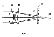
- the transition zone and/or landing zone are laser textured employing a multiple lens focusing system as illustrated in Fig. 2, which system comprises a first lens 20, such as a companion doublet, and a second lens 21, such as an aplanatic meniscus lens.
- Second lens 21 is spaced apart and positioned between the first lens 20 and rotating substrate 24 the surface of which is undergoing laser texturing.
- First lens 20 has a focal point at the upper surface of substrate 24, as at 23.
- the depth of focus of the multiple lens focusing system is extended by virtue of second lens 21 to point 25.
- the increased depth of focus provides the desired flexibility, enabling the formation of protrusions having a smaller height and diameter with greater precision and uniformity vis-à-vis a conventional single lens focusing system.
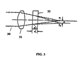
- the transition zone and/or landing zone are laser textured employing a system comprising an optical crystalline material as shown in Fig. 3, wherein pulsed laser light beam 30 is focused through lens 31.
- An optical crystalline material 32 which can comprise any of various optical crystalline materials, such as calcite or quartz, is interposed in the path of the pulsed, focused laser light beam.
- Optical crystalline material 32 is selected to have a thickness d and a crystal-induced optical access angle ⁇ , thereby creating two focus point p1 and p2 having different energy intensities.
- the focusing points p1 and p2 are separated by a distance t which is the function of the crystal thickness d and a crystal-induced optical access angle a.
- the transition zone and/or landing zone are laser textured employing both the multiple lens focusing system and an optical crystalline material positioned so that the focused pulsed laser light beam passes through the optical crystalline material before impinging on the surface undergoing laser texturing.
- the laser texturing technique of the present invention can be employed to texture a magnetic recording medium by impinging a focused laser beam not only on a rotating substrate, as in the embodiments previously disclosed, but on any layer of the magnetic recording medium.
- an underlayer such as a Cr or Cr-alloy underlayer, or magnetic layer, such as a Co-alloy magnetic layer applied on an underlayer or applied directly on a substrate, can be laser textured to form a transition zone and/or a landing zone, as with a pulsed laser light beam through a multiple lens focusing system and/or a pulsed laser light beam through an optical crystalline material.
- the laser textured pattern comprising three zones in accordance with the present invention can be provided directly on an Al or Al-alloy substrate on such a substrate after a conventional Ni-P plating has been applied.
- the laser textured surface provided in accordance with the present invention is substantially replicated in subsequently deposited layers.
- the magnetic recording media produced in accordance with the present invention can comprise any of various conventional substrates employed in the production of magnetic recording media.
- Such conventional substrates include Al, Al-alloys, such as Al-Mg alloys, NiP plated Al or NiP plated Al-alloys.
- alternative substrates such as glass and glass-ceramic material can be employed in the practice of the present invention to form a textured surface comprising a landing zone, recording zone and transition zone.
- a substrate comprising a glass or glass-ceramic material is laser textured to form a transition zone.
- Landing zone and data zone employing a pulsed laser light beam texturing system.
- a laser texturing system for use with a glass or glass-ceramic substrate in accordance with the present invention is schematically depicted in Fig. 4, and comprises CO 2 laser source 40, controlled by controller 41 and powered by generator 48.
- Emitted laser light beam 42 passes through shutter 43 to an optical system 44 comprising mirrors 44a and 44b, such as silicon mirrors, and focusing lens 45 for focusing the pulsed laser light beam onto the surface of the glass or glass-ceramic substrate 46 rotated by spindle 47. It has been found advantageous to provide lens 45 with a suitable coating, such as lead selenide.
- FIG. 5 Another laser texturing system for use with a glass or glass-ceramic substrate is schematically depicted in Fig. 5, wherein a laser light beam 51 generated by a CO 2 laser source 52 passes to beam delivery system 53 comprising mirrors 53a and 53b. Laser light beam 51 then passes through modulator 54, beam expander 55, comprising a concave lens 55a and a doublet achromatic lens 55b, and then through polarization rotator 56 to beam splitter 57 where it is separated into components 51a and 51b. Laser light beam component 51a passes to diffractive focusing lens 58 and is focused on a first surface of glass or glass-ceramic substrate 59 rotated by spindle 510.
- a laser light beam 51 generated by a CO 2 laser source 52 passes to beam delivery system 53 comprising mirrors 53a and 53b.
- Laser light beam 51 then passes through modulator 54, beam expander 55, comprising a concave lens 55a and a doublet achromatic lens 55b, and then through
- Laser light component 51b is reflected off mirrors 511a, 511b and 511c, such as silicon mirrors, to second diffractive focusing lens 512 and onto the opposite second surface of substrate 59.
- the diffractive focusing lenses 58 and 512 are advantageously coated with zinc selenide.
- a laser textured surface formed in accordance with the present invention is schematically illustrated in Fig. 6 and comprises a layer 60 of a magnetic recording medium.
- a layer can be the substrate, underlayer formed on the substrate or a magnetic layer.
- the textured surface of the present invention comprises three zones, i.e., a landing zone, transition zone and data zone.
- the landing zone comprises a plurality of protrusions 61 extending to a substantially uniform height above the textured surface.
- Data zone 63 is illustrated as polished; however, data zone 63 can also be laser textured, in which case the data zone comprises a plurality of protrusions extending to a relatively uniform height above the substrate surface but significantly lower than the height of the protrusions in the landing zone, or a pattern of grooves formed in the surface.
- the transition zone comprises a laser textured region having protrusion 62 with heights and diameters gradually decreasing and progressing from the landing zone to the data zone, thereby eliminating abrupt: topographical changes and their attendant problems.
- the magnetic layers deposited in accordance with the present invention can be any of those conventionally employed in the production of magnetic recording media.
- Such conventional magnetic alloys include, but are not limited to, cobalt (Co)-base alloys, such as cobalt-chromium (CoCr), cobalt-samarium (CoSm), cobalt-chromium-tantalum (CoCrTa), cobalt-nickel-chromium (CoNiCr), cobalt-chromium-samarium (CoCrSm), cobalt-chromium-platinum-tantalum (CoCrPtTa), cobalt-chromium-platinum (CoCrPt), cobalt-nickel-platinum (CoNiPt), cobalt-nickel-chromium-platinum (CoNiCrPt) and cobalt-chromium-platinum-boron (CoCrPtB).
- CoCr cobalt-chromium
- the thickness of the magnetic layer is consistent with conventional practices and manufacturing a magnetic recording medium.
- an underlayer can be deposited on the textured substrate prior to depositing the magnetic layer.
- the underlayer can comprise Cr or a Cr-alloy, such as chromium-vanadium or chromium-titanium, oxygen-doped Cr, tungsten or a tungsten alloy.
- a protective overcoat such as a carbon overcoat
- a lubricant topcoat deposited on the protective overcoat.
- the underlayer, magnetic layers and protective overcoat can .be applied in a conventional manner, by any of various sputtering techniques employed in production of magnetic recording media.
- a magnetic recording medium is provided with a textured surface comprising a data zone, textured landing zone comprising a plurality of protrusions extending to a substantially uniform height above the surface, and a textured transition zone, wherein the transition zone comprises a plurality of protrusions having gradually reduced heights and diameters in progressing from the landing zone to the data zone.
- the data zone can be polished or textured as by a mechanical texturing techniques.
- the landing zone can- also be textured by mechanical texturing or laser texturing.
- the transition zone is laser textured employing a pulsed laser light beam, wherein the peak pulse power and/or rotating speed of the substrate is varied to provide a plurality of protrusions having spirally reduced heights and diameters in progressing from the landing zone to the data zone.
- the landing zone has a peak surface roughness (Rp) of about 15 to about 20 nm
- the data zone has a peak surface roughness (Rp) of about 2 to about 3 nm.
Landscapes
- Chemical & Material Sciences (AREA)
- Engineering & Computer Science (AREA)
- Inorganic Chemistry (AREA)
- Metallurgy (AREA)
- Ceramic Engineering (AREA)
- Manufacturing & Machinery (AREA)
- Magnetic Record Carriers (AREA)
- Manufacturing Of Magnetic Record Carriers (AREA)
Claims (10)
- Magnetisches Aufzeichnungsmedium (60) mit einer strukturierten Oberfläche, die umfasst:dadurch gekennzeichnet, dass sich die Vorsprünge zu einer im wesentlichen gleichmäßigen Höhe über der Oberfläche erstrecken, und dadurch, dass das magnetische Aufzeichnungsmedium eine laserstrukturierte Übergangszone zwischen der Landezone und der Datenzone aufweist, wobei die Übergangszone eine Mehrzahl von Vorsprüngen umfasst, die allmählich spiralförmig verringerte Höhen und Durchmesser beim Fortschreiten von der Landezone zu der Datenzone aufweisen.eine Datenzone (63),eine strukturierte Landezone (61) mit einer. Mehrzahl von Vorsprüngen,
- Magnetisches Aufzeichnungsmedium gemäß Anspruch 1, bei dem die Landezone eine Spitzenoberflächenrauhigkeit (Rp) von etwa 15 bis 20 nm und die Datenzone eine Spitzenoberflächenrauhigkeit (Rp) von etwa 2 bis etwa 3 nm aufweist.
- Magnetisches Aufzeichnungsmedium gemäß Anspruch 1, das ein nicht-magnetisches Substrat und darauf sequentiell ausgebildet eine Magnetschicht, einen schützenden Überzug und eine Gleitdeckschicht umfasst; wobei die strukturierte Oberfläche auf dem Substrat vorgesehen ist und im wesentlichen auf den nachfolgend aufgebrachten Schichten repliziert wird.
- Verfahren zur Herstellung eines magnetischen Aufzeichnungsmediums (60), wobei das Verfahren umfasst:dadurch gekennzeichnet, dass sich die Vorsprünge zu einer im wesentlichen gleichmäßigen Höhe über der Oberfläche erstrecken; und dadurch, dass eine laserstrukturierte Übergangszone (62) zwischen der Landezone und der Datenzone ausgebildet ist, wobei die Übergangszone eine Mehrzahl von Vorsprüngen umfasst, die allmählich verringerte Höhen und Durchmesser beim Fortschreiten von der Landezone zu der Datenzone aufweisen.Bilden einer strukturierten Oberfläche auf einer Schicht des magnetischen Aufzeichnungsmediums, wobei die strukturierte Oberfläche umfasst:eine Datenzone (63),eine strukturierte Landezone (61), die eine Mehrzahl von Vorsprüngen umfasst,
- Verfahren gemäß Anspruch 4 mit:Bilden der Datenzone,Bilden der Landezone,Bilden der Übergangszone durch Belichten der Oberfläche zwischen der Landezone und der Datenzone mit einem gepulsten Laserlichtstrahl, um die Vorsprünge zu bilden, während sich die Oberfläche dreht, wobei die Übergangszone eine Mehrzahl von Vorsprüngen mit spiralförmig verringerten Höhen und Durchmessern umfasst.
- Verfahren gemäß Anspruch 5 mit einem Verändern der Spitzenleistung des gepulsten Laserlichtstrahls und/oder Verändern der Drehgeschwindigkeit der Oberfläche.
- Verfahren gemäß Anspruch 6 mit einem Verändern der Spitzenleistung des gepulsten Laserlichtstrahls und/oder Erhöhen der Geschwindigkeit der sich drehenden Oberfläche beim Bilden der Übergangszone beim Fortschreiten von der Landezone zu der Datenzone.
- Verfahren gemäß Anspruch 4 mit:Bilden der strukturierten Oberfläche auf einem nichtmagnetischen Substrat, undsequentiell darauf Bilden einer Magnetschicht, eines schützenden Überzugs und einer Gleitdeckschicht, wobei die strukturierte Oberfläche im wesentlichen auf den nachfolgend aufgebrachten Schichten repliziert wird.
- Verfahren gemäß Anspruch 4, mit einem Strukturieren der Landezone und/oder der Übergangszone durch Belichten einer Oberfläche des Substrats mit einem gepulsten fokussierten Laserlichtstrahl mit einer Wellenlänge von etwa 10 µm.
- Verfahren gemäß Anspruch 5, mit einem Strukturieren der Landezone und/oder der Übergangszone durch Belichten der Oberfläche mit einem gepulsten Laserlichtstrahl durch ein Mehrfachlinsen-Fokussierungssystem, das eine erste Linse und eine zweite Linse enthält, die beabstandet und zwischen der ersten Linse der oberen Oberfläche des Substrats positioniert ist.
Applications Claiming Priority (1)
| Application Number | Priority Date | Filing Date | Title |
|---|---|---|---|
| PCT/US1996/009330 WO1997047001A1 (en) | 1996-06-05 | 1996-06-05 | Textured magnetic recording medium having a transition zone |
Publications (2)
| Publication Number | Publication Date |
|---|---|
| EP0902944A1 EP0902944A1 (de) | 1999-03-24 |
| EP0902944B1 true EP0902944B1 (de) | 2003-05-28 |
Family
ID=22255255
Family Applications (1)
| Application Number | Title | Priority Date | Filing Date |
|---|---|---|---|
| EP96918269A Expired - Lifetime EP0902944B1 (de) | 1996-06-05 | 1996-06-05 | Texturiertes magnetisches aufzeichnungsmedium mit übergangszone |
Country Status (4)
| Country | Link |
|---|---|
| EP (1) | EP0902944B1 (de) |
| JP (1) | JP2002513493A (de) |
| DE (1) | DE69628463T2 (de) |
| WO (1) | WO1997047001A1 (de) |
Families Citing this family (1)
| Publication number | Priority date | Publication date | Assignee | Title |
|---|---|---|---|---|
| DE102004010336A1 (de) | 2003-03-05 | 2004-09-16 | Komag, Inc., San Jose | Magnetische Aufzeichnungsplatte mit Übergangszone |
Family Cites Families (11)
| Publication number | Priority date | Publication date | Assignee | Title |
|---|---|---|---|---|
| US4060306A (en) | 1974-12-16 | 1977-11-29 | American Optical Corporation | Achromatic aplanatic condenser |
| US4307408A (en) | 1976-04-28 | 1981-12-22 | Canon Kabushiki Kaisha | Recording apparatus using coherent light |
| US5120927A (en) | 1988-06-03 | 1992-06-09 | Insite Peripherals, Inc. | High track density media with optical servo tracks and method and apparatus for inscribing the tracks on the media |
| US5167096A (en) | 1990-02-26 | 1992-12-01 | Hmt Technology Corporation | Method for texturing a magnetic disc substrate |
| JPH06318381A (ja) * | 1992-08-19 | 1994-11-15 | Komag Inc | ハードディスクドライブ装置、磁気ディスク及びリードライトヘッド |
| TW300879B (de) | 1993-11-10 | 1997-03-21 | Ibm | |
| DE19524220A1 (de) * | 1994-07-04 | 1996-01-11 | Mitsubishi Chem Corp | Magnetisches Aufzeichnungsmedium, Verfahren zu dessen Herstellung, und Aufnahme- und Wiedergabeverfahren |
| US5586040A (en) | 1995-01-27 | 1996-12-17 | International Business Machines Corporation | Process and apparatus for controlled laser texturing of magnetic recording disk |
| US5582878A (en) | 1995-03-24 | 1996-12-10 | Showa Denko Kabushiki Kaisha | Process for producing magnetic recording medium |
| US5520981A (en) * | 1995-04-24 | 1996-05-28 | Hmt Technology Corporation | Magnetic recording disk with overcoat thickness gradient between a data zone and a landing zone |
| US5506017A (en) | 1995-06-07 | 1996-04-09 | Komag Incorporated | Method for texturing magnetic media |
-
1996
- 1996-06-05 JP JP50052098A patent/JP2002513493A/ja active Pending
- 1996-06-05 DE DE69628463T patent/DE69628463T2/de not_active Expired - Fee Related
- 1996-06-05 EP EP96918269A patent/EP0902944B1/de not_active Expired - Lifetime
- 1996-06-05 WO PCT/US1996/009330 patent/WO1997047001A1/en not_active Ceased
Also Published As
| Publication number | Publication date |
|---|---|
| JP2002513493A (ja) | 2002-05-08 |
| WO1997047001A1 (en) | 1997-12-11 |
| HK1018532A1 (en) | 1999-12-24 |
| DE69628463T2 (de) | 2004-04-01 |
| EP0902944A1 (de) | 1999-03-24 |
| DE69628463D1 (de) | 2003-07-03 |
Similar Documents
| Publication | Publication Date | Title |
|---|---|---|
| US5714207A (en) | Method of laser texturing glass or glass-ceramic substrates for magnetic recording media | |
| US6020045A (en) | Textured magnetic recording medium having a transition zone | |
| US5861196A (en) | Laser texturing a glass or glass-ceramic substrate | |
| US5958545A (en) | Controlled laser texturing glass-ceramic substrates for magnetic recording media | |
| US5783797A (en) | Laser texturing of magnetic recording medium using a crystal material | |
| US6297910B1 (en) | Laser-texturing data zone on a magnetic disk surface by using degenerative two wave mixing | |
| US5718811A (en) | Sputter textured magnetic recording medium | |
| US5952058A (en) | Laser texturing magnetic recording medium using fiber optics | |
| US5955154A (en) | Magnetic recording medium with laser textured glass or glass-ceramic substrate | |
| US5837330A (en) | Dual fiber optic laser texturing | |
| EP0902944B1 (de) | Texturiertes magnetisches aufzeichnungsmedium mit übergangszone | |
| EP0897576B1 (de) | Laserstrukturierung eines magnetischen aufzeichnungsmediums unter verwendung einer mehrfachlinsenfokussierung | |
| US6207926B1 (en) | Fiber optic laser texturing with optical probe feedback control | |
| US5945197A (en) | Laser texturing of magnetic recording medium using multiple lens focusing | |
| US6205002B1 (en) | Disk drive with textured slider contact region | |
| US6093472A (en) | Magnetic recording medium with laser textured glass or glass-ceramic substrate | |
| HK1018532B (en) | Textured magnetic recording medium having a transition zone | |
| US6068728A (en) | Laser texturing with reverse lens focusing system | |
| KR100415421B1 (ko) | 전이영역을가진텍스츄어링된자기기록매체 | |
| EP0962916A1 (de) | Laserstrukturierung eines magnetischen Aufzeichnungsmediums unter Verwendung einer Mehrfachlinsenfokussierung | |
| US6180916B1 (en) | Method of manufacturing a magnetic recording medium with a laser textured data zone | |
| KR100378496B1 (ko) | 다수렌즈포커싱시스템을이용한텍스춰링된표면을갖는자기기록매체및그제조방법 | |
| KR100629034B1 (ko) | 패턴화된 기판을 가진 자기 기록 매체 | |
| HK1018531B (en) | Laser texturing of magnetic recording medium using multiple lens focusing | |
| US6320728B1 (en) | Laser textured magnetic surface micro-ridges/grooves to enhance magnetic recording performance |
Legal Events
| Date | Code | Title | Description |
|---|---|---|---|
| PUAI | Public reference made under article 153(3) epc to a published international application that has entered the european phase |
Free format text: ORIGINAL CODE: 0009012 |
|
| 17P | Request for examination filed |
Effective date: 19981221 |
|
| AK | Designated contracting states |
Kind code of ref document: A1 Designated state(s): DE GB |
|
| RAP1 | Party data changed (applicant data changed or rights of an application transferred) |
Owner name: SEAGATE TECHNOLOGY LLC |
|
| 17Q | First examination report despatched |
Effective date: 20011018 |
|
| GRAH | Despatch of communication of intention to grant a patent |
Free format text: ORIGINAL CODE: EPIDOS IGRA |
|
| GRAH | Despatch of communication of intention to grant a patent |
Free format text: ORIGINAL CODE: EPIDOS IGRA |
|
| GRAH | Despatch of communication of intention to grant a patent |
Free format text: ORIGINAL CODE: EPIDOS IGRA |
|
| GRAA | (expected) grant |
Free format text: ORIGINAL CODE: 0009210 |
|
| AK | Designated contracting states |
Designated state(s): DE GB |
|
| REG | Reference to a national code |
Ref country code: GB Ref legal event code: FG4D |
|
| PGFP | Annual fee paid to national office [announced via postgrant information from national office to epo] |
Ref country code: DE Payment date: 20030627 Year of fee payment: 8 |
|
| REF | Corresponds to: |
Ref document number: 69628463 Country of ref document: DE Date of ref document: 20030703 Kind code of ref document: P |
|
| PLBE | No opposition filed within time limit |
Free format text: ORIGINAL CODE: 0009261 |
|
| STAA | Information on the status of an ep patent application or granted ep patent |
Free format text: STATUS: NO OPPOSITION FILED WITHIN TIME LIMIT |
|
| 26N | No opposition filed |
Effective date: 20040302 |
|
| PGFP | Annual fee paid to national office [announced via postgrant information from national office to epo] |
Ref country code: GB Payment date: 20040601 Year of fee payment: 9 |
|
| PG25 | Lapsed in a contracting state [announced via postgrant information from national office to epo] |
Ref country code: DE Free format text: LAPSE BECAUSE OF NON-PAYMENT OF DUE FEES Effective date: 20050101 |
|
| PG25 | Lapsed in a contracting state [announced via postgrant information from national office to epo] |
Ref country code: GB Free format text: LAPSE BECAUSE OF NON-PAYMENT OF DUE FEES Effective date: 20050605 |
|
| GBPC | Gb: european patent ceased through non-payment of renewal fee |
Effective date: 20050605 |