EP0902939B1 - Holder for swivelling panels or the like - Google Patents
Holder for swivelling panels or the like Download PDFInfo
- Publication number
- EP0902939B1 EP0902939B1 EP97926991A EP97926991A EP0902939B1 EP 0902939 B1 EP0902939 B1 EP 0902939B1 EP 97926991 A EP97926991 A EP 97926991A EP 97926991 A EP97926991 A EP 97926991A EP 0902939 B1 EP0902939 B1 EP 0902939B1
- Authority
- EP
- European Patent Office
- Prior art keywords
- holder
- pins
- basic body
- wall
- flip
- Prior art date
- Legal status (The legal status is an assumption and is not a legal conclusion. Google has not performed a legal analysis and makes no representation as to the accuracy of the status listed.)
- Expired - Lifetime
Links
Images
Classifications
-
- G—PHYSICS
- G09—EDUCATION; CRYPTOGRAPHY; DISPLAY; ADVERTISING; SEALS
- G09F—DISPLAYING; ADVERTISING; SIGNS; LABELS OR NAME-PLATES; SEALS
- G09F7/00—Signs, name or number plates, letters, numerals, or symbols; Panels or boards
- G09F7/18—Means for attaching signs, plates, panels, or boards to a supporting structure
Definitions
- the invention relates to a holder, in particular wall holder for reversible boards and reversible bags or covers, those in the area of the top and bottom of one of their Edges with swivel bearings for the top and bottom Provide the edge of the holder arranged in rows are.
- Holders of the above type are particularly large in scope in offices, laboratories, workshops and supermarkets used. They are easy to handle and enable the user has quick access to indexes, Parts lists, standard sheets, price lists and the like Documentation contained information.
- Holders of the type described consist of a metallic body and with this by riveting connected injection molded parts made of plastic, the injection molded parts each with a series of Pins are provided.
- the reasons for the multi-part Structure of the known holder can be found in that one was trying, on the one hand, the stability of the holder to ensure by its metallic base and on the other hand the cost of manufacturing the rows of tenons to keep within reasonable limits.
- the invention has for its object a holder of the kind under consideration to create its basic body together with the rows of tenons in one operation is producible and both in terms of its Stability as well as its manufacturing costs high demands enough.
- This object is achieved according to the invention solved that the holder one as an injection molded part trained bowl-shaped base body with a Has rear wall that in the area of the pin Windows are provided, the height of which is greater than the length and their width is larger than the diameter of the pin is, with an edge of each window with the Inside one of the cones one row of cones supporting front wall of the base body is aligned.
- the holder according to the invention has the advantage that it using a simple injection mold, i.e. an injection molding tool, in which on slide can be dispensed with, can be produced in one operation is.
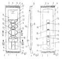
- the basic body of a holder is 1 for known and therefore not shown Swivel panels referred to, the opposite Ends one of their edges with swivel bearings for at the top and lower edge of the holder arranged rows of pins 2 are provided.
- the drawn holder has ten Pairs of pins on and is therefore suitable for the bracket out of ten, for example, trained as scale boards Swivel boards.
- To inexpensive manufacture of the as Plastic molded part to enable trained holder is the rear wall 3 in the region of the pin 2 provided with windows 4, the use of slide-less Allow injection molds.
- the rear wall of the holder consists of two wall sections 10 and 11 that are in the lower third of the holder Merge into one another at an obtuse angle.
- Longitudinal struts 12 and cross struts 13 in the region of the trough 9 contribute significantly to the stability of the holder.
- Four arranged in the center of the trough 9 perpendicular to the longitudinal axis of the holder cross struts 13 are with aligned through openings 14 provided that Allow insertion of a support column into the trough 9.
- In the wall section 11 is a guide channel 16 for a support column embedded.
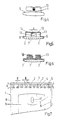
- the height H of the window 4th greater than length 1 and width B of window 4 larger than the diameter d of the pin 2.
- the width W of the window 15 is equal to the width b Cutouts 14.
- the wall section 10 with from Openings 17 and 18 formed elongated holes, whose longitudinal axes are perpendicular to each other adjust the position of the holder within certain limits can.
Abstract
Description
Die Erfindung betrifft einen Halter, insbesondere Wandhalter für Wendetafeln und Wendetaschen bzw. -hüllen, die im Bereich des oberen und unteren Endes eines ihrer Ränder mit Schwenklagern für jeweils am oberen und unteren Rand des Halters in Reihe angeordnete Zapfen versehen sind.The invention relates to a holder, in particular wall holder for reversible boards and reversible bags or covers, those in the area of the top and bottom of one of their Edges with swivel bearings for the top and bottom Provide the edge of the holder arranged in rows are.
Halter der vorstehenden Art werden in großem Umfang insbesondere in Büros, Labors, Werkstätten und Supermärkten eingesetzt. Sie sind leicht handhabbar und ermöglichen dem Anwender einen schnellen Zugriff zu in Sachverzeichnissen, Stücklisten, Normblättern, Preislisten und ähnlichen Unterlagen enthaltenen Informationen.Holders of the above type are particularly large in scope in offices, laboratories, workshops and supermarkets used. They are easy to handle and enable the user has quick access to indexes, Parts lists, standard sheets, price lists and the like Documentation contained information.
Bekannt sind Halter der beschriebenen Art, die aus einem metallischen Grundkörper und mit diesem durch Nieten verbundenen Spritzgußteilen aus Kunststoff bestehen, wobei die Spritzgußteile mit jeweils einer Reihe von Zapfen versehen sind. Die Gründe für den mehrteiligen Aufbau der bekannten Halter sind darin zu suchen, daß man bemüht war, einerseits die Stabilität des Halters durch dessen metallischen Grundkörper zu gewährleisten und andererseits die Kosten für die Fertigung der Zapfenreihen in vertretbaren Grenzen zu halten.Holders of the type described are known, which consist of a metallic body and with this by riveting connected injection molded parts made of plastic, the injection molded parts each with a series of Pins are provided. The reasons for the multi-part Structure of the known holder can be found in that one was trying, on the one hand, the stability of the holder to ensure by its metallic base and on the other hand the cost of manufacturing the rows of tenons to keep within reasonable limits.
Der Erfindung liegt die Aufgabe zugrunde, einen Halter der in Betracht gezogenen Art zu schaffen, dessen Grundkörper zusammen mit den Zapfenreihen in einem Arbeitsgang herstellbar ist und der sowohl hinsichtlich seiner Stabilität als auch seiner Herstellungskosten hohen Ansprüchen genügt. Diese Aufgabe wird erfindungsgemäß dadurch gelöst, daß der Halter einen als Spritzgußteil ausgebildeten schalenförmigen Grundkörper mit einer Rückwand aufweist, die im Bereich der Zapfen mit Fenstern versehen ist, deren Höhe größer als die Länge und deren Breite größer als der Durchmesser der Zapfen ist, wobei jeweils ein Rand eines jeden Fensters mit der Innenseite einer die Zapfen jeweils einer Zapfenreihe tragenden Stirnwand des Grundkörpers fluchtet.The invention has for its object a holder of the kind under consideration to create its basic body together with the rows of tenons in one operation is producible and both in terms of its Stability as well as its manufacturing costs high demands enough. This object is achieved according to the invention solved that the holder one as an injection molded part trained bowl-shaped base body with a Has rear wall that in the area of the pin Windows are provided, the height of which is greater than the length and their width is larger than the diameter of the pin is, with an edge of each window with the Inside one of the cones one row of cones supporting front wall of the base body is aligned.
Der erfindungsgemäße Halter bietet den Vorteil, daß er unter Verwendung eines einfachen Spritzgußwerkzeuges, d.h. eines Spritzgußwerkzeuges, bei dem auf Schieber verzichtet werden kann, in einem Arbeitsgang herstellbar ist.The holder according to the invention has the advantage that it using a simple injection mold, i.e. an injection molding tool, in which on slide can be dispensed with, can be produced in one operation is.
Weitere Einzelheiten und Merkmale der Erfindung ergeben
sich aus den Unteransprüchen und der nachstehenden Beschreibung
einer in der beigefügten Zeichnung dargestellten
besonders vorteilhaften Ausführungsform. Es
zeigen:
In den Figuren ist mit 1 der Grundkörper eines Halters
für bekannte und deshalb nicht dargestellte
Schwenktafeln bezeichnet, die an sich gegenüberliegenden
Enden eines ihrer Ränder mit Schwenklagern für am oberen
und unteren Rand des Halters angeordnete Reihen von Zapfen
2 versehen sind. Der gezeichnete Halter weist zehn
Zapfenpaare auf und eignet sich mithin für die Halterung
von zehn beispielsweise als Schuppentafeln ausgebildeten
Schwenktafeln. Um eine kostengünstige Fertigung des als
Kunststoffspritzgußteil ausgebildeten Halters zu ermöglichen,
ist dessen Rückwand 3 im Bereich der Zapfen 2
mit Fenstern 4 versehen, die den Einsatz von schieberlosen
Spritzwerkzeugen ermöglichen. Um dem Halter eine
hinreichende Stabilität zu vermitteln, ist er schalenförmig
ausgebildet. Er weist von einem durchgehenden
Steg gebildete Stirn- und Seitenwände 5, 6, 7 und 8 sowie
eine zentrale Mulde 9 auf. Im Bereich der Mulde 9
besteht die Rückwand des Halters aus zwei Wandabschnitten
10 und 11, die im unteren Drittel des Halters unter
Bildung eines stumpfen Winkels ineinander übergehen.
Längsstreben 12 und Querstreben 13 im Bereich der Mulde
9 tragen maßgeblich zur Stabilität des Halters bei. Vier
im Zentrum der Mulde 9 angeordnete senkrecht zur Längsachse
des Halters verlaufende Querstreben 13 sind mit
fluchtenden Durchstecköffnungen 14 versehen, die das
Einschieben einer Haltesäule in die Mulde 9 ermöglichen.
Um auch diese Aussparungen kostengünstig fertigen zu
können, befinden sich im Wandabschnitt 10 Fenster 15.
In den Wandabschnitt 11 ist ein Führungskanal 16 für
eine Haltesäule eingelassen. Wie den Figuren 1, 5 und 7
entnommen werden kann, ist die Höhe H der Fenster 4
größer als die Länge 1 und die Breite B der Fenster 4
größer als der Durchmesser d der Zapfen 2. Demgegenüber
ist die Weite W der Fenster 15 gleich der Breite b der
Aussparungen 14. In the figures, the basic body of a holder is 1
for known and therefore not shown
Swivel panels referred to, the opposite
Ends one of their edges with swivel bearings for at the top
and lower edge of the holder arranged rows of
Um den Halter mit Hilfe von Schrauben an einer Wand befestigen
zu können, ist der Wandabschnitt 10 mit von
Langlöchern gebildeten Durchbrüchen 17 und 18 ausgestattet,
deren Längsachsen senkrecht zueinander stehen, um
die Lage des Halters in gewissen Grenzen justieren zu
können.To attach the holder to a wall using screws
to be able to, the
Claims (4)
- Holder, in particular wall holder, for flip boards and/or flip pockets and flip sheaths which are provided in the region of the upper and lower end of one of their edges with swivel bearings for pins arranged in each case in a row at the upper and lower edge of the holder, characterized in that the holder has a shell-shaped basic body (1) constructed as an injection-moulded part and with a rear wall (3) which is provided in the region of the pins (2) with windows (4) whose height (H) is greater than the length (1) and whose breadth (B) is greater than the diameter (d) of the pins (2), one edge of each window (4) being aligned in each case with the inside of an end wall (5, 7) of the basic body (1) bearing the pins (2) of in each case one row of pins.
- Holder according to Claim 1, characterized in that its basic body (1) is provided with circumferential end and side walls (5, 6, 7, 8) as well as a central trough (9).
- Holder according to Claim 2, characterized in that the basic body (1) is fitted in the region of its central trough (9) with longitudinal and transverse struts (12, 13) serving the purpose of reinforcement.
- Holder according to Claim 3, characterized in that a portion of the transverse struts (13) constructed as a web is provided with cutouts (14) to which additional windows (15) in the rear wall (3) of the basic body (1) are assigned whose width (W) is equal to the breadth (b) of the cutouts (14).
Applications Claiming Priority (3)
| Application Number | Priority Date | Filing Date | Title |
|---|---|---|---|
| DE19623904 | 1996-06-07 | ||
| DE19623904A DE19623904C2 (en) | 1996-06-07 | 1996-06-07 | Holder for turning boards or the like |
| PCT/DE1997/001156 WO1997048088A1 (en) | 1996-06-07 | 1997-06-02 | Holder for swivelling panels or the like |
Publications (2)
| Publication Number | Publication Date |
|---|---|
| EP0902939A1 EP0902939A1 (en) | 1999-03-24 |
| EP0902939B1 true EP0902939B1 (en) | 2000-03-15 |
Family
ID=7797028
Family Applications (1)
| Application Number | Title | Priority Date | Filing Date |
|---|---|---|---|
| EP97926991A Expired - Lifetime EP0902939B1 (en) | 1996-06-07 | 1997-06-02 | Holder for swivelling panels or the like |
Country Status (13)
| Country | Link |
|---|---|
| US (1) | US6250598B1 (en) |
| EP (1) | EP0902939B1 (en) |
| JP (1) | JP4091662B2 (en) |
| AT (1) | ATE190748T1 (en) |
| AU (1) | AU719687B2 (en) |
| CA (1) | CA2257195C (en) |
| DE (2) | DE19623904C2 (en) |
| DK (1) | DK0902939T3 (en) |
| ES (1) | ES2145607T3 (en) |
| NO (1) | NO312986B1 (en) |
| PL (1) | PL182195B1 (en) |
| RU (1) | RU2175786C2 (en) |
| WO (1) | WO1997048088A1 (en) |
Families Citing this family (3)
| Publication number | Priority date | Publication date | Assignee | Title |
|---|---|---|---|---|
| DE19703754C2 (en) * | 1997-01-24 | 1999-07-08 | Hunke & Jochheim | Stand |
| DE19955376A1 (en) * | 1999-11-10 | 2001-06-07 | Hunke & Jochheim | Holder for turning boards or the like |
| DE102006002550B4 (en) * | 2006-01-18 | 2021-02-25 | "Durable" Hunke & Jochheim Gmbh & Co. Kommanditgesellschaft | Stand with a holder for reversible boards, reversible bags or reversible covers |
Family Cites Families (15)
| Publication number | Priority date | Publication date | Assignee | Title |
|---|---|---|---|---|
| DE178811C (en) * | ||||
| US1866089A (en) * | 1925-07-27 | 1932-07-05 | Remington Rand Inc | Index or file |
| CH168403A (en) * | 1933-04-07 | 1934-04-15 | Weydknecht Louis | Blackboard aggregate. |
| US2138848A (en) * | 1937-09-22 | 1938-12-06 | Sears Roebuck & Co | Upright loose-leaf catalogue or file |
| US2617219A (en) * | 1949-10-15 | 1952-11-11 | Globe Wernicke Co | Visible reference desk stand |
| US3092256A (en) * | 1960-12-01 | 1963-06-04 | Vernik David | Phonograph record rack |
| US3412496A (en) * | 1965-12-10 | 1968-11-26 | Canteen Corp | Remote control selector for automatic phonographs |
| US3514883A (en) * | 1968-08-12 | 1970-06-02 | Alto O Albright | Pivotal display panel installation |
| US4456286A (en) * | 1981-01-06 | 1984-06-26 | Walker Jamar | Apparatus for wall mounted presentation boards |
| US4403761A (en) * | 1981-01-06 | 1983-09-13 | Walker Jamar | Apparatus for wall mounted presentation boards |
| US4684099A (en) * | 1986-10-06 | 1987-08-04 | Krapf Wallace A | Pivotally mounted scheduling boards |
| US4831758A (en) * | 1986-10-31 | 1989-05-23 | Seeburg Phonograph Corporation | Jukebox display unit |
| US5031346A (en) * | 1989-07-24 | 1991-07-16 | Rowe International, Inc. | Jukebox selection display and page turning mechanism therefor |
| US5077923A (en) * | 1989-09-07 | 1992-01-07 | Rock-Ola Manufacturing Corporation | Program display for coin operated compact disc phonograph |
| US5222611A (en) * | 1992-03-26 | 1993-06-29 | Wood Robert G | Wall-unit hanging system |
-
1996
- 1996-06-07 DE DE19623904A patent/DE19623904C2/en not_active Expired - Fee Related
-
1997
- 1997-06-02 AT AT97926991T patent/ATE190748T1/en active
- 1997-06-02 AU AU31648/97A patent/AU719687B2/en not_active Expired
- 1997-06-02 DE DE59701265T patent/DE59701265D1/en not_active Expired - Lifetime
- 1997-06-02 DK DK97926991T patent/DK0902939T3/en active
- 1997-06-02 EP EP97926991A patent/EP0902939B1/en not_active Expired - Lifetime
- 1997-06-02 CA CA002257195A patent/CA2257195C/en not_active Expired - Lifetime
- 1997-06-02 US US09/194,813 patent/US6250598B1/en not_active Expired - Lifetime
- 1997-06-02 ES ES97926991T patent/ES2145607T3/en not_active Expired - Lifetime
- 1997-06-02 WO PCT/DE1997/001156 patent/WO1997048088A1/en active IP Right Grant
- 1997-06-02 PL PL97330319A patent/PL182195B1/en unknown
- 1997-06-02 JP JP50105898A patent/JP4091662B2/en not_active Expired - Lifetime
- 1997-06-02 RU RU99100295/09A patent/RU2175786C2/en active
-
1998
- 1998-12-04 NO NO19985678A patent/NO312986B1/en not_active IP Right Cessation
Also Published As
| Publication number | Publication date |
|---|---|
| EP0902939A1 (en) | 1999-03-24 |
| JP4091662B2 (en) | 2008-05-28 |
| AU3164897A (en) | 1998-01-07 |
| DE19623904A1 (en) | 1997-12-11 |
| RU2175786C2 (en) | 2001-11-10 |
| PL182195B1 (en) | 2001-11-30 |
| CA2257195C (en) | 2006-08-15 |
| NO985678D0 (en) | 1998-12-04 |
| CA2257195A1 (en) | 1997-12-18 |
| US6250598B1 (en) | 2001-06-26 |
| DE59701265D1 (en) | 2000-04-20 |
| WO1997048088A1 (en) | 1997-12-18 |
| ATE190748T1 (en) | 2000-04-15 |
| DK0902939T3 (en) | 2000-08-21 |
| NO312986B1 (en) | 2002-07-22 |
| ES2145607T3 (en) | 2000-07-01 |
| DE19623904C2 (en) | 1999-05-20 |
| AU719687B2 (en) | 2000-05-18 |
| PL330319A1 (en) | 1999-05-10 |
| NO985678L (en) | 1999-02-05 |
| JP2001509274A (en) | 2001-07-10 |
Similar Documents
| Publication | Publication Date | Title |
|---|---|---|
| EP0382902B1 (en) | Folding flat ballpoint writing instrument | |
| DE3707410A1 (en) | Sales shelving divider | |
| DE19703754C2 (en) | Stand | |
| EP2191074B1 (en) | Shovel apparatus for a snow shovel | |
| EP0902939B1 (en) | Holder for swivelling panels or the like | |
| EP0902938B1 (en) | Holder for swivelling panels or the like | |
| EP1791102B1 (en) | Displayholder with support legs | |
| EP3626317A1 (en) | Goal | |
| DE2848236A1 (en) | HOLDER FOR SHELVES OR DGL. | |
| DE1090948B (en) | Movable runner designed for display boards | |
| EP1227745B1 (en) | Bracket for turnable boards or similar | |
| WO1998003351A1 (en) | Information system display panel | |
| DE3118695C2 (en) | Holding device for brochures and the like. | |
| EP0819395A2 (en) | Shelf | |
| DE10101885B4 (en) | A container assembly | |
| DE102016119455B4 (en) | Furniture attachment with two swiveling base parts | |
| EP1266371A1 (en) | Device for holding turning plates or the like | |
| DE3433438C2 (en) | ||
| CH637065A5 (en) | HOLDER FOR RECEIVING A MOUNT FOR FIXED SHEETS. | |
| DE202006016628U1 (en) | Poster display unit has at least one board-shaped poster holder on which stand legs are provided and equipped with rear wall on which poster is positioned | |
| EP0212346A2 (en) | Container for documents | |
| DE7633308U1 (en) | PLANTING TROUGH, IN PARTICULAR FOR ACCOMMODATION OF POT PLANTS | |
| DE202004001827U1 (en) | Sign, has edges of cover panel and information carrier held in undercut groove by sliding clamp | |
| DE202006015765U1 (en) | Storage device for holding sorted printed products like documents, leaflets and index cards has a tray-like underpart with a rectangular base surface, side-walls and separating panels | |
| DE1964800A1 (en) | Front panel for letter boxes |
Legal Events
| Date | Code | Title | Description |
|---|---|---|---|
| PUAI | Public reference made under article 153(3) epc to a published international application that has entered the european phase |
Free format text: ORIGINAL CODE: 0009012 |
|
| 17P | Request for examination filed |
Effective date: 19981127 |
|
| AK | Designated contracting states |
Kind code of ref document: A1 Designated state(s): AT BE CH DE DK ES FI FR GB IT LI NL SE |
|
| GRAG | Despatch of communication of intention to grant |
Free format text: ORIGINAL CODE: EPIDOS AGRA |
|
| 17Q | First examination report despatched |
Effective date: 19990712 |
|
| GRAG | Despatch of communication of intention to grant |
Free format text: ORIGINAL CODE: EPIDOS AGRA |
|
| GRAH | Despatch of communication of intention to grant a patent |
Free format text: ORIGINAL CODE: EPIDOS IGRA |
|
| GRAH | Despatch of communication of intention to grant a patent |
Free format text: ORIGINAL CODE: EPIDOS IGRA |
|
| GRAA | (expected) grant |
Free format text: ORIGINAL CODE: 0009210 |
|
| AK | Designated contracting states |
Kind code of ref document: B1 Designated state(s): AT BE CH DE DK ES FI FR GB IT LI NL SE |
|
| REF | Corresponds to: |
Ref document number: 190748 Country of ref document: AT Date of ref document: 20000415 Kind code of ref document: T |
|
| REG | Reference to a national code |
Ref country code: CH Ref legal event code: EP |
|
| REF | Corresponds to: |
Ref document number: 59701265 Country of ref document: DE Date of ref document: 20000420 |
|
| REG | Reference to a national code |
Ref country code: CH Ref legal event code: NV Representative=s name: E. BLUM & CO. PATENTANWAELTE |
|
| ITF | It: translation for a ep patent filed |
Owner name: DE DOMINICIS & MAYER S.R.L. |
|
| GBT | Gb: translation of ep patent filed (gb section 77(6)(a)/1977) |
Effective date: 20000508 |
|
| ET | Fr: translation filed | ||
| REG | Reference to a national code |
Ref country code: ES Ref legal event code: FG2A Ref document number: 2145607 Country of ref document: ES Kind code of ref document: T3 |
|
| REG | Reference to a national code |
Ref country code: DK Ref legal event code: T3 |
|
| PLBE | No opposition filed within time limit |
Free format text: ORIGINAL CODE: 0009261 |
|
| STAA | Information on the status of an ep patent application or granted ep patent |
Free format text: STATUS: NO OPPOSITION FILED WITHIN TIME LIMIT |
|
| 26N | No opposition filed | ||
| REG | Reference to a national code |
Ref country code: GB Ref legal event code: IF02 |
|
| REG | Reference to a national code |
Ref country code: CH Ref legal event code: PFA Owner name: "DURABLE" HUNKE & JOCHHEIM GMBH & CO. KOMMANDITGE Free format text: "DURABLE" HUNKE & JOCHHEIM GMBH & CO. KOMMANDITGESELLSCHAFT#WESTFALENSTRASSE 77-79#D-58636 ISERLOHN (DE) -TRANSFER TO- "DURABLE" HUNKE & JOCHHEIM GMBH & CO. KOMMANDITGESELLSCHAFT#WESTFALENSTRASSE 77-79#D-58636 ISERLOHN (DE) |
|
| REG | Reference to a national code |
Ref country code: DE Ref legal event code: R082 Ref document number: 59701265 Country of ref document: DE Representative=s name: BECKORD & NIEDLICH PATENTANWALTSKANZLEI, DE |
|
| REG | Reference to a national code |
Ref country code: DE Ref legal event code: R082 Ref document number: 59701265 Country of ref document: DE Representative=s name: BECKORD & NIEDLICH PATENTANWALTSKANZLEI, DE Effective date: 20140114 Ref country code: DE Ref legal event code: R081 Ref document number: 59701265 Country of ref document: DE Owner name: "DURABLE" HUNKE & JOCHHEIM GMBH & CO. KOMMANDI, DE Free format text: FORMER OWNER: "DURABLE" HUNKE & JOCHHEIM GMBH & CO. KG, 58636 ISERLOHN, DE Effective date: 20140114 |
|
| PGFP | Annual fee paid to national office [announced via postgrant information from national office to epo] |
Ref country code: AT Payment date: 20140522 Year of fee payment: 18 Ref country code: FI Payment date: 20140522 Year of fee payment: 18 |
|
| PG25 | Lapsed in a contracting state [announced via postgrant information from national office to epo] |
Ref country code: FI Free format text: LAPSE BECAUSE OF NON-PAYMENT OF DUE FEES Effective date: 20150602 |
|
| REG | Reference to a national code |
Ref country code: AT Ref legal event code: MM01 Ref document number: 190748 Country of ref document: AT Kind code of ref document: T Effective date: 20150602 |
|
| PG25 | Lapsed in a contracting state [announced via postgrant information from national office to epo] |
Ref country code: AT Free format text: LAPSE BECAUSE OF NON-PAYMENT OF DUE FEES Effective date: 20150602 |
|
| REG | Reference to a national code |
Ref country code: FR Ref legal event code: PLFP Year of fee payment: 20 |
|
| PGFP | Annual fee paid to national office [announced via postgrant information from national office to epo] |
Ref country code: GB Payment date: 20160621 Year of fee payment: 20 Ref country code: ES Payment date: 20160614 Year of fee payment: 20 Ref country code: CH Payment date: 20160620 Year of fee payment: 20 |
|
| PGFP | Annual fee paid to national office [announced via postgrant information from national office to epo] |
Ref country code: DK Payment date: 20160620 Year of fee payment: 20 Ref country code: NL Payment date: 20160620 Year of fee payment: 20 Ref country code: BE Payment date: 20160620 Year of fee payment: 20 Ref country code: SE Payment date: 20160620 Year of fee payment: 20 Ref country code: FR Payment date: 20160627 Year of fee payment: 20 |
|
| PGFP | Annual fee paid to national office [announced via postgrant information from national office to epo] |
Ref country code: IT Payment date: 20160628 Year of fee payment: 20 Ref country code: DE Payment date: 20160630 Year of fee payment: 20 |
|
| REG | Reference to a national code |
Ref country code: DE Ref legal event code: R071 Ref document number: 59701265 Country of ref document: DE |
|
| REG | Reference to a national code |
Ref country code: DK Ref legal event code: EUP Effective date: 20170602 |
|
| REG | Reference to a national code |
Ref country code: NL Ref legal event code: MK Effective date: 20170601 |
|
| REG | Reference to a national code |
Ref country code: CH Ref legal event code: PL |
|
| REG | Reference to a national code |
Ref country code: GB Ref legal event code: PE20 Expiry date: 20170601 |
|
| PG25 | Lapsed in a contracting state [announced via postgrant information from national office to epo] |
Ref country code: GB Free format text: LAPSE BECAUSE OF EXPIRATION OF PROTECTION Effective date: 20170601 |
|
| REG | Reference to a national code |
Ref country code: SE Ref legal event code: EUG |
|
| REG | Reference to a national code |
Ref country code: ES Ref legal event code: FD2A Effective date: 20180508 |
|
| PG25 | Lapsed in a contracting state [announced via postgrant information from national office to epo] |
Ref country code: ES Free format text: LAPSE BECAUSE OF EXPIRATION OF PROTECTION Effective date: 20170603 |