EP0902798B1 - Process for polymerizing olefins - Google Patents
Process for polymerizing olefins Download PDFInfo
- Publication number
- EP0902798B1 EP0902798B1 EP97923235A EP97923235A EP0902798B1 EP 0902798 B1 EP0902798 B1 EP 0902798B1 EP 97923235 A EP97923235 A EP 97923235A EP 97923235 A EP97923235 A EP 97923235A EP 0902798 B1 EP0902798 B1 EP 0902798B1
- Authority
- EP
- European Patent Office
- Prior art keywords
- reactor
- liquid
- liquid phase
- olefin
- polymerization
- Prior art date
- Legal status (The legal status is an assumption and is not a legal conclusion. Google has not performed a legal analysis and makes no representation as to the accuracy of the status listed.)
- Expired - Lifetime
Links
- 150000001336 alkenes Chemical class 0.000 title claims description 122
- 238000000034 method Methods 0.000 title claims description 51
- 230000000379 polymerizing effect Effects 0.000 title 1
- 239000007788 liquid Substances 0.000 claims description 181
- 239000007791 liquid phase Substances 0.000 claims description 123
- JRZJOMJEPLMPRA-UHFFFAOYSA-N olefin Natural products CCCCCCCC=C JRZJOMJEPLMPRA-UHFFFAOYSA-N 0.000 claims description 113
- 229930195733 hydrocarbon Natural products 0.000 claims description 100
- 150000002430 hydrocarbons Chemical class 0.000 claims description 100
- 239000004215 Carbon black (E152) Substances 0.000 claims description 94
- 238000006116 polymerization reaction Methods 0.000 claims description 92
- 239000007921 spray Substances 0.000 claims description 55
- 239000003054 catalyst Substances 0.000 claims description 36
- 239000000126 substance Substances 0.000 claims description 31
- 238000009835 boiling Methods 0.000 claims description 21
- LYCAIKOWRPUZTN-UHFFFAOYSA-N Ethylene glycol Chemical compound OCCO LYCAIKOWRPUZTN-UHFFFAOYSA-N 0.000 claims description 20
- VQTUBCCKSQIDNK-UHFFFAOYSA-N Isobutene Chemical compound CC(C)=C VQTUBCCKSQIDNK-UHFFFAOYSA-N 0.000 claims description 20
- 239000006260 foam Substances 0.000 claims description 18
- 238000010528 free radical solution polymerization reaction Methods 0.000 claims description 17
- 229910052801 chlorine Inorganic materials 0.000 claims description 15
- 239000000460 chlorine Substances 0.000 claims description 15
- ZAMOUSCENKQFHK-UHFFFAOYSA-N Chlorine atom Chemical compound [Cl] ZAMOUSCENKQFHK-UHFFFAOYSA-N 0.000 claims description 14
- 239000011951 cationic catalyst Substances 0.000 claims description 13
- 239000003795 chemical substances by application Substances 0.000 claims description 13
- 238000001816 cooling Methods 0.000 claims description 12
- 229920001296 polysiloxane Polymers 0.000 claims description 12
- 230000015572 biosynthetic process Effects 0.000 claims description 11
- 229920000098 polyolefin Polymers 0.000 claims description 11
- WGCNASOHLSPBMP-UHFFFAOYSA-N hydroxyacetaldehyde Natural products OCC=O WGCNASOHLSPBMP-UHFFFAOYSA-N 0.000 claims description 10
- 238000009833 condensation Methods 0.000 claims description 7
- 230000005494 condensation Effects 0.000 claims description 7
- IAYPIBMASNFSPL-UHFFFAOYSA-N Ethylene oxide Chemical group C1CO1 IAYPIBMASNFSPL-UHFFFAOYSA-N 0.000 claims description 4
- GOOHAUXETOMSMM-UHFFFAOYSA-N Propylene oxide Chemical group CC1CO1 GOOHAUXETOMSMM-UHFFFAOYSA-N 0.000 claims description 4
- 229920000642 polymer Polymers 0.000 description 34
- 229920002367 Polyisobutene Polymers 0.000 description 14
- VXNZUUAINFGPBY-UHFFFAOYSA-N 1-Butene Chemical compound CCC=C VXNZUUAINFGPBY-UHFFFAOYSA-N 0.000 description 13
- 238000005187 foaming Methods 0.000 description 13
- 239000000203 mixture Substances 0.000 description 13
- -1 olefins Chemical class 0.000 description 13
- 238000005507 spraying Methods 0.000 description 13
- 239000000243 solution Substances 0.000 description 12
- 229920001083 polybutene Polymers 0.000 description 11
- 238000013019 agitation Methods 0.000 description 9
- 238000004519 manufacturing process Methods 0.000 description 9
- 238000004821 distillation Methods 0.000 description 8
- 235000013844 butane Nutrition 0.000 description 6
- 238000006243 chemical reaction Methods 0.000 description 6
- VLKZOEOYAKHREP-UHFFFAOYSA-N n-Hexane Chemical compound CCCCCC VLKZOEOYAKHREP-UHFFFAOYSA-N 0.000 description 6
- IJDNQMDRQITEOD-UHFFFAOYSA-N n-butane Chemical compound CCCC IJDNQMDRQITEOD-UHFFFAOYSA-N 0.000 description 6
- OFBQJSOFQDEBGM-UHFFFAOYSA-N n-pentane Natural products CCCCC OFBQJSOFQDEBGM-UHFFFAOYSA-N 0.000 description 6
- 150000001335 aliphatic alkanes Chemical class 0.000 description 5
- WTEOIRVLGSZEPR-UHFFFAOYSA-N boron trifluoride Chemical compound FB(F)F WTEOIRVLGSZEPR-UHFFFAOYSA-N 0.000 description 5
- IAQRGUVFOMOMEM-UHFFFAOYSA-N butene Natural products CC=CC IAQRGUVFOMOMEM-UHFFFAOYSA-N 0.000 description 5
- 125000004432 carbon atom Chemical group C* 0.000 description 5
- 230000037452 priming Effects 0.000 description 5
- NBRKLOOSMBRFMH-UHFFFAOYSA-N tert-butyl chloride Chemical compound CC(C)(C)Cl NBRKLOOSMBRFMH-UHFFFAOYSA-N 0.000 description 5
- LFQSCWFLJHTTHZ-UHFFFAOYSA-N Ethanol Chemical compound CCO LFQSCWFLJHTTHZ-UHFFFAOYSA-N 0.000 description 4
- IAQRGUVFOMOMEM-ARJAWSKDSA-N cis-but-2-ene Chemical compound C\C=C/C IAQRGUVFOMOMEM-ARJAWSKDSA-N 0.000 description 4
- UAIZDWNSWGTKFZ-UHFFFAOYSA-L ethylaluminum(2+);dichloride Chemical compound CC[Al](Cl)Cl UAIZDWNSWGTKFZ-UHFFFAOYSA-L 0.000 description 4
- 238000001704 evaporation Methods 0.000 description 4
- 230000008020 evaporation Effects 0.000 description 4
- 239000012071 phase Substances 0.000 description 4
- IAQRGUVFOMOMEM-ONEGZZNKSA-N trans-but-2-ene Chemical compound C\C=C\C IAQRGUVFOMOMEM-ONEGZZNKSA-N 0.000 description 4
- 239000003643 water by type Substances 0.000 description 4
- 229910015900 BF3 Inorganic materials 0.000 description 3
- 230000000052 comparative effect Effects 0.000 description 3
- 150000001875 compounds Chemical class 0.000 description 3
- 150000001924 cycloalkanes Chemical class 0.000 description 3
- 238000010298 pulverizing process Methods 0.000 description 3
- 125000000383 tetramethylene group Chemical group [H]C([H])([*:1])C([H])([H])C([H])([H])C([H])([H])[*:2] 0.000 description 3
- XDTMQSROBMDMFD-UHFFFAOYSA-N Cyclohexane Chemical compound C1CCCCC1 XDTMQSROBMDMFD-UHFFFAOYSA-N 0.000 description 2
- VEXZGXHMUGYJMC-UHFFFAOYSA-N Hydrochloric acid Chemical compound Cl VEXZGXHMUGYJMC-UHFFFAOYSA-N 0.000 description 2
- WYURNTSHIVDZCO-UHFFFAOYSA-N Tetrahydrofuran Chemical compound C1CCOC1 WYURNTSHIVDZCO-UHFFFAOYSA-N 0.000 description 2
- 150000001350 alkyl halides Chemical class 0.000 description 2
- 239000001273 butane Substances 0.000 description 2
- 125000001309 chloro group Chemical group Cl* 0.000 description 2
- 229910052736 halogen Inorganic materials 0.000 description 2
- 150000002367 halogens Chemical class 0.000 description 2
- 238000002347 injection Methods 0.000 description 2
- 239000007924 injection Substances 0.000 description 2
- 239000000178 monomer Substances 0.000 description 2
- 150000002924 oxiranes Chemical class 0.000 description 2
- RBACIKXCRWGCBB-UHFFFAOYSA-N 1,2-Epoxybutane Chemical compound CCC1CO1 RBACIKXCRWGCBB-UHFFFAOYSA-N 0.000 description 1
- ZOXJGFHDIHLPTG-UHFFFAOYSA-N Boron Chemical compound [B] ZOXJGFHDIHLPTG-UHFFFAOYSA-N 0.000 description 1
- WKBOTKDWSSQWDR-UHFFFAOYSA-N Bromine atom Chemical group [Br] WKBOTKDWSSQWDR-UHFFFAOYSA-N 0.000 description 1
- 229920003171 Poly (ethylene oxide) Polymers 0.000 description 1
- 239000004721 Polyphenylene oxide Substances 0.000 description 1
- 229920004482 WACKER® Polymers 0.000 description 1
- 238000010521 absorption reaction Methods 0.000 description 1
- 150000005840 aryl radicals Chemical class 0.000 description 1
- 229910052796 boron Inorganic materials 0.000 description 1
- GDTBXPJZTBHREO-UHFFFAOYSA-N bromine Chemical group BrBr GDTBXPJZTBHREO-UHFFFAOYSA-N 0.000 description 1
- 229910052794 bromium Chemical group 0.000 description 1
- 125000002091 cationic group Chemical group 0.000 description 1
- 238000010538 cationic polymerization reaction Methods 0.000 description 1
- 239000012295 chemical reaction liquid Substances 0.000 description 1
- 125000004122 cyclic group Chemical group 0.000 description 1
- 230000003247 decreasing effect Effects 0.000 description 1
- 238000001514 detection method Methods 0.000 description 1
- 239000004205 dimethyl polysiloxane Substances 0.000 description 1
- 235000013870 dimethyl polysiloxane Nutrition 0.000 description 1
- 125000002573 ethenylidene group Chemical group [*]=C=C([H])[H] 0.000 description 1
- 230000005484 gravity Effects 0.000 description 1
- 238000005259 measurement Methods 0.000 description 1
- 238000010907 mechanical stirring Methods 0.000 description 1
- 229920001983 poloxamer Polymers 0.000 description 1
- 229920000435 poly(dimethylsiloxane) Polymers 0.000 description 1
- 229920000570 polyether Polymers 0.000 description 1
- 229920001451 polypropylene glycol Polymers 0.000 description 1
- 230000002028 premature Effects 0.000 description 1
- 230000005855 radiation Effects 0.000 description 1
- 239000000376 reactant Substances 0.000 description 1
- 229930195734 saturated hydrocarbon Natural products 0.000 description 1
- 238000010008 shearing Methods 0.000 description 1
- 239000002904 solvent Substances 0.000 description 1
- 230000006641 stabilisation Effects 0.000 description 1
- 238000011105 stabilization Methods 0.000 description 1
- 238000003756 stirring Methods 0.000 description 1
- YLQBMQCUIZJEEH-UHFFFAOYSA-N tetrahydrofuran Natural products C=1C=COC=1 YLQBMQCUIZJEEH-UHFFFAOYSA-N 0.000 description 1
- XLYOFNOQVPJJNP-UHFFFAOYSA-N water Substances O XLYOFNOQVPJJNP-UHFFFAOYSA-N 0.000 description 1
Images


Classifications
-
- B—PERFORMING OPERATIONS; TRANSPORTING
- B01—PHYSICAL OR CHEMICAL PROCESSES OR APPARATUS IN GENERAL
- B01J—CHEMICAL OR PHYSICAL PROCESSES, e.g. CATALYSIS OR COLLOID CHEMISTRY; THEIR RELEVANT APPARATUS
- B01J19/00—Chemical, physical or physico-chemical processes in general; Their relevant apparatus
- B01J19/24—Stationary reactors without moving elements inside
-
- B—PERFORMING OPERATIONS; TRANSPORTING
- B01—PHYSICAL OR CHEMICAL PROCESSES OR APPARATUS IN GENERAL
- B01J—CHEMICAL OR PHYSICAL PROCESSES, e.g. CATALYSIS OR COLLOID CHEMISTRY; THEIR RELEVANT APPARATUS
- B01J10/00—Chemical processes in general for reacting liquid with gaseous media other than in the presence of solid particles, or apparatus specially adapted therefor
- B01J10/002—Chemical processes in general for reacting liquid with gaseous media other than in the presence of solid particles, or apparatus specially adapted therefor carried out in foam, aerosol or bubbles
-
- C—CHEMISTRY; METALLURGY
- C08—ORGANIC MACROMOLECULAR COMPOUNDS; THEIR PREPARATION OR CHEMICAL WORKING-UP; COMPOSITIONS BASED THEREON
- C08F—MACROMOLECULAR COMPOUNDS OBTAINED BY REACTIONS ONLY INVOLVING CARBON-TO-CARBON UNSATURATED BONDS
- C08F10/00—Homopolymers and copolymers of unsaturated aliphatic hydrocarbons having only one carbon-to-carbon double bond
- C08F10/04—Monomers containing three or four carbon atoms
- C08F10/08—Butenes
-
- B—PERFORMING OPERATIONS; TRANSPORTING
- B01—PHYSICAL OR CHEMICAL PROCESSES OR APPARATUS IN GENERAL
- B01J—CHEMICAL OR PHYSICAL PROCESSES, e.g. CATALYSIS OR COLLOID CHEMISTRY; THEIR RELEVANT APPARATUS
- B01J2219/00—Chemical, physical or physico-chemical processes in general; Their relevant apparatus
- B01J2219/00049—Controlling or regulating processes
- B01J2219/00051—Controlling the temperature
- B01J2219/00054—Controlling or regulating the heat exchange system
- B01J2219/00056—Controlling or regulating the heat exchange system involving measured parameters
- B01J2219/00065—Pressure measurement
-
- B—PERFORMING OPERATIONS; TRANSPORTING
- B01—PHYSICAL OR CHEMICAL PROCESSES OR APPARATUS IN GENERAL
- B01J—CHEMICAL OR PHYSICAL PROCESSES, e.g. CATALYSIS OR COLLOID CHEMISTRY; THEIR RELEVANT APPARATUS
- B01J2219/00—Chemical, physical or physico-chemical processes in general; Their relevant apparatus
- B01J2219/00049—Controlling or regulating processes
- B01J2219/00051—Controlling the temperature
- B01J2219/00074—Controlling the temperature by indirect heating or cooling employing heat exchange fluids
- B01J2219/00087—Controlling the temperature by indirect heating or cooling employing heat exchange fluids with heat exchange elements outside the reactor
- B01J2219/00103—Controlling the temperature by indirect heating or cooling employing heat exchange fluids with heat exchange elements outside the reactor in a heat exchanger separate from the reactor
-
- B—PERFORMING OPERATIONS; TRANSPORTING
- B01—PHYSICAL OR CHEMICAL PROCESSES OR APPARATUS IN GENERAL
- B01J—CHEMICAL OR PHYSICAL PROCESSES, e.g. CATALYSIS OR COLLOID CHEMISTRY; THEIR RELEVANT APPARATUS
- B01J2219/00—Chemical, physical or physico-chemical processes in general; Their relevant apparatus
- B01J2219/00049—Controlling or regulating processes
- B01J2219/00051—Controlling the temperature
- B01J2219/00121—Controlling the temperature by direct heating or cooling
- B01J2219/0013—Controlling the temperature by direct heating or cooling by condensation of reactants
Definitions
- the present invention relates to a process for the polymerization of olefin(s) which is particularly suitable for the manufacture of polybutene or polyisobutene.
- a process has now been found which allows the abovementioned problems to be solved.
- the process makes it possible to manufacture, in improved reaction stability conditions, a polybutene or polyisobutene of a stable and desired quality, which has in particular a narrow molecular weight distribution generally with a very low catalyst residue or chlorine content.
- the process of the invention permits a stabilization of the polymerization reaction and hence better control of this reaction. Furthermore, taking into account the fact that the polymerization reaction is stabilized, the liquid hydrocarbon polymerization medium is more homogeneous. As a result, the mean residence time of the polymer in the polymerization reactor can be decreased. The process of the invention can thus permit an increase in the polymer production capacity of the reactor.
- the present invention relates therefore to a process for producing an olefin polymer of a low polydispersity index (i.e. a narrow molecular weight distribution) having low catalyst residues and/or low chlorine content by the polymerization of olefin(s), especially C 4 olefin(s), said process being carried out in solution, in the presence of a cationic catalyst, in a reactor containing a liquid phase comprising a liquid boiling hydrocarbon polymerization medium and having a vapor space above said liquid phase, characterized in that the polymerization is carried out in the presence of a non-mechanical agent capable of suppressing foam formation during said polymerization.
- a low polydispersity index i.e. a narrow molecular weight distribution
- the present invention also relates to a process for reducing the polydispersity index of an olefin polymer having low catalyst residues and/or low chlorine content in a solution polymerization of olefin(s), especially C 4 olefin(s), said process being carried out in the presence of a cationic catalyst in a reactor containing a liquid phase comprising a liquid boiling hydrocarbon polymerization medium and having a vapor space above said liquid phase, characterized in that the polymerization is carried out in the presence of a non-mechanical agent capable of suppressing foam formation during said polymerization.
- agent capable of suppressing foam in the present invention excludes the use of a mechanical means e.g. stirring for imparting shearing forces to foam accumulating in the vapor space of the reactor.
- the agent capable of suppressing foam formation preferably is a liquid hydrocarbon spray introduced into the vapor space above the liquid phase in the reactor.
- Figures 1 to 4 show diagrammatically various devices for implementing the process of the invention using a liquid hydrocarbon spray.
- the agent capable of suppressing foam formation is a fresh olefin liquid feed introduced into the reactor at a temperature lower than that of the liquid phase comprising the liquid boiling hydrocarbon polymerization medium.
- Figure 5 shows diagrammatically a device for implementing the process of the invention using a fresh olefin liquid feed at a temperature lower than that of the liquid phase.
- the agent capable of suppressing foam formation is a chemical foam-suppressor.
- Figure 6 shows diagrammatically a device for implementing the process of the invention using a chemical foam-suppressor.
- the present invention preferably relates a process for producing an olefin polymer of a low polydispersity index (i.e. a narrow molecular weight distribution) having low catalyst residues and/or low chlorine content by the polymerization of olefin(s), especially C 4 olefin(s), said process being carried out in solution, in the presence of a cationic catalyst, in a reactor containing a liquid phase comprising a liquid boiling hydrocarbon polymerization medium and having a vapor space above said liquid phase, characterized in that the polymerization is carried out in the presence of an agent selected from (a) a liquid hydrocarbon spray introduced into the vapor space above the liquid phase in the reactor, (b) a fresh olefin liquid feed introduced into the reactor at a temperature lower than that of said liquid phase, and (c) a chemical foam-supressor.
- a low polydispersity index i.e. a narrow molecular weight distribution
- the present invention also relates to a process for reducing the polydispersity index of an olefin polymer having low catalyst residues and/or low chlorine content in a solution polymerization of olefin(s), especially C 4 olefin(s), said process being carried out in the presence of a cationic catalyst in a reactor containing a liquid phase comprising a liquid boiling hydrocarbon polymerization medium and having a vapor space above said liquid phase, characterized in that the polymerization is carried out in the presence of an agent selected from (a) a liquid hydrocarbon spray introduced into the vapor space above the liquid phase in the reactor, (b) a fresh olefin liquid feed introduced into the reactor at a temperature lower than that of said liquid phase, and (c) a chemical foam supressor.
- an agent selected from (a) a liquid hydrocarbon spray introduced into the vapor space above the liquid phase in the reactor, (b) a fresh olefin liquid feed introduced into the reactor at a temperature lower than that of said liquid
- the present invention relates therefore to a process for a solution polymerization of olefin(s), especially C 4 olefin(s), carried out in the presence of cationic catalyst, in a reactor containing a liquid phase comprising a boiling liquid hydrocarbon polymerization medium and having a vapor space above said liquid phase, characterized in that the polymerization is carried out in the presence of a liquid hydrocarbon spray introduced into the vapor space above the liquid phase in the reactor.
- the invention also relates to a process for narrowing down the molecular weight distribution of a polyolefin obtained by continuous polymerization of olefin(s), especially C 4 olefin(s), carried out in solution, in a reactor containing a liquid phase comprising a boiling liquid hydrocarbon polymerization medium and having a vapor space above said liquid phase in the presence of a cationic catalyst, characterized in that the polymerization is carried out in the presence a liquid hydrocarbon spray introduced into the vapor space of the reactor, preferably continuously.
- At least one liquid hydrocarbon spray is introduced into the vapor space of the reactor.
- any phenomenon of foaming of the liquid phase can thus be avoided or stopped and the polymerization solution can be conducted in stable conditions and a polymer of a uniform and even improved quality can be manufactured.
- the detection of possible foaming can be performed with the aid of a series of pressure sensors, for example by measuring the pressure difference between the top and the bottom of the reactor, or by measurements of absorption of a gamma radiation which are performed at different heights of the reactor.
- the liquid hydrocarbon spray is not introduced directly into the liquid phase, but into the vapor space of the reactor, preferably continuously and especially at one or more points situated above the surface of the liquid phase which separates the vapor space from said liquid phase. Its introduction can take place at the side or preferably through the top of the polymerization reactor, especially vertically above the liquid phase.
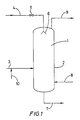
- the reactor shown diagrammatically in Figure 1 can be employed for implementing the invention.
- the temperature of the liquid hydrocarbon spray can be advantageously chosen so as to avoid the immediate evaporation of the sprayed liquid when it is introduced into the vapor space of the reactor
- the temperature of the liquid hydrocarbon spray may be preferably lower than that of the liquid phase comprising the liquid boiling hydrocarbon polymerization medium. In most cases it is from 2 to 30°C, preferably from 3 to 15°C, lower than that of the liquid phase comprising the liquid boiling hydrocarbon polymerization medium. In some cases it may also be equal to or higher than the temperature of the liquid phase, but on condition that the liquid hydrocarbon spray does not evaporate inside the spraying device, for example inside nozzles intended to spray the liquid hydrocarbon. In this case it may be from 2 to 30°C, preferably from 3 to 10°C, higher than that of the liquid phase comprising the liquid boiling hydrocarbon polymerization medium.
- the liquid hydrocarbon spray is introduced into the reactor preferably in a pulverized form, in particular in the form of droplets.
- These droplets are intended to fall essentially under gravity through the vapor space into the liquid phase in order to avoid or to inhibit or prevent any foaming phenomenon of the liquid phase comprising the liquid boiling hydrocarbon polymerization medium.
- the droplets may have a dimension which is sufficient to avoid entrainment of the droplets towards the top of the reactor, especially with a gas which can escape through the top of the reactor.
- These droplets advantageously have a mean diameter of between 100 and 2 000 ⁇ m, preferably between 500 and 1 500 ⁇ m.
- the liquid hydrocarbon spray is preferably dispersed uniformly above the liquid phase comprising the liquid hydrocarbon polymerization medium while being directed downwards, that is to say towards the liquid phase.
- the liquid hydrocarbon spray is advantageously introduced with the aid of a spraying device, especially a device having one or more nozzles the purpose of which is to finely spray and uniformly disperse the liquid hydrocarbon above the liquid phase.
- the nozzles are preferably arranged uniformly in the upper part of the reactor which has the vapor space and point vertically downwards. In particular, they may be uniformly arranged horizontally on one or more crown rings or so as to form a gridwork or a system on one or more levels. It is particularly advantageous to obtain droplets which have a sufficient falling velocity to effectively reduce the foaming phenomenon.
- the introduction of the liquid hydrocarbon spray into the vapor space is advantageously performed at least 1 m, preferably at least 1.5 m above the surface of the liquid phase which separates the vapor space from said liquid phase.
- the distance between the spraying device, especially the nozzles and the surface of the liquid phase is advantageously equal to or greater than 1 m and in most cases between 1 and 4 m, especially between 1.5 and 3 m.
- the number of nozzles is a function of the size of the reactor and of the dimensions of the nozzles which determine the flow rate of the liquid hydrocarbon spray.
- the number of nozzles employed is suitably between 1 and 100, preferably between 3 and 10.
- a nozzle generally ends in a fine-spraying orifice which has a diameter that can range from 4 to 50 mm, preferably from 5 to 20 mm.
- the liquid hydrocarbon spray may be a single hydrocarbon or a mixture of liquid hydrocarbons containing, for example, from 3 to 25 carbon atoms.
- the liquid hydrocarbon spray may comprise at least one of the reactant hydrocarbons, especially at least one olefin, for example C 4 olefin, which takes part in the polymerization reaction, e.g. a butene, isobutene or another olefin. It may also comprise at least one inert hydrocarbon such as a linear, cyclic or branched alkane containing, for example, from 3 to 12, preferably from 4 to 6, carbon atoms, e.g.
- the liquid hydrocarbon spray may be a light olefin polymer, especially a C 4 olefin(s) polymer, in particular an oligomer or a mixture of light polymers.
- the light polymer may be a fraction of the polymer manufactured by the polymerization reaction itself and optionally separated by distillation from the liquid phase. It may have a number-average molecular weight of between 100 and 300.
- the liquid hydrocarbon spray may be a mixture of two or more of the abovementioned hydrocarbons, which are chosen especially from reactive hydrocarbons such as olefins, especially C 4 olefins, inert hydrocarbons such as alkanes, especially from C 3 to C 12 , and polymers or oligomers, especially of C 4 olefin(s).
- it may be identical in nature to the liquid phase comprising the liquid hydrocarbon spray polymerization medium and the polymer manufactured and withdrawn from the reactor and a fraction of which may be employed as the liquid hydrocarbon spray.
- the liquid hydrocarbon may be preferably a fraction or all of the fresh olefin(s) liquid feed to the reactor, as described later. It may also be a fraction or all of a liquid obtained by cooling and condensing a condensable gas escaping from the vapor space of the reactor.
- the liquid hydrocarbon spray is advantageously introduced into the reactor at an hourly flow rate which is a function of the surface of the liquid phase to be sprayed in the reactor.
- the surface to be sprayed corresponds generally to the internal area of the cross-section of the reactor at the upper level, where the liquid phase arrives.
- the flow rate of the liquid hydrocarbon spray may correspond, per hour and per square metre of the surface of the liquid phase, to a volume ranging from 0.3 to 3, preferably from 0.4 to 2 and more especially from 0.6 to 1.2 m 3 .
- this flow rate may also be equivalent to a proportion or to all of the flow rate of the fresh olefin(s) liquid feed to the reactor. It may advantageously represent from 5 to 80 %, preferably from 10 to 60 % and more particularly 15 to 40 %, of the flow rate of the fresh olefin(s) liquid feed to the reactor.
- the polymerization reaction may be performed batchwise or preferably continuously.
- the polymerization temperature is in general between -30°C and +50°C, preferably between -20°C and +25°C.
- the absolute pressure in the reactor is a function of the polymerization temperature and can range from 0.03 to 1, preferably from 0.05 to 0.5 MPa.
- the boiling liquid hydrocarbon polymerization medium suitably contains the olefin or the olefins, especially C 4 olefins, to be polymerized, polymer being formed, catalyst and optionally cocatalyst and saturated hydrocarbons such as alkanes or cycloalkanes.
- a fresh olefin(s) liquid feed containing the olefin(s) to be polymerized is introduced into the reactor.
- the olefin to be polymerized is at least one C 4 olefin, that is to say a butene, especially isobutene.
- the feed in general consists of a mixture of C 4 olefins, that is to say a mixture of butenes.
- Such a mixture may include, by weight, from 1 to 40 %, preferably from 3 to 30 % of 1-butene, from 5 to 20 %, preferably from 10 to 15 % of cis 2-butene, from 5 to 40 %, preferably from 10 to 30 % of trans 2-butene and from 15 to 60 %, preferably from 20 to 50 % of isobutene
- the fresh olefin(s) liquid feed may additionally contain one or more alkanes or cycloalkanes such as eg the butanes.
- the fresh olefin(s) liquid feed may contain from 60 to 95 % by weight of a mixture of butenes and/or isobutene such as those described above, and from 5 to 40 % of C 4 alkanes.
- the fresh olefin(s) liquid feed may be introduced directly into the liquid phase. It may also be introduced into the liquid phase as an admixture with any other liquid introduced into the reactor, for example with a liquid obtained by cooling and condensing condensable gas escaping from the vapor space of the reactor and returned into the reactor.
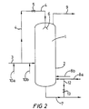
- the fresh olefin(s) liquid feed may also be introduced wholly into the vapor space as liquid hydrocarbon spray. A portion of the fresh olefin(s) liquid feed may be advantageously introduced into the liquid phase and another portion into the vapor space as liquid hydrocarbon spray. To do this, it is possible to employ the device shown diagrammatically in Figure 2.
- the fresh olefin(s) liquid feed employed partially or wholly as liquid hydrocarbon spray may be introduced into the vapor space at the side or through the top of the reactor, by opening the stopcock (5) of the conduit (4) as shown in Figure 2.
- the liquid hydrocarbon spray may have a composition that is identical with the fresh olefin(s) liquid feed. It may consist of a portion or of all of the fresh olefin(s) liquid feed and may be introduced preferably continuously into the vapor space of the reactor, particularly when a continuous polymerization is carried out.
- the fresh olefin(s) liquid feed may be preferably at a temperature that is lower than or equal to that of the liquid phase comprising the liquid boiling hydrocarbon polymerization medium.
- the liquid phase may be agitated by any known means, especially with the aid of a stirrer.
- the agitation of the liquid phase may also be produced by forced circulation of said liquid phase, which may include the withdrawing and the reintroduction of a portion of the liquid phase, especially with the aid of a so-called recycle pump.
- the liquid hydrocarbon spray may be a portion of the liquid phase withdrawn from the reactor and returned to said reactor, preferably continuously, into the vapor space, optionally after cooling.
- the device shown diagrammatically in Figure 3 may be employed to carry out this operation.
- the vapor space of the reactor may comprise a gas phase that is, in particular, condensable.
- a condensable gas can escape from the vapor space of the reactor
- this gas is condensed outside the reactor, in particular in order to remove the heat of the polymerization reaction according to an auto refrigerating system. After cooling and condensation of this gas as a liquid, it can be recovered and recycled into the vapor space and/or into the liquid, phase. A portion or all of the fresh olefin(s) liquid feed may be added to this liquid.
- the liquid thus condensed and recycled is preferably introduced into the vapor space as a liquid hydrocarbon spray and, in particular, continuously, when a continuous polymerization is carried out.
- the liquid hydrocarbon spray may consist of all or of a portion of a liquid obtained after cooling and condensation of a condensable gas which escapes from the vapor space of the reactor and returned to said reactor.
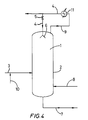
- this alternative form of the invention may be carried out with the aid of the device shown diagrammatically in Figure 4.
- a catalyst which is suited to a cationic polymerization of olefins, including a cationic catalyst and optionally a cocatalyst, is employed.
- the catalyst may be a halogen-containing compound of boron e.g. boron trifluoride or an organoluminium compound, for example of formula AlR n X n-3 in which R is an alkyl radical containing, for example, from 1 to 10 carbon atoms, X is chlorine or bromine and n is a whole number or fraction ranging from 0 to 3.
- the cocatalyst may be hydrochloric acid, an alkyl halide e.g. tert-butyl chloride, water or an alcohol such as ethanol, in particular when boron trifluoride is employed as catalyst, in particular with the catalyst system of formula BF 3 , C 2 H 5 OH.
- the polymerization reaction may be performed with the aid of an alkyl halide as cocatalyst according to the process described in the prior published European Patent Application EP-A-0 645 402, especially with the catalyst system including ethyldichloroaluminium and tert-butyl chloride.
- the molar ratio of the cocatalyst to the catalyst is advantageously between 0.05 and 20, preferably between 1 and 10.
- the catalyst and the cocatalyst are preferably introduced into the reactor separately.
- One of the components of the catalyst system may be introduced in the fresh olefin(s) liquid feed or in the liquid hydrocarbon spray.
- a portion or all of the cocatalyst or of the catalyst may be introduced into the reactor as a mixture with another liquid hydrocarbon, in particular with a polymer present, for example, in a portion of the liquid phase comprising the liquid hydrocarbon polymerization medium, which is withdrawn and recycled in order to provide agitation of the liquid phase of the reactor.
- the process of the invention is particularly suitable for the manufacture of liquid polybutenes or polyisobutenes.
- These polybutenes or polyisobutenes may have a viscosity at 100°C ranging from 20 to 50 000 centiStokes (cSt), preferably from 30 to 5 000 cSt, and a number-average molecular weight ranging from 150 to 11 000, preferably from 500 to 5 500 dalton. They may contain from 3 to 200, preferably from 10 to 100 units derived from a butene monomer. They contain approximately 1 unsaturation per mole and in particular from 0.02 to 0.95 unsaturation of vinylidene type and from 0.05 to 0.98 unsaturation of other types.
- the breadth of the molecular mass distribution may range from 1.2 to 2.5, preferably from 1.4 to 2 and especially from 1.5 to 1.7. Furthermore, it preferably contains less than 50 parts by weight per million (ppm) of halogen such as chlorine.
- Figure 1 shows diagrammatically a solution polymerization device with a reactor (1) which essentially comprises a cylindrical part (2).
- the reactor is equipped with a fresh olefin(s) liquid feed conduit (3) which leads into the cylindrical part (2) containing the liquid phase comprising the liquid boiling hydrocarbon polymerization medium, and with a conduit for introducing liquid hydrocarbon spray (4), which leads into the vapor space of the reactor.
- the conduit for introducing liquid hydrocarbon spray (4) is equipped with a valve (5) and ends in a system for spraying or fine spraying (6) including in particular one or more nozzles.
- the reactor is also equipped with a conduit (7) for withdrawing the liquid phase containing the manufactured polymer, with a catalyst feed conduit (8) and with a condensable gas exit conduit (9).
- a conduit for introducing cocatalyst (10) leads into the fresh olefin(s) liquid feed conduit (3).
- FIG. 2 shows diagrammatically a solution polymerization device with which it is possible to employ at least a portion of the fresh olefin(s) liquid feed as liquid hydrocarbon spray.
- This device is identical with that in Figure 1, except for the fact that the conduit for introducing liquid hydrocarbon spray (4) connects the fresh olefin(s) liquid feed conduit (3) to the spraying or pulverizing system (6).
- two conduits for introducing cocatalyst (10a) and (10b) lead into the conduit (3).
- a portion of the liquid phase withdrawn through the conduit (7) is recycled by a conduit (12) fitted with a stopcock (13), into the liquid phase of the reactor in order to provide agitation.
- Catalyst feed conduits (8a) and (8b) lead into the conduit (12) and into the cylindrical part (2) of the reactor.
- Figure 3 shows diagrammatically a solution polymerization device with which it is possible to employ a portion of the liquid phase containing the manufactured polymer, which is withdrawn from the reactor and reintroduced as liquid hydrocarbon spray.
- This device is identical with that in Figure 1, except for the fact that the conduit for introducing liquid hydrocarbon spray (4) connects the conduit for withdrawing (7) to the spraying or pulverizing system (6) and that a portion of the liquid phase.
- withdrawn through the conduit (7) is recycled through a conduit (12) fitted with a stopcock (13) into the liquid phase of the reactor to provide agitation, the catalyst feed conduit (8) leading into the conduit (12).
- Figure 4 shows diagrammatically a solution polymerization device with which it is possible to employ a liquid obtained after cooling and condensation of a condensable gas which escapes from the vapor space of the reactor and which is recycled as a liquid hydrocarbon spray.
- This device is identical with that described in respect of Figure 1, except for the fact that the conduit for introducing liquid hydrocarbon spray (4) connects the condensable gas exit conduit (9) to the spraying or pulverizing system (6) and that the condensable gas exit conduit is fitted with a cooling and condensing system (11) intended to cool and condense the condensable gas escaping from the vapor space of the reactor.
- a process for continuous polymerization of olefin(s), especially C 4 olefin(s), is preferably carried out, which means that the fresh olefin(s) liquid feed, as well as the liquid hydrocarbon spray and the catalyst and optionally the cocatalyst are continuously introduced into the reactor and the liquid phase containing the manufactured polymer is withdrawn continuously from the reactor.
- a portion of the liquid phase withdrawn from the reactor and containing the manufactured polymer may be advantageously continuously recycled directly into the liquid phase of the reactor to provide agitation, and/or preferably into the vapor space of the reactor as liquid hydrocarbon spray.
- the condensable gas escaping from the vapor space of the reactor may be advantageously recycled at least partly and continuously after cooling and condensation, as liquid hydrocarbon spray into the vapor space of the reactor.
- the present invention also relates to a process for the polymerization of olefin(s), for example C 4 olefin(s), carried out in solution, in the presence of a cationic catalyst, in a reactor containing a liquid phase comprising a boiling liquid hydrocarbon polymerization medium and a vapor space above said liquid phase, characterized in that the polymerization is carried out in the presence of a fresh olefin(s) liquid feed introduced into the reactor at a temperature lower than that of the liquid phase.
- a continuous polymerization is carried out and the fresh olefin(s) liquid feed is continuously introduced into the reactor.
- the invention also relates to a process for narrowing down the molecular weight distribution of a polyolefin obtained by the polymerization of olefin(s), especially C 4 olefin(s), carried out in solution, in a reactor containing a liquid phase comprising a boiling liquid hydrocarbon polymerization medium and a vapor space above said liquid phase, in the presence of a cationic catalyst, characterized in that a fresh olefin(s) liquid feed at a temperature lower than that of the liquid phase is introduced into the reactor.
- the polymerization process is carried out continuously and the fresh olefin(s) liquid feed is continuously introduced into the reactor.
- a fresh olefin(s) liquid feed which has a temperature lower than that of the liquid phase, is introduced into the reactor in order to avoid or to stop any foaming phenomenon in the liquid phase and thus to make it possible to conduct a solution polymerization in stable conditions and to manufacture a polymer of a uniform, and even improved, quality, with a narrow molecular weight distribution.
- the temperature of the fresh olefin(s) liquid feed is in most cases from 2 to 30°C, preferably from 3 to 15°C, lower than that of the liquid phase.
- a heat exchanger is generally employed, intended to cool the fresh olefin(s) liquid feed and to bring it to the desired temperature.
- the polymerization temperature that is to say the temperature of the liquid phase is, in general, between -30°C and +50°C, preferably between -20°C and +25°C.
- the temperature may thus be negative and be, for example, between -30°C and 0°C.
- it is preferably positive and advantageously higher than 0°C and lower than +50°C, and preferably higher than 0°C and lower than +25°C.
- the fresh olefin(s) liquid feed contains the olefin(s) to be polymerized.
- the fresh olefin(s), in particular C 4 olefin(s), liquid feed may be introduced into the reactor with the aid of a pump and of a control system without resulting in a partial evaporation in particular in the line for feeding olefin(s) to the reactor.
- the fresh olefin(s) liquid feed may be introduced directly into the liquid phase It may also be introduced into the liquid phase for example by addition to any other liquid introduced into the reactor, especially to a liquid obtained by cooling and condensing condensable gas escaping from the vapor space of the reactor and returned into the reactor.
- the fresh olefin(s) liquid feed may also be introduced into the vapor space as liquid hydrocarbon spray. It is also possible advantageously to introduce a portion of the fresh olefin(s) liquid feed into the liquid phase and another portion into the vapor space.
- the introduction of the fresh olefin(s) liquid feed into the vapor space may take place at the side or through the top of the reactor.
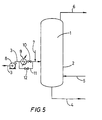
- FIG. 5 shows diagrammatically a solution polymerization device with a reactor (1) which comprises essentially a cylindrical part (2).
- the reactor is equipped with a fresh olefin(s) liquid feed conduit (3) which leads into the cylindrical part (2).
- the feed conduit (3) is fitted with a pump (8) and, at the pump delivery, with a heat exchanger (9) intended to cool the fresh olefin(s) liquid feed to the desired temperature.
- the feed conduit (3) is also fitted with a device for controlling the temperature of the fresh olefin(s) liquid feed, which comprises, at the exit of the heat exchanger (9), a stopcock (10) and a conduit (11) fitted with a stopcock (12) as a bypass of the heat exchanger (9) and of the stopcock (10) in order to bypass the said exchanger at will and to control accurately the temperature of the fresh olefin(s) liquid feed.
- the reactor is also equipped with a conduit (4) for withdrawing the liquid phase containing the manufactured polymer, a catalyst feed conduit (5) and an exit conduit (6) for a condensable gas which may be cooled, condensed and recycled in liquid form into the reactor.
- a conduit for introducing cocatalyst (7) leads into the fresh olefin(s) liquid feed conduit (3).
- the present invention relates to a process for the polymerization of olefin(s), for example C 4 olefin(s), carried out in solution, in the presence of a cationic catalyst, in a reactor containing a liquid phase comprising a boiling liquid hydrocarbon polymerization medium and a vapor space above said liquid phase, characterized in that the polymerization is carried out in the presence of a chemical foam-suppressor.
- the invention also relates to a process for narrowing down the molecular weight distribution of a polyolefin obtained by the polymerization of olefin(s), especially C 4 olefin(s), preferably continuously, carried out in solution, in a reactor containing a liquid phase comprisingly a boiling liquid hydrocarbon polymerization medium and a vapor space above said liquid phase, in the presence of a cationic catalyst, characterized in that the polymerization is carried out in the presence of a chemical foam-suppressor which is introduced into the reactor, preferably continuously, when a continuous polymerization is carried out.
- the polymerization reaction is carried out in the presence of a chemical foam-suppressor. Any foaming phenomenon in the liquid phase can thus be avoided or stopped. What is more, it is then possible to conduct such a solution polymerization in stable conditions and to manufacture a polyolefin of uniform, and even improved, quality, which has in particular a narrow molecular weight distribution.
- the chemical foam-suppressor may be a chemical foam-suppressor known as such. It may be a polyoxyalkylene glycol, also called polyether, obtained by (co)polymerization of one or more epoxides e.g. ethylene oxide, propylene oxide or butene oxide and having, for example, a weight-average molecular weight of ranging from 800 to 5 000 dalton.
- the polyoxyalkylene glycol may be a polyoxyethylene glycol or preferably a polyoxypropylene glycol.
- a block polyoxyalkylene glycol which comprises at least two blocks of different epoxides is advantageously employed.
- This block polyoxyalkylene glycol may comprise a block based on ethylene oxide units and a block based on propylene oxide units. It may, in particular, contain from 1 to 40 % of units derived from ethylene oxide and from 60 to 99 % of units derived from propylene oxide.
- the polyoxyalkylene glycol may be optionally fluorinated or perfluorinated. It may be a polyoxyalkylene glycol sold by B.P. Chemicals Ltd (U.K.) under the trade name Breox ® or by BASF under the trade name Pluronic ®.
- the chemical foam-suppressor is a silicone and more particularly a polysiloxane.
- Silicone is generally intended to mean compounds corresponding to the general formula R-SiO-R' in which R and R', which are identical or different, denote alkyl radicals, for example from C 1 to C 12 , especially from C 1 to C 6 , aryl radicals, for example from C 6 to C 10 , or aralkyl radicals, for example from C 7 to C 14 .
- Polysiloxane is generally intended to mean polymers which have a monomer unit corresponding to the general formula in which R and R' are defined as above. It is preferred to employ a polysiloxane such as a diphenylpolysiloxane or a dimethylpolysiloxane.
- the silicone and, in particular, the polysiloxane may have a kinetic viscosity at 25°C ranging from 5 to 1 000 000 centiStokes (cSt), preferably from 5 000 to 7 000 000 cSt, and more particularly from 6 000 to 30 000 cSt.
- cSt centiStokes
- the concentration of chemical foam-suppressor in the liquid phase of the reactor may range from 0.01 to 100, preferably from 0.1 to 10 parts by weight per million (ppm) in relation to the liquid phase.
- the chemical foam-suppressor may be used as it is or in the form of a solution
- the solution may be in a liquid hydrocarbon in a concentration which may range from 2 to 50 % by weight.
- This liquid may be a liquid hydrocarbon or a mixture of liquid hydrocarbons containing, for example, from 3 to 25 carbon atoms.
- the liquid hydrocarbon may be at least one reactive hydrocarbon e.g. one or more olefins such as a butene or isobutene.
- the hydrocarbon may also be at least one inert hydrocarbon e.g. a linear, branched or cyclic alkane which may have from 3 to 12, preferably from 4 to 6, carbon atoms, e.g.
- the liquid hydrocarbon may be at least one light polymer, in particular an oligomer, or a mixture of light polymers, for example of butene or of isobutene, which may originate from the polymerization reaction itself, optionally after they have been separated off by distillation, and which may have a number-average molecular weight, M n , ranging from 100 to 300 dalton.
- the liquid hydrocarbon may be in particular a fresh olefin(s) liquid feed to the reactor, or the liquid phase comprising the liquid hydrocarbon polymerization medium itself, especially when a portion of the liquid phase is withdrawn from the reactor and reintroduced into the latter for the purpose of providing sufficient agitation of the liquid phase, or else a liquid obtained by cooling and condensation of condensable gas escaping through the vapor space of the reactor and returned into the reactor.
- the chemical foam-suppressor may be introduced preferably continuously into the reactor, during a continuous polymerization process. Its introduction can take place at one or more points of the reactor. It may take place directly with the aid of a conduit which leads sideways into the reactor or through the bottom or else through the top of the polymerization reactor. It may take place indirectly by introducing the chemical foam-suppressor into a reactor feed conduit, especially into the fresh olefin(s) liquid feed conduit.
- the chemical foam-suppressor may be introduced into the reactor directly into the liquid phase and/or into the vapor space above said liquid phase, for example by spraying.
- the chemical foam-suppressor may be introduced at a temperature which is preferably lower than that of the liquid phase, especially in order to avoid a premature evaporation of the liquid employed to form the solution of the chemical foam-suppressor. It may thus be introduced at a temperature which is from 2 to 30°C, preferably from 3 to 15°C lower than that of the liquid phase of the reactor. In some cases it may also be introduced at a temperature which is higher than that of the liquid phase, but on condition that an evaporation such as that mentioned above is avoided.
- the chemical foam-suppressor may be introduced into the reactor in the form of a mixture with the catalyst and/or the cocatalyst.
- the polymerization is advantageously carried out continuously.
- the fresh olefin(s) liquid feed, the chemical foam-suppressor and the catalyst and optionally the cocatalyst are introduced into the reactor continuously.
- the liquid phase containing the manufactured polymer is itself withdrawn continuously from the reactor, it being possible for a portion of said liquid phase to be continuously returned into the reactor to maintain agitation in the liquid phase, and it being possible for the chemical foam-suppressor to be preferably continuously added to this portion which is continuously returned into the reactor.
- at least a portion of a condensable gas escaping from the vapor space of the reactor may leave the reactor and be returned, preferably continuously, into the reactor after cooling and condensation in the form of a liquid.
- the chemical foam-suppressor and optionally the fresh olefin(s) liquid feed may be preferably continuously added to this liquid which is returned into the reactor.
- the polymerization is preferably carried out with agitation, for example with mechanical stirring or with agitation created by forced recirculation of a portion of the liquid phase withdrawn from the reactor and reintroduced, for example, with the aid of a pump.
- the chemical foam-suppressor may also be added to this forced liquid recirculation.
- Figure 6 shows diagrammatically a device for the solution polymerization of olefin(s), including a reactor (1) comprising essentially of a cylindrical part (2).
- the reactor (1) is equipped with a fresh olefin(s) liquid feed conduit (3) which leads into the cylindrical part (2).
- the fresh olefin(s) liquid feed conduit (3) is equipped with a cocatalyst feed conduit (4) and a chemical foam-suppressor feed conduit (5).
- the reactor is also equipped with a conduit for withdrawing the liquid phase comprising polymer (6), a catalyst feed conduit (7) and an exit conduit (8) for condensable gas, which may be cooled, condensed and recycled in liquid form into the reactor.
- the breath of the molecular weight distribution of the polybutenes or polyisobutenes is calculated as the ratio of the weight-average molecular weight, M w , to the number-average molecular weight, M n , from a curve obtained using a Waters ® G.P.C. apparatus equipped with a refractometer detector.
- the apparatus includes a Waters 717 Plus ® automatic injection system, a Waters 610 ® pump and a set of 4 Waters Ultrastyragel ® columns of 10000, 1 000, 500 and 100 porosity, 25 cm in length, which are mounted in series.
- the operating conditions are the following:
- a device for continuous solution polymerization as shown diagrammatically in Figure 2 is employed, including a reactor (1) comprising of a cylindrical part (2).
- the spraying system (6) includes 6 "SC10N” ® nozzles sold by Bete Fog Nozzle Inc (USA) which end in a fine-spraying orifice which has a 9.9 mm diameter and which point vertically towards the bottom of the reactor.
- the spraying system is situated 2 m above the surface of the liquid phase separating the vapor space from said liquid phase of the reactor.
- This reactor is fed continuously with fresh olefin(s) through the conduit (3) using a liquid feed containing, by weight, 29 % of 1-butene, 8 % of cis 2-butene, 11 % of trans 2-butene, 44 % of isobutene and 8 % of butanes.
- the total flow rate of the fresh olefin(s) liquid feed via the conduit (3) is 38 m 3 /h.
- the liquid hydrocarbon spray consisting of a portion of the fresh olefin(s) liquid feed is introduced continuously into the vapor space of the reactor through the conduit (4) at a flow rate of 10 m 3 /h in the form of droplets which have a mean diameter of 1 000 ⁇ m, while the remainder of the fresh olefin(s) liquid feed is introduced continuously directly into the liquid phase of the reactor at a flow rate of 28 m 3 /h.
- the reaction temperature is + 10°C; the total absolute pressure in the reactor is 0.15 MPa.
- the catalyst system includes tert-butyl chloride as cocatalyst and ethyldichloroaluminium as catalyst in a molar ratio of 4.1:1 respectively.
- the cocatalyst is introduced continuously into the fresh olefin(s) liquid feed conduit (3) with the aid of the conduit (10a) at a flow rate of 8 kg/h, and the catalyst into the recycle conduit (12) with the aid of the conduit (8a).
- Example 2 The operation is carried out exactly as in Example 1, with the exception that the valve (5) is closed and that therefore all of the fresh olefin(s) liquid feed is introduced directly into the liquid phase of the reactor at a flow rate of 38 m 3 /h.
- a polymerization is carried out in relatively unstable conditions with, in particular, problems of loss of priming of a pump (not shown in Figure 2) in the conduit for withdrawal (7) of the polymer.
- 10 t/h are obtained of a polyisobutene which has a molecular weight distribution breadth of 1.85 and a chlorine content higher than 25 ppm.
- considerable foaming of the liquid phase is observed, which manifests itself in the presence of a foam that occupies the entire volume of the reactor and the relative density of which from the top towards the bottom of the reactor ranges from 0.1 to 0.5.
- a solution polymerization device as shown diagrammatically in Figure 5 is employed, including a reactor (1) comprising of a cylindrical part (2).
- This reactor is fed continuously with fresh olefin(s) through the conduit (3) using a fresh olefin(s) liquid feed containing, by weight, 29 % of 1-butene, 8 % of cis 2-butene, 11 % of trans 2-butene, 44 % of isobutene and 8 % of butanes.
- the fresh olefin(s) liquid feed is continuously cooled to +5°C with the aid, in particular, of the heat exchanger (9).
- the fresh olefin(s) liquid feed rate is 38 m 3 /h.
- the temperature of the polymerization reaction that is to say the temperature of the liquid phase, is +10°C.
- the total absolute pressure in the reactor is 0.15 MPa.
- the catalyst system includes tert-butyl chloride as cocatalyst and ethyldichloroaluminium as catalyst in a molar ratio of 4.1:1 respectively.
- the cocatalyst is introduced into the fresh olefin(s) liquid feed conduit (3) with the aid of the conduit (7) at a flow rate of 8 kg/h.
- the catalyst is introduced into the reactor through the conduit (5).
- Example 3 The operation is carried out exactly as in Example 3, except that the fresh olefin(s) liquid feed is not cooled. It is introduced into the reactor at ambient temperature (+20°C).
- a polymerization is thus carried out in relatively unstable conditions, in particular with problem, of loss of priming of a pump (not shown in Figure 5) in the polymer withdrawal conduit (4).
- a solution polymerization reactor such as that shown diagrammatically in Figure 6, comprising of a cylindrical part (2), is employed.
- This reactor is fed through the conduit (3) with a fresh olefin(s) liquid feed containing, by weight, 29 % of 1-butene, 8 % of cis 2-butene, 11 % of trans 2-butene, 44 % of isobutene and 8 % of butanes.
- the fresh olefin liquid feed rate is 38 m 3 /h.
- the chemical foam-suppressor "Viscasil 12 M”® which has a kinematic viscosity at 25°C of 12 500 cSt, is introduced into the reactor through the conduit (5) at a flow rate of 110 g/h.
- the reaction temperature is + 10°C
- the total absolute pressure in the reactor is 0.15 MPa.
- the catalyst system includes tert-butyl chloride as cocatalyst and ethyldichloroaluminium as catalyst in a molar ratio of 4.1:1 respectively.
- the cocatalyst is introduced into the reactor through the conduit (4) at a flow rate of 8 kg/h and the catalyst is introduced through the conduit (7).
- Example 5 The operation is carried out exactly as in Example 5, except for the fact that no chemical foam-suppressor is introduced.
Landscapes
- Chemical & Material Sciences (AREA)
- Chemical Kinetics & Catalysis (AREA)
- Organic Chemistry (AREA)
- Health & Medical Sciences (AREA)
- Medicinal Chemistry (AREA)
- Polymers & Plastics (AREA)
- Dispersion Chemistry (AREA)
- Addition Polymer Or Copolymer, Post-Treatments, Or Chemical Modifications (AREA)
- Polymerisation Methods In General (AREA)
- Transition And Organic Metals Composition Catalysts For Addition Polymerization (AREA)
Description
- The present invention relates to a process for the polymerization of olefin(s) which is particularly suitable for the manufacture of polybutene or polyisobutene.
- It is known to polymerize a mixture of butenes in solution in a boiling liquid hydrocarbon polymerization medium, especially for manufacturing a liquid polybutene or polyisobutene. In general the solution polymerization is carried out continuously in a reactor with the aid of a catalyst of cationic type and optionally of a cocatalyst. A reaction instability has very frequently been observed in the polymerization reactor in such a process. This instability can be characterized especially by the manufacture of a polymer of a nonuniform quality, which has a molecular weight distribution which is too broad, generally with catalyst residues or chlorine residues in a quantity which is too large. It may also be characterized by difficulties in control of some polymerization parameters, such as the polymerization temperature, the mean residence time of the polymer in the reactor or the withdrawal of the polymer out of the reactor.
- After long studies it has surprisingly been found that these problems were linked with the presence of a foam which forms above the reaction liquid phase and which occupies a large proportion or even the whole of the reactor volume. This foam formation causes an instability of the reaction and a heterogeneity of the liquid hydrocarbon polymerization medium, which is reflected especially in a density gradient. These phenomena thus promote the production of a polybutene or polyisobutene of poor quality, which has in particular a breadth of the molecular weight distribution which is too broad and not compatible with some applications. Furthermore, the utilization of such a process is made difficult, for example, by loss of priming of the pumps which convey the liquid hydrocarbon polymerization medium, especially a loss of priming of the pump for withdrawing the polymer.
- A process has now been found which allows the abovementioned problems to be solved. In particular the process makes it possible to manufacture, in improved reaction stability conditions, a polybutene or polyisobutene of a stable and desired quality, which has in particular a narrow molecular weight distribution generally with a very low catalyst residue or chlorine content.
- The process of the invention permits a stabilization of the polymerization reaction and hence better control of this reaction. Furthermore, taking into account the fact that the polymerization reaction is stabilized, the liquid hydrocarbon polymerization medium is more homogeneous. As a result, the mean residence time of the polymer in the polymerization reactor can be decreased. The process of the invention can thus permit an increase in the polymer production capacity of the reactor.
- The present invention relates therefore to a process for producing an olefin polymer of a low polydispersity index (i.e. a narrow molecular weight distribution) having low catalyst residues and/or low chlorine content by the polymerization of olefin(s), especially C4 olefin(s), said process being carried out in solution, in the presence of a cationic catalyst, in a reactor containing a liquid phase comprising a liquid boiling hydrocarbon polymerization medium and having a vapor space above said liquid phase, characterized in that the polymerization is carried out in the presence of a non-mechanical agent capable of suppressing foam formation during said polymerization.
- The present invention also relates to a process for reducing the polydispersity index of an olefin polymer having low catalyst residues and/or low chlorine content in a solution polymerization of olefin(s), especially C4 olefin(s), said process being carried out in the presence of a cationic catalyst in a reactor containing a liquid phase comprising a liquid boiling hydrocarbon polymerization medium and having a vapor space above said liquid phase, characterized in that the polymerization is carried out in the presence of a non-mechanical agent capable of suppressing foam formation during said polymerization.
- More particularly the agent capable of suppressing foam in the present invention excludes the use of a mechanical means e.g. stirring for imparting shearing forces to foam accumulating in the vapor space of the reactor.
- According to a first embodiment of the present invention, the agent capable of suppressing foam formation preferably is a liquid hydrocarbon spray introduced into the vapor space above the liquid phase in the reactor.
- Figures 1 to 4 show diagrammatically various devices for implementing the process of the invention using a liquid hydrocarbon spray.
- According to a second embodiment of the present invention, the agent capable of suppressing foam formation is a fresh olefin liquid feed introduced into the reactor at a temperature lower than that of the liquid phase comprising the liquid boiling hydrocarbon polymerization medium.
- Figure 5 shows diagrammatically a device for implementing the process of the invention using a fresh olefin liquid feed at a temperature lower than that of the liquid phase.
- According to a third embodiment of the present invention, the agent capable of suppressing foam formation is a chemical foam-suppressor.
- Figure 6 shows diagrammatically a device for implementing the process of the invention using a chemical foam-suppressor.
- The present invention preferably relates a process for producing an olefin polymer of a low polydispersity index (i.e. a narrow molecular weight distribution) having low catalyst residues and/or low chlorine content by the polymerization of olefin(s), especially C4 olefin(s), said process being carried out in solution, in the presence of a cationic catalyst, in a reactor containing a liquid phase comprising a liquid boiling hydrocarbon polymerization medium and having a vapor space above said liquid phase, characterized in that the polymerization is carried out in the presence of an agent selected from (a) a liquid hydrocarbon spray introduced into the vapor space above the liquid phase in the reactor, (b) a fresh olefin liquid feed introduced into the reactor at a temperature lower than that of said liquid phase, and (c) a chemical foam-supressor.
- Preferably the present invention also relates to a process for reducing the polydispersity index of an olefin polymer having low catalyst residues and/or low chlorine content in a solution polymerization of olefin(s), especially C4 olefin(s), said process being carried out in the presence of a cationic catalyst in a reactor containing a liquid phase comprising a liquid boiling hydrocarbon polymerization medium and having a vapor space above said liquid phase, characterized in that the polymerization is carried out in the presence of an agent selected from (a) a liquid hydrocarbon spray introduced into the vapor space above the liquid phase in the reactor, (b) a fresh olefin liquid feed introduced into the reactor at a temperature lower than that of said liquid phase, and (c) a chemical foam supressor.
- In the first embodiment, the present invention relates therefore to a process for a solution polymerization of olefin(s), especially C4 olefin(s), carried out in the presence of cationic catalyst, in a reactor containing a liquid phase comprising a boiling liquid hydrocarbon polymerization medium and having a vapor space above said liquid phase, characterized in that the polymerization is carried out in the presence of a liquid hydrocarbon spray introduced into the vapor space above the liquid phase in the reactor.
- According to one particular aspect, the invention also relates to a process for narrowing down the molecular weight distribution of a polyolefin obtained by continuous polymerization of olefin(s), especially C4 olefin(s), carried out in solution, in a reactor containing a liquid phase comprising a boiling liquid hydrocarbon polymerization medium and having a vapor space above said liquid phase in the presence of a cationic catalyst, characterized in that the polymerization is carried out in the presence a liquid hydrocarbon spray introduced into the vapor space of the reactor, preferably continuously.
- According to the invention, at least one liquid hydrocarbon spray is introduced into the vapor space of the reactor. As a result, any phenomenon of foaming of the liquid phase can thus be avoided or stopped and the polymerization solution can be conducted in stable conditions and a polymer of a uniform and even improved quality can be manufactured. The detection of possible foaming can be performed with the aid of a series of pressure sensors, for example by measuring the pressure difference between the top and the bottom of the reactor, or by measurements of absorption of a gamma radiation which are performed at different heights of the reactor.
- The liquid hydrocarbon spray is not introduced directly into the liquid phase, but into the vapor space of the reactor, preferably continuously and especially at one or more points situated above the surface of the liquid phase which separates the vapor space from said liquid phase. Its introduction can take place at the side or preferably through the top of the polymerization reactor, especially vertically above the liquid phase. By way of example, the reactor shown diagrammatically in Figure 1 can be employed for implementing the invention.
- The temperature of the liquid hydrocarbon spray can be advantageously chosen so as to avoid the immediate evaporation of the sprayed liquid when it is introduced into the vapor space of the reactor To do this, the temperature of the liquid hydrocarbon spray may be preferably lower than that of the liquid phase comprising the liquid boiling hydrocarbon polymerization medium. In most cases it is from 2 to 30°C, preferably from 3 to 15°C, lower than that of the liquid phase comprising the liquid boiling hydrocarbon polymerization medium. In some cases it may also be equal to or higher than the temperature of the liquid phase, but on condition that the liquid hydrocarbon spray does not evaporate inside the spraying device, for example inside nozzles intended to spray the liquid hydrocarbon. In this case it may be from 2 to 30°C, preferably from 3 to 10°C, higher than that of the liquid phase comprising the liquid boiling hydrocarbon polymerization medium.
- The liquid hydrocarbon spray is introduced into the reactor preferably in a pulverized form, in particular in the form of droplets. These droplets are intended to fall essentially under gravity through the vapor space into the liquid phase in order to avoid or to inhibit or prevent any foaming phenomenon of the liquid phase comprising the liquid boiling hydrocarbon polymerization medium. As a result, the droplets may have a dimension which is sufficient to avoid entrainment of the droplets towards the top of the reactor, especially with a gas which can escape through the top of the reactor. These droplets advantageously have a mean diameter of between 100 and 2 000 µm, preferably between 500 and 1 500 µm.
- According to the invention the liquid hydrocarbon spray is preferably dispersed uniformly above the liquid phase comprising the liquid hydrocarbon polymerization medium while being directed downwards, that is to say towards the liquid phase. The liquid hydrocarbon spray is advantageously introduced with the aid of a spraying device, especially a device having one or more nozzles the purpose of which is to finely spray and uniformly disperse the liquid hydrocarbon above the liquid phase. The nozzles are preferably arranged uniformly in the upper part of the reactor which has the vapor space and point vertically downwards. In particular, they may be uniformly arranged horizontally on one or more crown rings or so as to form a gridwork or a system on one or more levels. It is particularly advantageous to obtain droplets which have a sufficient falling velocity to effectively reduce the foaming phenomenon. Thus, the introduction of the liquid hydrocarbon spray into the vapor space is advantageously performed at least 1 m, preferably at least 1.5 m above the surface of the liquid phase which separates the vapor space from said liquid phase. In practice the distance between the spraying device, especially the nozzles and the surface of the liquid phase is advantageously equal to or greater than 1 m and in most cases between 1 and 4 m, especially between 1.5 and 3 m.
- The number of nozzles is a function of the size of the reactor and of the dimensions of the nozzles which determine the flow rate of the liquid hydrocarbon spray. The number of nozzles employed is suitably between 1 and 100, preferably between 3 and 10. A nozzle generally ends in a fine-spraying orifice which has a diameter that can range from 4 to 50 mm, preferably from 5 to 20 mm.
- According to the invention the liquid hydrocarbon spray may be a single hydrocarbon or a mixture of liquid hydrocarbons containing, for example, from 3 to 25 carbon atoms. The liquid hydrocarbon spray may comprise at least one of the reactant hydrocarbons, especially at least one olefin, for example C4 olefin, which takes part in the polymerization reaction, e.g. a butene, isobutene or another olefin. It may also comprise at least one inert hydrocarbon such as a linear, cyclic or branched alkane containing, for example, from 3 to 12, preferably from 4 to 6, carbon atoms, e.g. a butane, a pentane, a hexane or cyclohexane. The liquid hydrocarbon spray may be a light olefin polymer, especially a C4 olefin(s) polymer, in particular an oligomer or a mixture of light polymers. The light polymer may be a fraction of the polymer manufactured by the polymerization reaction itself and optionally separated by distillation from the liquid phase. It may have a number-average molecular weight of between 100 and 300. The liquid hydrocarbon spray may be a mixture of two or more of the abovementioned hydrocarbons, which are chosen especially from reactive hydrocarbons such as olefins, especially C4 olefins, inert hydrocarbons such as alkanes, especially from C3 to C12, and polymers or oligomers, especially of C4 olefin(s). In particular, it may be identical in nature to the liquid phase comprising the liquid hydrocarbon spray polymerization medium and the polymer manufactured and withdrawn from the reactor and a fraction of which may be employed as the liquid hydrocarbon spray. The liquid hydrocarbon may be preferably a fraction or all of the fresh olefin(s) liquid feed to the reactor, as described later. It may also be a fraction or all of a liquid obtained by cooling and condensing a condensable gas escaping from the vapor space of the reactor.
- The liquid hydrocarbon spray is advantageously introduced into the reactor at an hourly flow rate which is a function of the surface of the liquid phase to be sprayed in the reactor. The surface to be sprayed corresponds generally to the internal area of the cross-section of the reactor at the upper level, where the liquid phase arrives. More particularly, the flow rate of the liquid hydrocarbon spray may correspond, per hour and per square metre of the surface of the liquid phase, to a volume ranging from 0.3 to 3, preferably from 0.4 to 2 and more especially from 0.6 to 1.2 m3. Furthermore, this flow rate may also be equivalent to a proportion or to all of the flow rate of the fresh olefin(s) liquid feed to the reactor. It may advantageously represent from 5 to 80 %, preferably from 10 to 60 % and more particularly 15 to 40 %, of the flow rate of the fresh olefin(s) liquid feed to the reactor.
- The polymerization reaction may be performed batchwise or preferably continuously. The polymerization temperature is in general between -30°C and +50°C, preferably between -20°C and +25°C. The absolute pressure in the reactor is a function of the polymerization temperature and can range from 0.03 to 1, preferably from 0.05 to 0.5 MPa.
- The boiling liquid hydrocarbon polymerization medium suitably contains the olefin or the olefins, especially C4 olefins, to be polymerized, polymer being formed, catalyst and optionally cocatalyst and saturated hydrocarbons such as alkanes or cycloalkanes.
- A fresh olefin(s) liquid feed containing the olefin(s) to be polymerized is introduced into the reactor. In most cases the olefin to be polymerized is at least one C4 olefin, that is to say a butene, especially isobutene. The feed in general consists of a mixture of C4 olefins, that is to say a mixture of butenes. Such a mixture may include, by weight, from 1 to 40 %, preferably from 3 to 30 % of 1-butene, from 5 to 20 %, preferably from 10 to 15 % of cis 2-butene, from 5 to 40 %, preferably from 10 to 30 % of trans 2-butene and from 15 to 60 %, preferably from 20 to 50 % of isobutene Furthermore, the fresh olefin(s) liquid feed may additionally contain one or more alkanes or cycloalkanes such as eg the butanes. Thus, for example, the fresh olefin(s) liquid feed may contain from 60 to 95 % by weight of a mixture of butenes and/or isobutene such as those described above, and from 5 to 40 % of C4 alkanes.
- The fresh olefin(s) liquid feed may be introduced directly into the liquid phase. It may also be introduced into the liquid phase as an admixture with any other liquid introduced into the reactor, for example with a liquid obtained by cooling and condensing condensable gas escaping from the vapor space of the reactor and returned into the reactor. The fresh olefin(s) liquid feed may also be introduced wholly into the vapor space as liquid hydrocarbon spray. A portion of the fresh olefin(s) liquid feed may be advantageously introduced into the liquid phase and another portion into the vapor space as liquid hydrocarbon spray. To do this, it is possible to employ the device shown diagrammatically in Figure 2. The fresh olefin(s) liquid feed employed partially or wholly as liquid hydrocarbon spray may be introduced into the vapor space at the side or through the top of the reactor, by opening the stopcock (5) of the conduit (4) as shown in Figure 2.
- Consequently, the liquid hydrocarbon spray may have a composition that is identical with the fresh olefin(s) liquid feed. It may consist of a portion or of all of the fresh olefin(s) liquid feed and may be introduced preferably continuously into the vapor space of the reactor, particularly when a continuous polymerization is carried out.
- The fresh olefin(s) liquid feed may be preferably at a temperature that is lower than or equal to that of the liquid phase comprising the liquid boiling hydrocarbon polymerization medium.
- The liquid phase may be agitated by any known means, especially with the aid of a stirrer.
- The agitation of the liquid phase may also be produced by forced circulation of said liquid phase, which may include the withdrawing and the reintroduction of a portion of the liquid phase, especially with the aid of a so-called recycle pump. In this case the liquid hydrocarbon spray may be a portion of the liquid phase withdrawn from the reactor and returned to said reactor, preferably continuously, into the vapor space, optionally after cooling. The device shown diagrammatically in Figure 3 may be employed to carry out this operation.
- The vapor space of the reactor may comprise a gas phase that is, in particular, condensable. As a result, a condensable gas can escape from the vapor space of the reactor In general this gas is condensed outside the reactor, in particular in order to remove the heat of the polymerization reaction according to an auto refrigerating system. After cooling and condensation of this gas as a liquid, it can be recovered and recycled into the vapor space and/or into the liquid, phase. A portion or all of the fresh olefin(s) liquid feed may be added to this liquid. The liquid thus condensed and recycled is preferably introduced into the vapor space as a liquid hydrocarbon spray and, in particular, continuously, when a continuous polymerization is carried out.
- Consequently, according to an alternative form of the invention, the liquid hydrocarbon spray may consist of all or of a portion of a liquid obtained after cooling and condensation of a condensable gas which escapes from the vapor space of the reactor and returned to said reactor. By way of example, this alternative form of the invention may be carried out with the aid of the device shown diagrammatically in Figure 4.
- To carry out the polymerization of the olefin, a catalyst which is suited to a cationic polymerization of olefins, including a cationic catalyst and optionally a cocatalyst, is employed. More particularly, the catalyst may be a halogen-containing compound of boron e.g. boron trifluoride or an organoluminium compound, for example of formula AlRnXn-3 in which R is an alkyl radical containing, for example, from 1 to 10 carbon atoms, X is chlorine or bromine and n is a whole number or fraction ranging from 0 to 3. The cocatalyst may be hydrochloric acid, an alkyl halide e.g. tert-butyl chloride, water or an alcohol such as ethanol, in particular when boron trifluoride is employed as catalyst, in particular with the catalyst system of formula BF3, C2H5OH.
- The polymerization reaction may be performed with the aid of an alkyl halide as cocatalyst according to the process described in the prior published European Patent Application EP-A-0 645 402, especially with the catalyst system including ethyldichloroaluminium and tert-butyl chloride.
- The molar ratio of the cocatalyst to the catalyst is advantageously between 0.05 and 20, preferably between 1 and 10.
- The catalyst and the cocatalyst are preferably introduced into the reactor separately. One of the components of the catalyst system may be introduced in the fresh olefin(s) liquid feed or in the liquid hydrocarbon spray. A portion or all of the cocatalyst or of the catalyst may be introduced into the reactor as a mixture with another liquid hydrocarbon, in particular with a polymer present, for example, in a portion of the liquid phase comprising the liquid hydrocarbon polymerization medium, which is withdrawn and recycled in order to provide agitation of the liquid phase of the reactor.
- The process of the invention is particularly suitable for the manufacture of liquid polybutenes or polyisobutenes. These polybutenes or polyisobutenes may have a viscosity at 100°C ranging from 20 to 50 000 centiStokes (cSt), preferably from 30 to 5 000 cSt, and a number-average molecular weight ranging from 150 to 11 000, preferably from 500 to 5 500 dalton. They may contain from 3 to 200, preferably from 10 to 100 units derived from a butene monomer. They contain approximately 1 unsaturation per mole and in particular from 0.02 to 0.95 unsaturation of vinylidene type and from 0.05 to 0.98 unsaturation of other types. When the number-average molecular weight is from 500 to 5 500 dalton, the breadth of the molecular mass distribution may range from 1.2 to 2.5, preferably from 1.4 to 2 and especially from 1.5 to 1.7. Furthermore, it preferably contains less than 50 parts by weight per million (ppm) of halogen such as chlorine.
- Figure 1 shows diagrammatically a solution polymerization device with a reactor (1) which essentially comprises a cylindrical part (2). The reactor is equipped with a fresh olefin(s) liquid feed conduit (3) which leads into the cylindrical part (2) containing the liquid phase comprising the liquid boiling hydrocarbon polymerization medium, and with a conduit for introducing liquid hydrocarbon spray (4), which leads into the vapor space of the reactor. The conduit for introducing liquid hydrocarbon spray (4) is equipped with a valve (5) and ends in a system for spraying or fine spraying (6) including in particular one or more nozzles. The reactor is also equipped with a conduit (7) for withdrawing the liquid phase containing the manufactured polymer, with a catalyst feed conduit (8) and with a condensable gas exit conduit (9). A conduit for introducing cocatalyst (10) leads into the fresh olefin(s) liquid feed conduit (3).
- Figure 2 shows diagrammatically a solution polymerization device with which it is possible to employ at least a portion of the fresh olefin(s) liquid feed as liquid hydrocarbon spray. This device is identical with that in Figure 1, except for the fact that the conduit for introducing liquid hydrocarbon spray (4) connects the fresh olefin(s) liquid feed conduit (3) to the spraying or pulverizing system (6). Furthermore, two conduits for introducing cocatalyst (10a) and (10b) lead into the conduit (3). A portion of the liquid phase withdrawn through the conduit (7) is recycled by a conduit (12) fitted with a stopcock (13), into the liquid phase of the reactor in order to provide agitation. Catalyst feed conduits (8a) and (8b) lead into the conduit (12) and into the cylindrical part (2) of the reactor.
- Figure 3 shows diagrammatically a solution polymerization device with which it is possible to employ a portion of the liquid phase containing the manufactured polymer, which is withdrawn from the reactor and reintroduced as liquid hydrocarbon spray. This device is identical with that in Figure 1, except for the fact that the conduit for introducing liquid hydrocarbon spray (4) connects the conduit for withdrawing (7) to the spraying or pulverizing system (6) and that a portion of the liquid phase. withdrawn through the conduit (7) is recycled through a conduit (12) fitted with a stopcock (13) into the liquid phase of the reactor to provide agitation, the catalyst feed conduit (8) leading into the conduit (12).
- Figure 4 shows diagrammatically a solution polymerization device with which it is possible to employ a liquid obtained after cooling and condensation of a condensable gas which escapes from the vapor space of the reactor and which is recycled as a liquid hydrocarbon spray. This device is identical with that described in respect of Figure 1, except for the fact that the conduit for introducing liquid hydrocarbon spray (4) connects the condensable gas exit conduit (9) to the spraying or pulverizing system (6) and that the condensable gas exit conduit is fitted with a cooling and condensing system (11) intended to cool and condense the condensable gas escaping from the vapor space of the reactor.
- A process for continuous polymerization of olefin(s), especially C4 olefin(s), is preferably carried out, which means that the fresh olefin(s) liquid feed, as well as the liquid hydrocarbon spray and the catalyst and optionally the cocatalyst are continuously introduced into the reactor and the liquid phase containing the manufactured polymer is withdrawn continuously from the reactor. A portion of the liquid phase withdrawn from the reactor and containing the manufactured polymer may be advantageously continuously recycled directly into the liquid phase of the reactor to provide agitation, and/or preferably into the vapor space of the reactor as liquid hydrocarbon spray. Furthermore, the condensable gas escaping from the vapor space of the reactor may be advantageously recycled at least partly and continuously after cooling and condensation, as liquid hydrocarbon spray into the vapor space of the reactor.
- It follows from this that the process is very particularly suitable for reducing or stopping the foaming phenomena in a continuous solution polymerization of olefin(s), in particular C4 olefins, and that the liquid hydrocarbon spray is introduced continuously into the gas phase of the reactor.
- In a second embodiment, the present invention also relates to a process for the polymerization of olefin(s), for example C4 olefin(s), carried out in solution, in the presence of a cationic catalyst, in a reactor containing a liquid phase comprising a boiling liquid hydrocarbon polymerization medium and a vapor space above said liquid phase, characterized in that the polymerization is carried out in the presence of a fresh olefin(s) liquid feed introduced into the reactor at a temperature lower than that of the liquid phase. Preferably a continuous polymerization is carried out and the fresh olefin(s) liquid feed is continuously introduced into the reactor.
- According to one particular aspect, the invention also relates to a process for narrowing down the molecular weight distribution of a polyolefin obtained by the polymerization of olefin(s), especially C4 olefin(s), carried out in solution, in a reactor containing a liquid phase comprising a boiling liquid hydrocarbon polymerization medium and a vapor space above said liquid phase, in the presence of a cationic catalyst, characterized in that a fresh olefin(s) liquid feed at a temperature lower than that of the liquid phase is introduced into the reactor. Preferably the polymerization process is carried out continuously and the fresh olefin(s) liquid feed is continuously introduced into the reactor.
- According to one aspect of the invention, a fresh olefin(s) liquid feed which has a temperature lower than that of the liquid phase, is introduced into the reactor in order to avoid or to stop any foaming phenomenon in the liquid phase and thus to make it possible to conduct a solution polymerization in stable conditions and to manufacture a polymer of a uniform, and even improved, quality, with a narrow molecular weight distribution.
- The temperature of the fresh olefin(s) liquid feed is in most cases from 2 to 30°C, preferably from 3 to 15°C, lower than that of the liquid phase. A heat exchanger is generally employed, intended to cool the fresh olefin(s) liquid feed and to bring it to the desired temperature.
- Under these circumstances, the polymerization temperature, that is to say the temperature of the liquid phase is, in general, between -30°C and +50°C, preferably between -20°C and +25°C. The temperature may thus be negative and be, for example, between -30°C and 0°C. However, it is preferably positive and advantageously higher than 0°C and lower than +50°C, and preferably higher than 0°C and lower than +25°C.
- As previously mentioned, the fresh olefin(s) liquid feed contains the olefin(s) to be polymerized. In these conditions the fresh olefin(s), in particular C4 olefin(s), liquid feed may be introduced into the reactor with the aid of a pump and of a control system without resulting in a partial evaporation in particular in the line for feeding olefin(s) to the reactor.
- The fresh olefin(s) liquid feed may be introduced directly into the liquid phase It may also be introduced into the liquid phase for example by addition to any other liquid introduced into the reactor, especially to a liquid obtained by cooling and condensing condensable gas escaping from the vapor space of the reactor and returned into the reactor. The fresh olefin(s) liquid feed may also be introduced into the vapor space as liquid hydrocarbon spray. It is also possible advantageously to introduce a portion of the fresh olefin(s) liquid feed into the liquid phase and another portion into the vapor space. The introduction of the fresh olefin(s) liquid feed into the vapor space may take place at the side or through the top of the reactor.
- Figure 5 shows diagrammatically a solution polymerization device with a reactor (1) which comprises essentially a cylindrical part (2). The reactor is equipped with a fresh olefin(s) liquid feed conduit (3) which leads into the cylindrical part (2). The feed conduit (3) is fitted with a pump (8) and, at the pump delivery, with a heat exchanger (9) intended to cool the fresh olefin(s) liquid feed to the desired temperature. The feed conduit (3) is also fitted with a device for controlling the temperature of the fresh olefin(s) liquid feed, which comprises, at the exit of the heat exchanger (9), a stopcock (10) and a conduit (11) fitted with a stopcock (12) as a bypass of the heat exchanger (9) and of the stopcock (10) in order to bypass the said exchanger at will and to control accurately the temperature of the fresh olefin(s) liquid feed. The reactor is also equipped with a conduit (4) for withdrawing the liquid phase containing the manufactured polymer, a catalyst feed conduit (5) and an exit conduit (6) for a condensable gas which may be cooled, condensed and recycled in liquid form into the reactor. A conduit for introducing cocatalyst (7) leads into the fresh olefin(s) liquid feed conduit (3).
- In a third embodiment, the present invention relates to a process for the polymerization of olefin(s), for example C4 olefin(s), carried out in solution, in the presence of a cationic catalyst, in a reactor containing a liquid phase comprising a boiling liquid hydrocarbon polymerization medium and a vapor space above said liquid phase, characterized in that the polymerization is carried out in the presence of a chemical foam-suppressor.
- According to one particular aspect, the invention also relates to a process for narrowing down the molecular weight distribution of a polyolefin obtained by the polymerization of olefin(s), especially C4 olefin(s), preferably continuously, carried out in solution, in a reactor containing a liquid phase comprisingly a boiling liquid hydrocarbon polymerization medium and a vapor space above said liquid phase, in the presence of a cationic catalyst, characterized in that the polymerization is carried out in the presence of a chemical foam-suppressor which is introduced into the reactor, preferably continuously, when a continuous polymerization is carried out.
- According to one aspect of the invention, the polymerization reaction is carried out in the presence of a chemical foam-suppressor. Any foaming phenomenon in the liquid phase can thus be avoided or stopped. What is more, it is then possible to conduct such a solution polymerization in stable conditions and to manufacture a polyolefin of uniform, and even improved, quality, which has in particular a narrow molecular weight distribution.
- The chemical foam-suppressor may be a chemical foam-suppressor known as such. It may be a polyoxyalkylene glycol, also called polyether, obtained by (co)polymerization of one or more epoxides e.g. ethylene oxide, propylene oxide or butene oxide and having, for example, a weight-average molecular weight of ranging from 800 to 5 000 dalton. The polyoxyalkylene glycol may be a polyoxyethylene glycol or preferably a polyoxypropylene glycol. A block polyoxyalkylene glycol which comprises at least two blocks of different epoxides is advantageously employed. This block polyoxyalkylene glycol may comprise a block based on ethylene oxide units and a block based on propylene oxide units. It may, in particular, contain from 1 to 40 % of units derived from ethylene oxide and from 60 to 99 % of units derived from propylene oxide. The polyoxyalkylene glycol may be optionally fluorinated or perfluorinated. It may be a polyoxyalkylene glycol sold by B.P. Chemicals Ltd (U.K.) under the trade name Breox ® or by BASF under the trade name Pluronic ®.
- The best results are obtained when the chemical foam-suppressor is a silicone and more particularly a polysiloxane.
- Silicone is generally intended to mean compounds corresponding to the general formulain which R and R' are defined as above. It is preferred to employ a polysiloxane such as a diphenylpolysiloxane or a dimethylpolysiloxane. Very advantageously the silicone and, in particular, the polysiloxane may have a kinetic viscosity at 25°C ranging from 5 to 1 000 000 centiStokes (cSt), preferably from 5 000 to 7 000 000 cSt, and more particularly from 6 000 to 30 000 cSt.

- By way of example, it is possible to employ a polysiloxane sold by General Electric Silicone (U.S.A.) in particular under the trade name "Viscasil"®, "SF 96"® or "SF 97"®. It is also possible to employ a polysiloxane sold by Wacker in particular under the trade name "SRE"® or by Union Carbide (U.S.A.) under the trade name "SAG"®.
- The concentration of chemical foam-suppressor in the liquid phase of the reactor may range from 0.01 to 100, preferably from 0.1 to 10 parts by weight per million (ppm) in relation to the liquid phase.
- The chemical foam-suppressor may be used as it is or in the form of a solution The solution may be in a liquid hydrocarbon in a concentration which may range from 2 to 50 % by weight. This liquid may be a liquid hydrocarbon or a mixture of liquid hydrocarbons containing, for example, from 3 to 25 carbon atoms. The liquid hydrocarbon may be at least one reactive hydrocarbon e.g. one or more olefins such as a butene or isobutene. The hydrocarbon may also be at least one inert hydrocarbon e.g. a linear, branched or cyclic alkane which may have from 3 to 12, preferably from 4 to 6, carbon atoms, e.g. a butane, a pentane, a hexane or cyclohexane. The liquid hydrocarbon may be at least one light polymer, in particular an oligomer, or a mixture of light polymers, for example of butene or of isobutene, which may originate from the polymerization reaction itself, optionally after they have been separated off by distillation, and which may have a number-average molecular weight, Mn, ranging from 100 to 300 dalton. The liquid hydrocarbon may be in particular a fresh olefin(s) liquid feed to the reactor, or the liquid phase comprising the liquid hydrocarbon polymerization medium itself, especially when a portion of the liquid phase is withdrawn from the reactor and reintroduced into the latter for the purpose of providing sufficient agitation of the liquid phase, or else a liquid obtained by cooling and condensation of condensable gas escaping through the vapor space of the reactor and returned into the reactor.
- The chemical foam-suppressor may be introduced preferably continuously into the reactor, during a continuous polymerization process. Its introduction can take place at one or more points of the reactor. It may take place directly with the aid of a conduit which leads sideways into the reactor or through the bottom or else through the top of the polymerization reactor. It may take place indirectly by introducing the chemical foam-suppressor into a reactor feed conduit, especially into the fresh olefin(s) liquid feed conduit.
- The chemical foam-suppressor may be introduced into the reactor directly into the liquid phase and/or into the vapor space above said liquid phase, for example by spraying.
- The chemical foam-suppressor may be introduced at a temperature which is preferably lower than that of the liquid phase, especially in order to avoid a premature evaporation of the liquid employed to form the solution of the chemical foam-suppressor. It may thus be introduced at a temperature which is from 2 to 30°C, preferably from 3 to 15°C lower than that of the liquid phase of the reactor. In some cases it may also be introduced at a temperature which is higher than that of the liquid phase, but on condition that an evaporation such as that mentioned above is avoided.
- The chemical foam-suppressor may be introduced into the reactor in the form of a mixture with the catalyst and/or the cocatalyst.
- The polymerization is advantageously carried out continuously. In this case the fresh olefin(s) liquid feed, the chemical foam-suppressor and the catalyst and optionally the cocatalyst are introduced into the reactor continuously. Furthermore, the liquid phase containing the manufactured polymer is itself withdrawn continuously from the reactor, it being possible for a portion of said liquid phase to be continuously returned into the reactor to maintain agitation in the liquid phase, and it being possible for the chemical foam-suppressor to be preferably continuously added to this portion which is continuously returned into the reactor. Similarly, at least a portion of a condensable gas escaping from the vapor space of the reactor may leave the reactor and be returned, preferably continuously, into the reactor after cooling and condensation in the form of a liquid. The chemical foam-suppressor and optionally the fresh olefin(s) liquid feed may be preferably continuously added to this liquid which is returned into the reactor. The polymerization is preferably carried out with agitation, for example with mechanical stirring or with agitation created by forced recirculation of a portion of the liquid phase withdrawn from the reactor and reintroduced, for example, with the aid of a pump. The chemical foam-suppressor may also be added to this forced liquid recirculation.
- Figure 6 shows diagrammatically a device for the solution polymerization of olefin(s), including a reactor (1) comprising essentially of a cylindrical part (2). The reactor (1) is equipped with a fresh olefin(s) liquid feed conduit (3) which leads into the cylindrical part (2). The fresh olefin(s) liquid feed conduit (3) is equipped with a cocatalyst feed conduit (4) and a chemical foam-suppressor feed conduit (5). The reactor is also equipped with a conduit for withdrawing the liquid phase comprising polymer (6), a catalyst feed conduit (7) and an exit conduit (8) for condensable gas, which may be cooled, condensed and recycled in liquid form into the reactor.
- In the present invention the breath of the molecular weight distribution of the polybutenes or polyisobutenes is calculated as the ratio of the weight-average molecular weight, Mw, to the number-average molecular weight, Mn, from a curve obtained using a Waters ® G.P.C. apparatus equipped with a refractometer detector. The apparatus includes a Waters 717 Plus ® automatic injection system, a Waters 610 ® pump and a set of 4 Waters Ultrastyragel ® columns of 10000, 1 000, 500 and 100 porosity, 25 cm in length, which are mounted in series. The operating conditions are the following:
- solvent: tetrahydrofuran (T.H.F.)
- flow rate: 1 ml per minute
- temperature: 35°C
- concentration of the sample analysed: 4 % by weight
- injection volume: 40 µl
- calibration using polybutenes sold by BP Chemicals S.N.C.
- The examples which follow illustrate the present invention.
- A device for continuous solution polymerization as shown diagrammatically in Figure 2 is employed, including a reactor (1) comprising of a cylindrical part (2). The spraying system (6) includes 6 "SC10N" ® nozzles sold by Bete Fog Nozzle Inc (USA) which end in a fine-spraying orifice which has a 9.9 mm diameter and which point vertically towards the bottom of the reactor. The spraying system is situated 2 m above the surface of the liquid phase separating the vapor space from said liquid phase of the reactor.
- This reactor is fed continuously with fresh olefin(s) through the conduit (3) using a liquid feed containing, by weight, 29 % of 1-butene, 8 % of cis 2-butene, 11 % of trans 2-butene, 44 % of isobutene and 8 % of butanes. The total flow rate of the fresh olefin(s) liquid feed via the conduit (3) is 38 m3/h.
- With the valve (5) being open, the liquid hydrocarbon spray consisting of a portion of the fresh olefin(s) liquid feed is introduced continuously into the vapor space of the reactor through the conduit (4) at a flow rate of 10 m3/h in the form of droplets which have a mean diameter of 1 000 µm, while the remainder of the fresh olefin(s) liquid feed is introduced continuously directly into the liquid phase of the reactor at a flow rate of 28 m3/h.
- The reaction temperature is + 10°C; the total absolute pressure in the reactor is 0.15 MPa. The catalyst system includes tert-butyl chloride as cocatalyst and ethyldichloroaluminium as catalyst in a molar ratio of 4.1:1 respectively. The cocatalyst is introduced continuously into the fresh olefin(s) liquid feed conduit (3) with the aid of the conduit (10a) at a flow rate of 8 kg/h, and the catalyst into the recycle conduit (12) with the aid of the conduit (8a).
- In these conditions, after continuous withdrawal of the liquid phase and distillation of light polymers, 10 t/h are obtained in a stable manner of a polyisobutene which has a molecular weight, Mn, of 1 000 dalton, a molecular weight distribution breadth of 1.65 and a chlorine content of 25 ppm. Furthermore, no foaming phenomenon is observed in the reactor.
The polymerization takes place in very stable conditions and the quality of the polymer manufactured is substantially uniform. - The operation is carried out exactly as in Example 1, with the exception that the valve (5) is closed and that therefore all of the fresh olefin(s) liquid feed is introduced directly into the liquid phase of the reactor at a flow rate of 38 m3/h.
- In these conditions a polymerization is carried out in relatively unstable conditions with, in particular, problems of loss of priming of a pump (not shown in Figure 2) in the conduit for withdrawal (7) of the polymer. After withdrawal of the liquid phase and distillation of light polymers, 10 t/h are obtained of a polyisobutene which has a molecular weight distribution breadth of 1.85 and a chlorine content higher than 25 ppm. Furthermore, considerable foaming of the liquid phase is observed, which manifests itself in the presence of a foam that occupies the entire volume of the reactor and the relative density of which from the top towards the bottom of the reactor ranges from 0.1 to 0.5.
- A solution polymerization device as shown diagrammatically in Figure 5 is employed, including a reactor (1) comprising of a cylindrical part (2).
- This reactor is fed continuously with fresh olefin(s) through the conduit (3) using a fresh olefin(s) liquid feed containing, by weight, 29 % of 1-butene, 8 % of cis 2-butene, 11 % of trans 2-butene, 44 % of isobutene and 8 % of butanes.
- The fresh olefin(s) liquid feed is continuously cooled to +5°C with the aid, in particular, of the heat exchanger (9). The fresh olefin(s) liquid feed rate is 38 m3/h.
- The temperature of the polymerization reaction, that is to say the temperature of the liquid phase, is +10°C. The total absolute pressure in the reactor is 0.15 MPa.
- The catalyst system includes tert-butyl chloride as cocatalyst and ethyldichloroaluminium as catalyst in a molar ratio of 4.1:1 respectively. The cocatalyst is introduced into the fresh olefin(s) liquid feed conduit (3) with the aid of the conduit (7) at a flow rate of 8 kg/h. The catalyst is introduced into the reactor through the conduit (5).
- In these conditions, after continuous withdrawal of the liquid phase and distillation of light polymers, 10 t/h of a polyisobutene are obtained which has a molecular weight, Mn, of 1 000 dalton, a molecular weight distribution breadth of 1.7 and a chlorine content of 25 ppm. Furthermore, extremely little foaming is observed in the reactor.
- The operation is carried out exactly as in Example 3, except that the fresh olefin(s) liquid feed is not cooled. It is introduced into the reactor at ambient temperature (+20°C).
- A polymerization is thus carried out in relatively unstable conditions, in particular with problem, of loss of priming of a pump (not shown in Figure 5) in the polymer withdrawal conduit (4).
- After withdrawal of the liquid phase and distillation of light polymers, 10 t/h are obtained of a polyisobutene which has a molecular weight distribution breadth of 1.85 and a chlorine content higher than 25 ppm. Furthermore, considerable foaming of the liquid phase is observed, which manifests itself in the presence of a foam which occupies the whole volume of the reactor and the relative density of which from the top towards the bottom of the reactor ranges from 0.1 to 0.5.
- A solution polymerization reactor such as that shown diagrammatically in Figure 6, comprising of a cylindrical part (2), is employed.
- This reactor is fed through the conduit (3) with a fresh olefin(s) liquid feed containing, by weight, 29 % of 1-butene, 8 % of cis 2-butene, 11 % of trans 2-butene, 44 % of isobutene and 8 % of butanes. The fresh olefin liquid feed rate is 38 m3/h.
- The chemical foam-suppressor "Viscasil 12 M"®, which has a kinematic viscosity at 25°C of 12 500 cSt, is introduced into the reactor through the conduit (5) at a flow rate of 110 g/h.
- The reaction temperature is + 10°C, the total absolute pressure in the reactor is 0.15 MPa. The catalyst system includes tert-butyl chloride as cocatalyst and ethyldichloroaluminium as catalyst in a molar ratio of 4.1:1 respectively. The cocatalyst is introduced into the reactor through the conduit (4) at a flow rate of 8 kg/h and the catalyst is introduced through the conduit (7).
- In these conditions, after distillation, 10 t/h are obtained of a polyisobutene which has a molecular weight, Mn, of 1 000 dalton, a molecular weight distribution breadth of 1.65 and a chlorine content of 25 ppm. Furthermore, no foaming phenomenon is observed and the polymerization takes place in stable conditions.
- The operation is carried out exactly as in Example 5, except for the fact that no chemical foam-suppressor is introduced.
- In these conditions a polymerization is carried out in unstable conditions, especially with problems of loss of priming of a pump (not shown in Figure 6) in the polymer withdrawal conduit (6).
- After distillation, 10 t/h are obtained of a polybutene which has a molecular weight distribution breadth of 1.85 and a chlorine content higher than 25 ppm. Furthermore, considerable foaming of the liquid phase is observed, which is reflected the presence of a foam which occupies the whole volume of the reactor, the relative density of which from the top towards the bottom of the reactor ranges from 0.1 to 0.5.
Claims (21)
- A process for producing an olefin polymer of a low polydispersity index having low catalyst residues and/or low chlorine content by the polymerization of olefin(s) carried out in solution, in the presence of a cationic catalyst, in a reactor containing a liquid phase comprising a liquid boiling hydrocarbon polymerization medium and having a vapor space above said liquid phase, characterized in that the polymerization is carried out in the presence of a non-mechanical agent capable of suppressing foam formation during said polymerization.
- A process for reducing a polydispersity index of an olefin polymer having low catalyst residues and/or low chlorine content in a solution polymerization of olefin(s) carried out in the presence of a cationic catalyst in a reactor containing a liquid phase comprising a liquid boiling hydrocarbon polymerization medium and having a vapor space above said liquid phase, characterized in that the polymerization is carried out in the presence of a non-mechanical agent capable of suppressing foam formation during said polymerization.
- A process according to Claim 1 or 2, characterized in that the agent capable of suppressing foam formation is a liquid hydrocarbon spray introduced into the vapor space above the liquid phase in the reactor.
- A process according to Claim 3, characterized in that the liquid hydrocarbon spray is introduced into the vapor space at a height of at least 1 m above the surface of the liquid phase separating said vapor space from said liquid phase.
- A process according to Claim 3 or 4, characterized in that the liquid hydrocarbon spray is introduced into the vapor space at a temperature lower than that of the liquid phase in the reactor.
- A process according to any one of Claims 3 to 5, characterized in that the liquid hydrocarbon spray consists of a portion or of all of the fresh olefin(s) liquid feed to the reactor.
- A process according to any one of Claims 3 to 6, characterized in that the liquid hydrocarbon spray consists of all or of a portion of a liquid obtained after cooling and condensation of a condensable gas escaping from the vapor space of the reactor.
- A process according to any one of Claims 3 to 7, characterized in that the liquid hydrocarbon spray consists of a portion of the liquid phase withdrawn from the reactor.
- A process according to any one of Claims 3 to 8, characterized in that the polymerization of olefin(s) is carried out continuously and the liquid hydrocarbon spray is continuously introduced into the vapor space of the reactor.
- A process according to Claim 1 or 2, characterized in that the agent capable of suppressing foam formation is a fresh olefin liquid feed introduced into the reactor at a temperature lower than that of the liquid phase.
- A process according to Claim 10, characterized in that the temperature of the fresh olefin liquid feed is from 2 to 30°C lower than that of the liquid phase in the reactor.
- A process according to Claim 10 or 11, characterized in that the fresh olefin liquid feed is introduced into the liquid phase of the reactor.
- A process according to Claim 10 or 11, characterized in that the fresh olefin liquid feed is introduced into the vapor space of the reactor.
- A process according to any one of Claims 10 to 13, characterized in that the polymerization of olefin(s) is carried out continuously and the fresh olefin liquid feed is continuously introduced into the reactor.
- A process according to Claim 1 or 2, characterized in that the agent capable of suppressing foam formation is a chemical foam-suppressor.
- A process according to Claim 15, characterized in that the chemical foam-suppressor is selected from the group consisting of polyoxyalkylene glycol and silicone.
- A process according to Claim 16, characterized in that the silicone has a kinematic viscosity at 25°C ranging from 5 to 1 000 000 centiStokes.
- A process according to Claim 16, characterized in that the polyoxyalkylene glycol is a block polyoxyalkylene glycol comprising a block based on ethylene oxide units and a block based on propylene oxide units.
- A process according to any one of Claims 16 to 18, characterized in that the chemical foam-suppressor is present in the liquid phase of the reactor at a concentration of 0.01 to 100 parts by weight per million in relation to the liquid phase.
- A process according to any one of Claims 16 to 19, characterized in that the polymerization of olefin(s) is carried out continuously and the chemical foam-suppressor is continuously introduced into the reactor.
- A process according to any one of Claims 1 to 20, characterized in that the olefin used in the polymerization is at least one C4 olefin, preferably isobutene.
Applications Claiming Priority (7)
| Application Number | Priority Date | Filing Date | Title |
|---|---|---|---|
| FR9606690A FR2749014B1 (en) | 1996-05-24 | 1996-05-24 | OLEFIN (S) POLYMERIZATION PROCESS |
| FR9606692 | 1996-05-24 | ||
| FR9606690 | 1996-05-24 | ||
| FR9606692A FR2749016B1 (en) | 1996-05-24 | 1996-05-24 | OLEFIN (S) POLYMERIZATION PROCESS |
| FR9606691 | 1996-05-24 | ||
| FR9606691A FR2749015B1 (en) | 1996-05-24 | 1996-05-24 | OLEFIN (S) POLYMERIZATION PROCESS |
| PCT/GB1997/001404 WO1997045462A1 (en) | 1996-05-24 | 1997-05-22 | Process for polymerizing olefins |
Publications (2)
| Publication Number | Publication Date |
|---|---|
| EP0902798A1 EP0902798A1 (en) | 1999-03-24 |
| EP0902798B1 true EP0902798B1 (en) | 2001-01-24 |
Family
ID=27253188
Family Applications (1)
| Application Number | Title | Priority Date | Filing Date |
|---|---|---|---|
| EP97923235A Expired - Lifetime EP0902798B1 (en) | 1996-05-24 | 1997-05-22 | Process for polymerizing olefins |
Country Status (10)
| Country | Link |
|---|---|
| US (1) | US6187881B1 (en) |
| EP (1) | EP0902798B1 (en) |
| JP (2) | JP4128220B2 (en) |
| CN (1) | CN1123582C (en) |
| AR (1) | AR007272A1 (en) |
| BR (1) | BR9709266A (en) |
| DE (1) | DE69703973T2 (en) |
| ID (1) | ID16964A (en) |
| MY (1) | MY118041A (en) |
| WO (1) | WO1997045462A1 (en) |
Families Citing this family (8)
| Publication number | Priority date | Publication date | Assignee | Title |
|---|---|---|---|---|
| US7601255B2 (en) * | 2006-09-06 | 2009-10-13 | Chemtura Corporation | Process for removal of residual catalyst components |
| EP2311554A1 (en) * | 2009-10-07 | 2011-04-20 | Linde Aktiengesellschaft | Method for reaction control of exothermic reaction and apparatus therefore |
| JP5602249B2 (en) * | 2010-01-14 | 2014-10-08 | エクソンモービル・ケミカル・パテンツ・インク | Method and apparatus for continuous solution polymerization |
| CA2809718C (en) * | 2013-03-15 | 2020-03-24 | Nova Chemicals Corporation | Improved energy utilization in a solution polymerization plant |
| CN103641939A (en) * | 2013-11-27 | 2014-03-19 | 河北科技大学 | Preparation system and preparation method for polyisobutylene |
| KR101884587B1 (en) * | 2015-06-15 | 2018-08-01 | 바젤 폴리올레핀 게엠베하 | A polymerization plant having a cooling channel parallel to the recycle connection |
| CN105879798A (en) * | 2016-05-23 | 2016-08-24 | 张�浩 | Gas-liquid flash reaction process |
| KR102581118B1 (en) * | 2019-12-09 | 2023-09-20 | 주식회사 엘지화학 | Apparatus for preparing oligomer |
Family Cites Families (18)
| Publication number | Priority date | Publication date | Assignee | Title |
|---|---|---|---|---|
| US2443229A (en) * | 1945-07-13 | 1948-06-15 | Standard Oil Dev Co | Extraction of methyl chloride from hydrocarbons |
| US2479418A (en) * | 1946-06-22 | 1949-08-16 | Standard Oil Dev Co | Olefin dimers as promoters in lowtemperature friedel-crafts polymerization |
| US2529318A (en) * | 1946-10-08 | 1950-11-07 | Standard Oil Dev Co | Low-temperature polymerization at the freezing point of the polymerizate material |
| BE591963A (en) * | 1958-09-19 | |||
| GB884116A (en) * | 1960-09-30 | 1961-12-06 | Shell Res Ltd | Improvements in or relating to the manufacture of polyolefins |
| US3259614A (en) * | 1961-08-07 | 1966-07-05 | Phillips Petroleum Co | Polymerization process and control system |
| JPS5410590B1 (en) * | 1970-04-18 | 1979-05-08 | ||
| ZA75737B (en) * | 1974-02-05 | 1976-01-28 | Michelin & Cie | Bulk polymerization using an organosilo xane anti-foam compound |
| US4058652A (en) * | 1976-02-10 | 1977-11-15 | Exxon Research & Engineering Co. | Autorefrigeration process and apparatus |
| US4220580A (en) * | 1978-07-24 | 1980-09-02 | Gulf Oil Corporation | Bingham fluid compositions |
| US4222986A (en) * | 1979-01-09 | 1980-09-16 | Exxon Research & Engineering Co. | Autorefrigeration polymerization apparatus |
| JPS56110701A (en) * | 1980-02-07 | 1981-09-02 | Sumitomo Chem Co Ltd | Method and apparatus for removal of heat from polymerizer |
| US4400493A (en) * | 1982-04-07 | 1983-08-23 | Cosden Technology, Inc. | Polymerization of isobutylene |
| CA1221197A (en) * | 1983-02-04 | 1987-04-28 | Charles A. Trischman | Linear low density polyethylene process |
| JPH02180908A (en) * | 1989-01-05 | 1990-07-13 | Shin Etsu Chem Co Ltd | Method for producing vinyl chloride polymer |
| JPH06501510A (en) * | 1990-11-08 | 1994-02-17 | ザ ダウ ケミカル カンパニー | Reactor with foam shear means for solution polymerization process |
| DE4231748A1 (en) * | 1992-09-23 | 1994-03-24 | Basf Ag | Process for regulating the reaction in the production of polyisobutylene |
| DE4426756A1 (en) * | 1994-07-28 | 1996-02-01 | Bayer Ag | Process for the production of C¶4¶-C¶1¶¶6¶ alkyl rubbers by the slurry process |
-
1997
- 1997-05-22 EP EP97923235A patent/EP0902798B1/en not_active Expired - Lifetime
- 1997-05-22 JP JP54182297A patent/JP4128220B2/en not_active Expired - Fee Related
- 1997-05-22 BR BR9709266A patent/BR9709266A/en not_active IP Right Cessation
- 1997-05-22 CN CN97196538A patent/CN1123582C/en not_active Expired - Fee Related
- 1997-05-22 WO PCT/GB1997/001404 patent/WO1997045462A1/en not_active Ceased
- 1997-05-22 DE DE69703973T patent/DE69703973T2/en not_active Expired - Fee Related
- 1997-05-23 ID IDP971719A patent/ID16964A/en unknown
- 1997-05-23 MY MYPI97002252A patent/MY118041A/en unknown
- 1997-05-23 AR ARP970102204A patent/AR007272A1/en active IP Right Grant
-
1998
- 1998-11-24 US US09/198,504 patent/US6187881B1/en not_active Expired - Fee Related
-
2006
- 2006-03-13 JP JP2006068433A patent/JP2006152314A/en active Pending
Also Published As
| Publication number | Publication date |
|---|---|
| EP0902798A1 (en) | 1999-03-24 |
| JP2006152314A (en) | 2006-06-15 |
| DE69703973D1 (en) | 2001-03-01 |
| BR9709266A (en) | 1999-08-10 |
| DE69703973T2 (en) | 2001-05-10 |
| US6187881B1 (en) | 2001-02-13 |
| WO1997045462A1 (en) | 1997-12-04 |
| ID16964A (en) | 1997-11-27 |
| CN1123582C (en) | 2003-10-08 |
| AR007272A1 (en) | 1999-10-27 |
| CN1225650A (en) | 1999-08-11 |
| JP4128220B2 (en) | 2008-07-30 |
| JP2000510901A (en) | 2000-08-22 |
| MY118041A (en) | 2004-08-30 |
Similar Documents
| Publication | Publication Date | Title |
|---|---|---|
| KR100575510B1 (en) | Process for producing high reactive polyisobutene | |
| CA2385576C (en) | Process for preparing polyolefin products | |
| EP0902798B1 (en) | Process for polymerizing olefins | |
| US6753389B1 (en) | Method for the production of highly reactive polyisobutenes | |
| MXPA02003472A (en) | Method for continuous production of polyisobutene. | |
| US7217773B2 (en) | Method for producing polyisobutene | |
| US4914166A (en) | Non-fouling liquid nitrogen cooled polymerization process | |
| JP6234382B2 (en) | Process for the production of higher molecular weight polyisobutylene | |
| US7038008B2 (en) | Method for the processing of a liquid reaction discharge of the cationic polymerization of isobutene | |
| US7049383B2 (en) | Polyisobutene composition | |
| EP0479588A1 (en) | Process for preparing ethylene polymers or copolymers | |
| KR100481569B1 (en) | Process for polymerizing olefins | |
| CA2498830A1 (en) | Method for the production of polyisobutene | |
| CN101287770A (en) | Method for producing polyisobutene | |
| US9963521B2 (en) | Process for preparing higher molecular weight polyisobutylene | |
| US7105616B2 (en) | Separation of isobutene non-reacted during polymerization of isobutene | |
| US6987165B2 (en) | Method for producing highly reactive polyisobutenes | |
| US7956156B2 (en) | Method for the removal of isobutene oligomers from an isobutene polymer | |
| JPS6259125B2 (en) | ||
| FR2749016A1 (en) | OLEFIN (S) POLYMERIZATION PROCESS | |
| FR2749015A1 (en) | Process for producing olefin] polymer with a low polydispersity index |
Legal Events
| Date | Code | Title | Description |
|---|---|---|---|
| PUAI | Public reference made under article 153(3) epc to a published international application that has entered the european phase |
Free format text: ORIGINAL CODE: 0009012 |
|
| 17P | Request for examination filed |
Effective date: 19981111 |
|
| AK | Designated contracting states |
Kind code of ref document: A1 Designated state(s): BE DE FR GB |
|
| GRAG | Despatch of communication of intention to grant |
Free format text: ORIGINAL CODE: EPIDOS AGRA |
|
| RIN1 | Information on inventor provided before grant (corrected) |
Inventor name: NATER, BOB Inventor name: METZINGER, PASCAL Inventor name: COLMAN, DEREK, ALAN |
|
| 17Q | First examination report despatched |
Effective date: 20000525 |
|
| GRAG | Despatch of communication of intention to grant |
Free format text: ORIGINAL CODE: EPIDOS AGRA |
|
| GRAG | Despatch of communication of intention to grant |
Free format text: ORIGINAL CODE: EPIDOS AGRA |
|
| GRAH | Despatch of communication of intention to grant a patent |
Free format text: ORIGINAL CODE: EPIDOS IGRA |
|
| GRAH | Despatch of communication of intention to grant a patent |
Free format text: ORIGINAL CODE: EPIDOS IGRA |
|
| GRAA | (expected) grant |
Free format text: ORIGINAL CODE: 0009210 |
|
| AK | Designated contracting states |
Kind code of ref document: B1 Designated state(s): BE DE FR GB |
|
| REF | Corresponds to: |
Ref document number: 69703973 Country of ref document: DE Date of ref document: 20010301 |
|
| ET | Fr: translation filed | ||
| PLBE | No opposition filed within time limit |
Free format text: ORIGINAL CODE: 0009261 |
|
| STAA | Information on the status of an ep patent application or granted ep patent |
Free format text: STATUS: NO OPPOSITION FILED WITHIN TIME LIMIT |
|
| REG | Reference to a national code |
Ref country code: GB Ref legal event code: IF02 |
|
| 26N | No opposition filed | ||
| REG | Reference to a national code |
Ref country code: FR Ref legal event code: TP |
|
| REG | Reference to a national code |
Ref country code: FR Ref legal event code: CD |
|
| REG | Reference to a national code |
Ref country code: FR Ref legal event code: CD Ref country code: FR Ref legal event code: CA |
|
| BECA | Be: change of holder's address |
Owner name: *INEOS EUROPE LTDHAWKSLEASE, CHAPEL LANE, LYNDHURS Effective date: 20070202 |
|
| BECN | Be: change of holder's name |
Owner name: *INEOS EUROPE LTD Effective date: 20070202 |
|
| PGFP | Annual fee paid to national office [announced via postgrant information from national office to epo] |
Ref country code: FR Payment date: 20090518 Year of fee payment: 13 Ref country code: DE Payment date: 20090528 Year of fee payment: 13 |
|
| PGFP | Annual fee paid to national office [announced via postgrant information from national office to epo] |
Ref country code: BE Payment date: 20090624 Year of fee payment: 13 |
|
| PGFP | Annual fee paid to national office [announced via postgrant information from national office to epo] |
Ref country code: GB Payment date: 20090528 Year of fee payment: 13 |
|
| BERE | Be: lapsed |
Owner name: *INEOS EUROPE LTD Effective date: 20100531 |
|
| GBPC | Gb: european patent ceased through non-payment of renewal fee |
Effective date: 20100522 |
|
| REG | Reference to a national code |
Ref country code: FR Ref legal event code: ST Effective date: 20110131 |
|
| PG25 | Lapsed in a contracting state [announced via postgrant information from national office to epo] |
Ref country code: BE Free format text: LAPSE BECAUSE OF NON-PAYMENT OF DUE FEES Effective date: 20100531 |
|
| PG25 | Lapsed in a contracting state [announced via postgrant information from national office to epo] |
Ref country code: DE Free format text: LAPSE BECAUSE OF NON-PAYMENT OF DUE FEES Effective date: 20101201 |
|
| PG25 | Lapsed in a contracting state [announced via postgrant information from national office to epo] |
Ref country code: FR Free format text: LAPSE BECAUSE OF NON-PAYMENT OF DUE FEES Effective date: 20100531 |
|
| PG25 | Lapsed in a contracting state [announced via postgrant information from national office to epo] |
Ref country code: GB Free format text: LAPSE BECAUSE OF NON-PAYMENT OF DUE FEES Effective date: 20100522 |