EP0902732B1 - Off-belt stabilizing system for light-weight articles - Google Patents
Off-belt stabilizing system for light-weight articles Download PDFInfo
- Publication number
- EP0902732B1 EP0902732B1 EP97928803A EP97928803A EP0902732B1 EP 0902732 B1 EP0902732 B1 EP 0902732B1 EP 97928803 A EP97928803 A EP 97928803A EP 97928803 A EP97928803 A EP 97928803A EP 0902732 B1 EP0902732 B1 EP 0902732B1
- Authority
- EP
- European Patent Office
- Prior art keywords
- articles
- light
- belt
- conveyor
- weight articles
- Prior art date
- Legal status (The legal status is an assumption and is not a legal conclusion. Google has not performed a legal analysis and makes no representation as to the accuracy of the status listed.)
- Expired - Lifetime
Links
- 230000000087 stabilizing effect Effects 0.000 title description 2
- 230000003019 stabilising effect Effects 0.000 claims description 34
- 238000007689 inspection Methods 0.000 claims description 19
- 230000003287 optical effect Effects 0.000 claims description 18
- 238000000034 method Methods 0.000 claims description 11
- 238000005286 illumination Methods 0.000 claims description 8
- 239000012530 fluid Substances 0.000 claims description 7
- 239000003381 stabilizer Substances 0.000 claims description 7
- 238000007599 discharging Methods 0.000 claims description 2
- 241000208125 Nicotiana Species 0.000 description 8
- 235000002637 Nicotiana tabacum Nutrition 0.000 description 8
- 239000002023 wood Substances 0.000 description 6
- 239000007789 gas Substances 0.000 description 5
- 239000004033 plastic Substances 0.000 description 4
- 229920003023 plastic Polymers 0.000 description 4
- 230000003068 static effect Effects 0.000 description 4
- 239000013598 vector Substances 0.000 description 4
- 230000002950 deficient Effects 0.000 description 3
- 239000000428 dust Substances 0.000 description 2
- 230000000694 effects Effects 0.000 description 2
- 238000005096 rolling process Methods 0.000 description 2
- 235000019505 tobacco product Nutrition 0.000 description 2
- 238000007664 blowing Methods 0.000 description 1
- 230000003749 cleanliness Effects 0.000 description 1
- 239000003086 colorant Substances 0.000 description 1
- 230000003247 decreasing effect Effects 0.000 description 1
- 230000007547 defect Effects 0.000 description 1
- 238000001514 detection method Methods 0.000 description 1
- 230000009977 dual effect Effects 0.000 description 1
- 235000013399 edible fruits Nutrition 0.000 description 1
- 210000003746 feather Anatomy 0.000 description 1
- -1 for example Substances 0.000 description 1
- 239000011521 glass Substances 0.000 description 1
- 230000005484 gravity Effects 0.000 description 1
- 230000002452 interceptive effect Effects 0.000 description 1
- 238000004806 packaging method and process Methods 0.000 description 1
- 239000012780 transparent material Substances 0.000 description 1
- 235000013311 vegetables Nutrition 0.000 description 1
Images


Classifications
-
- B—PERFORMING OPERATIONS; TRANSPORTING
- B07—SEPARATING SOLIDS FROM SOLIDS; SORTING
- B07C—POSTAL SORTING; SORTING INDIVIDUAL ARTICLES, OR BULK MATERIAL FIT TO BE SORTED PIECE-MEAL, e.g. BY PICKING
- B07C5/00—Sorting according to a characteristic or feature of the articles or material being sorted, e.g. by control effected by devices which detect or measure such characteristic or feature; Sorting by manually actuated devices, e.g. switches
- B07C5/36—Sorting apparatus characterised by the means used for distribution
- B07C5/363—Sorting apparatus characterised by the means used for distribution by means of air
- B07C5/365—Sorting apparatus characterised by the means used for distribution by means of air using a single separation means
- B07C5/366—Sorting apparatus characterised by the means used for distribution by means of air using a single separation means during free fall of the articles
-
- A—HUMAN NECESSITIES
- A24—TOBACCO; CIGARS; CIGARETTES; SIMULATED SMOKING DEVICES; SMOKERS' REQUISITES
- A24B—MANUFACTURE OR PREPARATION OF TOBACCO FOR SMOKING OR CHEWING; TOBACCO; SNUFF
- A24B1/00—Preparation of tobacco on the plantation
- A24B1/04—Sifting, sorting, cleaning or removing impurities from tobacco
-
- B—PERFORMING OPERATIONS; TRANSPORTING
- B07—SEPARATING SOLIDS FROM SOLIDS; SORTING
- B07C—POSTAL SORTING; SORTING INDIVIDUAL ARTICLES, OR BULK MATERIAL FIT TO BE SORTED PIECE-MEAL, e.g. BY PICKING
- B07C5/00—Sorting according to a characteristic or feature of the articles or material being sorted, e.g. by control effected by devices which detect or measure such characteristic or feature; Sorting by manually actuated devices, e.g. switches
- B07C5/02—Measures preceding sorting, e.g. arranging articles in a stream orientating
Definitions
- the present invention relates to conveyor systems for automated bulk processing equipment and, in particular, to systems for stabilising light-weight articles carried by such systems.
- Automated bulk optical processing equipment can perform a variety of tasks such as, for example, inspecting or sorting bulk articles including raw or processed fruit, vegetables, wood chips, recycled plastics and other similar products.
- the articles may be characterised according to size, colour, shape or other qualities.
- Modern bulk optical processing equipment can rapidly separate very large quantities of articles into numerous categories.
- Such equipment typically includes a conveyor system that moves the articles past an inspection station where cameras or other detection devices examine the articles as they pass by a scan line.
- the inspection station sends signals to a sorting or treatment station where the articles are sorted or otherwise treated by category. For example, defective or foreign articles may be removed from the flow of articles carried by the conveyor system.
- Rapid inspection or sorting of large quantities of articles typically requires high-speed conveyor systems such as, for example, conveyor belts with widths of 2-6 ft (.6-1.8 m) and that carry articles at speeds of over 10 ft/sec (3 m/sec).
- a problem with conveyor systems driven at such speeds is that many articles are relatively unstable on the belts and tend to roll, tumble, bounce and collide with one another. Unstable articles carried by a high-speed conveyor system are difficult to inspect, sort or otherwise process for at least two reasons.
- automated bulk optical processing equipment includes cameras or other optical detectors that optically determine selected characteristics of the articles (e.g., size, colour or shape).
- selected characteristics of the articles e.g., size, colour or shape.
- the rolling, tumbling or bouncing of an article typically diminishes the clarity with which an image of the article is generated, thereby decreasing the accuracy and reliability of the optical information about the article.
- rolling could cause a cubic article to appear round or an article with regions of two different colours to be of a single mixed colour.
- unstable articles moving on a conveyor belt can move laterally across the belt or along the belt in its direction of travel. Lateral movement of the articles is undesirable because it misaligns the articles as they pass from the inspection station to the processing station, thereby resulting in incorrect processing.
- articles that move along the belt in its direction of travel have different effective speeds along the belt and may be temporally misaligned for subsequent processing operations.
- Some articles have increased susceptibility to unstable motion on a conveyor, such as light-weight articles and articles of low and non-uniform density.
- examples of such articles include tobacco products such as stripped-leaf tobacco or laminae, ground tobacco stems, and re-claim.
- Other examples include wood chips.
- Yet other such light-weight articles might include debris such as, for example, feathers, paper or plastic wrappers or string that may incidentally be included within the acceptable articles. As a consequence, these types of articles are difficult to inspect and sort accurately at high speeds.
- This device uses a hood located just above the belt to create a flow of gas (e.g., air) projected along the conveyor belt in a direction generally parallel to that in which the articles are carried by the belt.
- the air flow has a velocity substantially the same as that above the belt to reduce aerodynamic resistance that would otherwise bear against the articles causing them to become unstable. Since this resistance is reduced, the articles carried by the belt are relatively stable.
- the articles are accelerated by and propelled from the belt in-air along a known and predictable trajectory to a sorting or processing station.
- the successful operation of the sorter or processor depends on the fact that the products are propelled along the known trajectory. Thus, the processor notes the exact position of the articles as they pass by and can separate defective or undesirable articles from the volume of acceptable articles.
- This type of system has been successful for articles having a relatively high mass. Articles with high mass are able to maintain their velocity in-air as they are projected from the belt and continue along their predicted trajectory.
- Another attempt to stabilise articles as they are moved along a conveyor belt is the use of a second counter-rotating conveyor belt located above and close to the conveyor belt on which the articles are positioned. Instead of blowing air through a hood that encloses the conveyor belt, the second counter-rotating conveyor belt creates a flow of air in a direction generally parallel to the direction of travel of the articles.
- the flow of air generated by the second counter-rotating conveyor belt has a velocity about the same as the article-conveying belt to reduce any aerodynamic resistance that would otherwise bear against the articles.
- One example of such a system is the Tobacco Scan 6000 manufactured by Elbicon located near Brussels, Belgium.
- an illumination station includes light tubes to illuminate the articles. Clear plastic covers are placed over the light tubes to protect them from the articles as they are projected past the illumination station. This increases the distance between the light tubes and the articles. The distant placement of the light tubes from the articles may cause shadows to appear. The camera may improperly view the shadow as another article, thereby resulting in a miscalculation and improper processing.
- the light tubes cannot be placed directly over the scan line because they would block the camera's view of the articles. It is desirable to place the light tubes as close to or as collinear with the camera scan line as possible to reduce shadows.
- a method of processing light-weight articles in an automated bulk processing system that employs an optical inspection and sorting of the articles, comprising the steps of:
- a conveyor system comprising:
- the present off-belt stabilising system provides a totally enclosed system that stabilises the light-weight articles as they are projected in-air from the second discharge end of the conveyor belt.
- the air flow at and past the end of the belt is controlled so that light-weight articles that are projected within the air flow travel along a known and predictable trajectory.
- improved illumination of the articles may be provided. This is achieved by incorporating the optical inspection station and the sorting station into the off-belt stabilizing system.
- Windows are provided in the hood structure through which lighting units, preferably light tubes, can illuminate the articles as they pass by the cameras.
- the windows extend between the light tubes and the articles as they travel in-air along their trajectory.
- the light tubes can be located closer together to be as collinear as possible with the scan line.
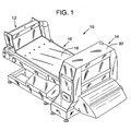
- Figs. 1-3 show an automated bulk optical processing system 10 having an on-belt stabilising system 12 and an off-belt stabilising system 14 for stabilising articles carried by a conveyor 16.
- Processing system 10 preferably performs optical inspection of large quantities of light-weight articles such as, for example, stripped-leaf tobacco or laminae, ground tobacco stems, re-claim, wood chips, or light-weight debris.
- stabilising systems 12 and 14 could be similarly employed by other types of automated processing equipment such as, for example, packaging systems.
- Conveyor 16 includes any commercially available anti-static belt 18. This type of belt reduces any static charge that may develop during operation. Static charge in the belt may cause the articles 17 (Fig.2) to adhere thereto and reduce the effectiveness of the system.
- the belt 18 forms a closed loop around a drive roller 20 and a spaced-apart, free-running end roller 22.
- a motor (not shown) coupled to drive roller 20 drives an upper surface 24 of belt 18 at a velocity in a direction 26 toward the off-belt stabilising system 14 that includes an optical inspection station 28 and a sorting station 30.
- Articles 17 are delivered to belt 18 by an infeed system 46.
- Infeed system 46 is shown as having a curved chute 48 down which articles slide to be accelerated to about the speed of belt 18. The articles slide off a lower end 50 of chute 48 and drop onto belt 18.
- Infeed system 46 could alternatively employ an infeed conveyor belt, inactive chute or a vibrating chute.
- On-belt stabilising system 12 helps to accelerate the articles dropping from chute 48 to the speed of belt 18 by generating a flow 52 of fluid, preferably a readily available gas such as air, that passes between belt 18 and lower end 50 of chute 48.
- Air flow 52 engages the articles as they drop from chute 48 onto belt 18 and functions to accelerate the articles to the velocity of belt 18.
- Air flow 52 has a velocity that may but need not equal the velocity of belt 18. After the articles are accelerated to the velocity of belt 18, air flow 52 functions to stabilise the articles on belt 18.
- the articles dropped onto belt 18 from chute 48 would typically bounce, tumble and roll, thereby requiring a length of belt 18 to allow the articles to settle into moderately stable positions thereon.
- Stabilising system 12 settles the articles onto belt 18 much more quickly, thereby allowing belt 18 to be shortened and processing system 10 to be more compact or allowing conveyor 10 to increase product flow with the same stability and greater throughput of process.
- Stabilising system 12 employs a chamber or plenum 54 that receives air under pressure from a blower 56 via a conduit 57.
- a nozzle 58 in plenum 54 is positioned below and extends across chute 48 and belt 18 to provide a generally smooth flow 52 of air for stabilising the articles.
- Belt 18 carries the articles to the off-belt stabilising system 14 where they are processed.
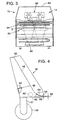
- Fig. 4 is a side view of infeed system 46, which receives the articles at a receiving end 60 of chute 48 from an infeed shaker (not shown). The articles are accelerated by gravity as they slide along chute 48 through a bend 64 toward lower end 50.
- Chamber or plenum 54 is positioned below chute 48 and receives air under pressure from blower 56.
- Bend 64 in chute 48 co-operates with a slanted bottom surface 66 of plenum 54 to form nozzle 58, which extends across the width of belt 18.
- nozzle 58 forms an opening with a height 68 of about 0.25 in. (0.5 cm).
- Ionised air is used to create the flow 52.
- Ionised air is created by passing the air in the plenum 54 across an ion bar 62 mounted in any desired fashion within the plenum 54.
- the ion bar 62 extends across the width of the belt 18 and is of the type known and used by those skilled in the art.
- infeed system 46 Although the specific infeed system 46 is shown and described, it is to be understood that other infeed systems could be used to introduce the light-weight articles onto a conveyor so that they have a velocity substantially the same as the velocity of the belt 18.
- On-belt stabilising system 12 further includes a tunnel 70 that generally encloses upper surface 24 of belt 18 from a tunnel entrance 72.
- Tunnel 70 allows stabilising system 12 to generate a flow 74 of fluid, preferably a readily available gas such as air, that passes over and past the length of belt 18.
- Tunnel 70 is formed by a hood 79 positioned over and extending along belt 18.
- any on-belt stabilising system may be used to stabilise the light-weight articles on the conveyor belt.
- a dual conveyor belt system such as the Tobacco Scan 6000 manufactured by Elbicon located near Brussels, Belgium, may be used that employs a counter-rotating conveyor belt located above the lower article-bearing conveyor belt.
- the counter-rotating conveyor belt creates a flow of air between the lower conveyor belt and the counter-rotating conveyor belt to stabilise the articles on the lower conveyor belt.
- boundary layer In a conventional conveyor system not employing an air assisted stabilising system, only a very thin boundary layer of air travels at or near the speed of the conveyor belt.
- the boundary layer typically extends a few millimetres above the belt.
- Articles with thicknesses greater than a few millimetres extend through the boundary layer to slower or generally stagnant air.
- the articles or certain ones of them can be retarded by the slower-moving air, thereby destabilising the articles on the belt and causing them to roll, tumble, bounce or collide with one another.
- Air flow 64 induces an air draught along tunnel entrance 72 so that the articles carried on belt 18 are gradually stabilised by air flows of increasing velocity.
- Stabilising system 12 stabilises the articles carried on belt 18 so that they are substantially stable and travel at the speed of the belt toward the off-belt stabilising system 14.
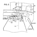
- Off-belt stabilising system 14 includes an end hood portion 80 (Fig. 5) that extends through the inspection station 28 and supports sorting station 30 to provide a closed environment for the articles as they leave belt 18.
- Inspection station 28 includes a housing 82 that encloses a pair of upper and lower lighting units 84 and 86 and upper and lower camera modules 88 and 90 to identify selected optical characteristics of the articles as they pass from belt 18.
- Lighting units 84 and 86 are typically fluorescent tubes mounted within a mounting system (not shown) that may include, for example, tube sockets supported by a light source support connected to housing 82.
- Cameras 88 and 90 view the articles along respective lines of sight 92 and 94 through adjustable mirrors 96 and 98. Inspection station 28 can identify the preselected characteristics of the articles in accordance with the methods and systems described in US-A- 5,085,325.
- upper and lower transparent windows 100 and 102 are mounted within the end hood portion 80.
- the windows may be constructed of any durable transparent material, such as, for example, glass or plastic.
- the upper window 100 may be mounted by brackets 104 and secured by fasteners 106.
- the lower window 102 may be secured by fasteners 107 to flanges 108 and 110 of the end hood portion 80. These windows protect the lighting units 84 and 86 from the articles 17 and from any other debris that may be included within the flow of articles.
- the lighting units 84 and 86 are located substantially close to the articles 17 and the lines of sight 92 and 94 without interfering with the field of view of the cameras 88 and 90.
- the cameras 88 and 90 view the articles along a horizontal scan line S (Fig. 3) extending perpendicular to the direction of travel of the belt 18.
- the scan line has a length substantially the same as the width of the belt 18.
- the light tubes are mounted to extend perpendicularly to the direction of travel of the belt 18 and are, therefore, parallel to the scan line.
- the light tubes cannot be exactly collinear with the scan line because they would block the view of the cameras 88 and 90.
- the light tubes are substantially more collinear with the scan line than has been possible in prior systems. Thus, improved illumination of the articles 17 is provided.
- a sorting station 30 employs multiple "puff jets" X (Fig. 5) positioned across the width of the belt 18 to produce pressurised air directed through an access opening (not shown) in end hood portion 80 to divert selected (typically defective) articles projected along a normal trajectory 112 extending from belt 18.
- the articles may be diverted by sorting station 30 into a defect chute A, thereby allowing acceptable articles to be propelled into an acceptance chute B.
- Air curtain unit 114 having an adjustable nozzle 116 is positioned below end roller 22 and directs an air flow 118 toward normal trajectory 112. Air flow 118 functions to support relatively small or light-weight articles within normal trajectory 112 and prevents the light-weight articles from being drawn around and under roller 22 by turbulent air flow.
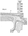
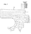
- Figs. 6 and 7 show computer-generated plots of velocities, respectively, of air flow 111 and air flow vectors 113. These plots were generated with finite element analysis software for computational fluid dynamics to represent belt 18 driven at a speed of 15 ft/sec. (4.5 m/sec.).
- the air curtain 114 has a housing 120 (Fig. 5).
- the top 122 of the housing is horizontally adjustable by a rack 124 and pinion 126 which may be rotated either manually or by a motor (not shown). This adjustment varies the nozzle opening 116 through which the air is directed and allows control of the air flow.
- the air flow also acts to clean the lower window 102 of any debris or dust.
- an ion bar 128 similar to ion bar 62 employed within plenum 54 is located within the air curtain 114.
- the air flow from the air curtain is further controlled by a second rack 130 and pinion 132.
- Pinion 132 may be rotated either manually or by a motor (not shown) to selectively or lower a sidewall 134 of the hood 80 to direct to flow of air up toward the articles.
- Air flow 118 formed by air curtain unit 114 offsets the effect of the incidental boundary layer on smaller or lighter-weight articles to improve the sorting accuracy of sorting station 30.
- air flow 118 reduces the amount of dust carried by the boundary layer of flowing air toward lighting units 84 and 86 and along belt 18, thereby improving the cleanliness and efficiency of both the lighting units and the windows.
- processing system 10 processes tobacco leaf products, wood chips, or debris with belt 18 having a width of 2-6 ft (0.6-1.8 m) and driven at a speed of up to 1500 ft/min (7.6 m/sec).
- Stabilising system 12 with nozzle 50 having a height of .25 in. (0.006 m) through which air flow 52 is driven at 10,000 ft/min (50.8 m/sec) displaces about 850 ft 3 /min (24.1 m 3 /min) (standard).
- the articles leave the belt 18 they are completely enclosed within the end hood portion 80 as they are projected past the illumination station 28 and sorter station 30.
- the fact that the articles are enclosed within the end hood portion 80 plus the adjustability of the air flow produced by the air curtain 114 keep the velocity of the articles more uniform. Thus, the articles travel along a more predictable trajectory resulting in a more accurate and efficient processing of the articles.
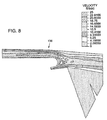
- Figures 8 and 9 are computer-generated plots of velocities 136 and vector paths 138 of air flow within tunnel of off-belt stabilising system 14. These plots were generated with finite element analysis software for computational fluid dynamics to represent belt 18 driven at a speed of up to 17 ft/sec (5.18 m/sec). These conditions represent an exemplary preferred embodiment in which processing system 10 processes tobacco leaf products or wood chips.
- the stabilising system could employ gases other than air as well as fluids other than gases.
Landscapes
- Life Sciences & Earth Sciences (AREA)
- Agronomy & Crop Science (AREA)
- Sorting Of Articles (AREA)
- Manufacturing Of Cigar And Cigarette Tobacco (AREA)
Description
Claims (6)
- A method of processing light-weight articles (17) in an automated bulk processing system (10) that employs an optical inspection and sorting of the articles, comprising the steps of:characterised by enclosing the discharge end by an off-belt end hood portion (80) formed within the off-belt housing (82) to receive the air stream and light-weight articles (17), the enclosing controlling the air stream within the off-belt hood portion (80) to provide a uniform velocity of the articles so that the light-weight articles travel along a controlled flow path.conveying the light-weight articles along a path having an infeed end and a discharge end;providing an air stream (74) that moves along the path with the light-weight articles to stabilise the light-weight articles as they are conveyed along the path from the infeed end to the discharge end;discharging the light-weight articles from the discharge end of the path along the air stream; andprocessing the light-weight articles (17) within an off-belt housing (82) by use of an optical inspection device (28) and a sorting device (30);
- The method of claim 1 and further comprising the step of:providing the optical inspection device (28) with at least one illumination unit (84); andilluminating the articles (17) within the off-belt housing (82) through at least one transparent window located between the illumination unit and the light-weight articles.
- The method of claim 1 or claim 2 further comprising the step of:supporting the sorting device on the hood portion (80) ; andproviding an access opening in the off-belt hood portion (80) to provide communication between the sorting device (30) and an interior of the housing of the off-belt hood portion (80).
- A conveyor system (10), comprising:a conveyor (16) having an infeed end and a discharge end moveable to carry light-weight articles (17) thereon from the infeed end toward the discharge end; anda drive mechanism coupled to the conveyor;a stabiliser device partially enclosing the conveyor to allow a fluid stream (74) to move along the conveyor with the light-weight articles for stabilising the light-weight articles on the conveyor (16) so that the light-weight articles travel at about the same velocity as that of the conveyor as the light-weight articles move from the infeed end to the discharge end, the stabiliser device extending along the conveyor and characterised by an end hood portion (80) extending past and enclosing the discharge end of the conveyor , the end portion (80) being configured to maintain a uniform velocity of the articles and to provide a controlled flow path along which the light-weight articles are projected.
- The system of claim 4 and further comprising an off-belt processor comprising:an optical inspection station (38) for illuminating and viewing the light-weight articles as they travel within the end portion of the stabiliser device; andat least one transparent window (100, 102) in the end hood portion(80)of the stabiliser device and located between the optical inspection station (28) and the light-weight articles through which the light-weight articles are illuminated and viewed by the optical inspection station.
- The system of claim 5, wherein the off-belt processor comprises a sorting station (30) for sorting the light-weight articles within the end hood portion (80) of the stabiliser device.
Applications Claiming Priority (3)
| Application Number | Priority Date | Filing Date | Title |
|---|---|---|---|
| US08/657,357 US6003681A (en) | 1996-06-03 | 1996-06-03 | Off-belt stabilizing system for light-weight articles |
| US657357 | 1996-06-03 | ||
| PCT/US1997/009555 WO1997046328A1 (en) | 1996-06-03 | 1997-06-02 | Off-belt stabilizing system for light-weight articles |
Publications (3)
| Publication Number | Publication Date |
|---|---|
| EP0902732A1 EP0902732A1 (en) | 1999-03-24 |
| EP0902732A4 EP0902732A4 (en) | 2002-10-23 |
| EP0902732B1 true EP0902732B1 (en) | 2005-09-14 |
Family
ID=24636833
Family Applications (1)
| Application Number | Title | Priority Date | Filing Date |
|---|---|---|---|
| EP97928803A Expired - Lifetime EP0902732B1 (en) | 1996-06-03 | 1997-06-02 | Off-belt stabilizing system for light-weight articles |
Country Status (5)
| Country | Link |
|---|---|
| US (1) | US6003681A (en) |
| EP (1) | EP0902732B1 (en) |
| AU (1) | AU3296897A (en) |
| DE (1) | DE69734198T2 (en) |
| WO (1) | WO1997046328A1 (en) |
Cited By (2)
| Publication number | Priority date | Publication date | Assignee | Title |
|---|---|---|---|---|
| EP2684471A1 (en) | 2012-07-11 | 2014-01-15 | HAUNI Maschinenbau AG | Device for separating foreign bodies from a flow of tobacco |
| EP2745714A1 (en) | 2012-12-20 | 2014-06-25 | HAUNI Maschinenbau AG | Foreign body collection device |
Families Citing this family (36)
| Publication number | Priority date | Publication date | Assignee | Title |
|---|---|---|---|---|
| JPH11295439A (en) * | 1998-04-07 | 1999-10-29 | Ishida Co Ltd | Foreign object detector and foreign object detection system |
| US6374998B1 (en) * | 1999-04-29 | 2002-04-23 | Advanced Sorting Technologies Llc | “Acceleration conveyor” |
| FI108920B (en) * | 2000-09-20 | 2002-04-30 | Andritz Oy | A device for separating wood chips into different fractions |
| WO2002076245A1 (en) * | 2001-03-23 | 2002-10-03 | Japan Tobacco Inc. | Shred tobacco feeding apparatus for cigarette wrapping machine |
| US8857621B2 (en) * | 2001-10-02 | 2014-10-14 | Emerging Acquisitions, Llc | De-inking screen with air knife |
| PT1458499E (en) * | 2001-10-02 | 2007-04-30 | Emerging Acquisitions Llc | Screen |
| EP1491478B1 (en) * | 2003-06-25 | 2007-05-09 | Müller Martini Holding AG | Diverting device |
| EP1520488A1 (en) * | 2003-10-02 | 2005-04-06 | Hauni Maschinenbau AG | Device for removing impurities from a tobacco flow |
| US7237680B2 (en) * | 2004-03-01 | 2007-07-03 | Viny Steven M | Air separator and splitter plate system and method of separating garbage |
| CA2499853C (en) * | 2004-03-15 | 2012-11-13 | Universal Leaf Tobacco Company, Inc. | Apparatus and method for scanning and sorting tobacco leaves |
| US7768643B1 (en) * | 2006-03-30 | 2010-08-03 | Key Technology, Inc. | Apparatus and method for classifying and sorting articles |
| US8307987B2 (en) * | 2006-11-03 | 2012-11-13 | Emerging Acquisitions, Llc | Electrostatic material separator |
| US7942273B2 (en) * | 2008-10-07 | 2011-05-17 | Emerging Acquisitions, Llc | Cross flow air separation system |
| US8618432B2 (en) * | 2007-12-18 | 2013-12-31 | Emerging Acquisitions, Llc | Separation system for recyclable material |
| CA2688805C (en) | 2008-11-18 | 2013-07-02 | Jjg Ip Holdings, Llc | Method and apparatus for sorting heterogeneous material |
| DE102009007481A1 (en) | 2009-01-30 | 2010-09-02 | Fraunhofer-Gesellschaft zur Förderung der angewandten Forschung e.V. | Conveyor system for transporting materials, in particular bulk material |
| US8336714B2 (en) | 2009-05-14 | 2012-12-25 | Emerging Acquistions, LLC | Heating system for material processing screen |
| US8281931B2 (en) * | 2009-09-18 | 2012-10-09 | Key Technology, Inc. | Apparatus and method for post-threshing inspection and sorting of tobacco lamina |
| CN101933658B (en) * | 2010-08-27 | 2012-08-15 | 中国烟草总公司郑州烟草研究院 | Sample automatic-blanking and code printing device for cigarette inspection |
| CN101933657B (en) * | 2010-08-27 | 2012-07-25 | 中国烟草总公司郑州烟草研究院 | Automatic and random sample split-charging device for cigarette inspection |
| US9138781B1 (en) * | 2011-02-25 | 2015-09-22 | John Bean Technologies Corporation | Apparatus and method for harvesting portions with fluid nozzle arrays |
| JP5496367B2 (en) * | 2011-12-15 | 2014-05-21 | パナソニック株式会社 | Sorting device, sorting method |
| CN103071629A (en) * | 2013-02-07 | 2013-05-01 | 中国烟草总公司郑州烟草研究院 | Process and device for detecting foreign matters and selecting tobacco leaves before redrying tobacco lamina |
| US9381546B2 (en) * | 2013-04-25 | 2016-07-05 | Panasonic Intellectual Property Management Co., Ltd. | Apparatus and method for separating material |
| DE102014207157A1 (en) * | 2014-02-28 | 2015-09-03 | Fraunhofer-Gesellschaft zur Förderung der angewandten Forschung e.V. | Conveying system, plant for bulk material sorting with such a conveyor system and transport method |
| US20150258577A1 (en) * | 2014-03-17 | 2015-09-17 | Andrew J. Archer | Material Separator |
| JP6283958B2 (en) * | 2015-05-14 | 2018-02-28 | パナソニックIpマネジメント株式会社 | Sorting device |
| DE102018200895A1 (en) * | 2018-01-19 | 2019-07-25 | Fraunhofer-Gesellschaft zur Förderung der angewandten Forschung e.V. | Method and device for determining at least one mechanical property of at least one object |
| CN108311397A (en) * | 2018-02-02 | 2018-07-24 | 李美全 | A kind of laser sorting machine for tobacco edulcoration |
| CN110893399A (en) * | 2018-09-13 | 2020-03-20 | 云南佳叶现代农业发展有限公司 | Intelligent tobacco leaf grading and sorting equipment and method based on visual identification |
| CN113784805A (en) * | 2019-03-05 | 2021-12-10 | Pal有限责任公司 | Waste screening machine and screening method |
| DE102020110976B4 (en) | 2020-04-22 | 2023-12-21 | Separation AG | Optical sorting system for sorting granulate particles |
| CA3208888A1 (en) * | 2021-03-02 | 2022-09-09 | Federico MARQUEZ LOPEZ | Material separation by density |
| CN116967148B (en) * | 2023-08-28 | 2025-12-05 | 洛阳拖拉机研究所有限公司 | A non-destructive testing and grading device for strawberries |
| WO2025068265A1 (en) * | 2023-09-26 | 2025-04-03 | Marel Iceland Ehf. | A food processing apparatus |
| EP4635640A1 (en) * | 2024-04-19 | 2025-10-22 | Okimation Inc. | Pellet sorting method and device, and its pellet flow channel |
Family Cites Families (9)
| Publication number | Priority date | Publication date | Assignee | Title |
|---|---|---|---|---|
| US3097744A (en) * | 1961-02-27 | 1963-07-16 | K & H Equipment Ltd | Quantitative photometric materials sorter |
| US4018674A (en) * | 1972-02-24 | 1977-04-19 | Morris Bennie A | Apparatus for automatically grading leaf tobacco |
| US3928183A (en) * | 1974-03-20 | 1975-12-23 | Emil S Asfour | Tobacco sorting apparatus |
| GB2142426B (en) * | 1983-06-30 | 1986-09-17 | Gunsons Sortex Ltd | Sorting machine and method |
| JPS61162409A (en) * | 1984-12-28 | 1986-07-23 | Toyo Seimaiki Seisakusho:Kk | Flow-down chute of optical selecting device |
| US5048674A (en) * | 1989-12-01 | 1991-09-17 | Simco/Ramic Corporation | Product stabilizer |
| JPH04298273A (en) * | 1991-03-25 | 1992-10-22 | Satake Eng Co Ltd | Color sorter for diced vegetables |
| US5297667A (en) * | 1992-11-12 | 1994-03-29 | Simco/Ramic Corporation | System for stabilizing articles on conveyors |
| US5482166A (en) * | 1994-09-06 | 1996-01-09 | Key Technology, Inc. | Meat trim sorting |
-
1996
- 1996-06-03 US US08/657,357 patent/US6003681A/en not_active Expired - Lifetime
-
1997
- 1997-06-02 EP EP97928803A patent/EP0902732B1/en not_active Expired - Lifetime
- 1997-06-02 DE DE69734198T patent/DE69734198T2/en not_active Expired - Lifetime
- 1997-06-02 AU AU32968/97A patent/AU3296897A/en not_active Abandoned
- 1997-06-02 WO PCT/US1997/009555 patent/WO1997046328A1/en not_active Ceased
Cited By (3)
| Publication number | Priority date | Publication date | Assignee | Title |
|---|---|---|---|---|
| EP2684471A1 (en) | 2012-07-11 | 2014-01-15 | HAUNI Maschinenbau AG | Device for separating foreign bodies from a flow of tobacco |
| EP2745714A1 (en) | 2012-12-20 | 2014-06-25 | HAUNI Maschinenbau AG | Foreign body collection device |
| DE102012224069A1 (en) | 2012-12-20 | 2014-06-26 | Hauni Maschinenbau Ag | Debris collection device |
Also Published As
| Publication number | Publication date |
|---|---|
| US6003681A (en) | 1999-12-21 |
| AU3296897A (en) | 1998-01-05 |
| DE69734198T2 (en) | 2006-06-29 |
| EP0902732A4 (en) | 2002-10-23 |
| EP0902732A1 (en) | 1999-03-24 |
| WO1997046328A1 (en) | 1997-12-11 |
| DE69734198D1 (en) | 2005-10-20 |
Similar Documents
| Publication | Publication Date | Title |
|---|---|---|
| EP0902732B1 (en) | Off-belt stabilizing system for light-weight articles | |
| US5297667A (en) | System for stabilizing articles on conveyors | |
| US6646218B1 (en) | Multi-band spectral sorting system for light-weight articles | |
| US5431289A (en) | Product conveyor | |
| KR0157188B1 (en) | Grain sorting device | |
| CN102481599B (en) | Apparatus and method for post-threshing inspection and sorting of tobacco lamina | |
| US5957306A (en) | Air decelerator for pneumatic sorting system | |
| US6891119B2 (en) | Acceleration conveyor | |
| US20100236994A1 (en) | Sorting apparatus and mehtod utilizing a mechanical diverter | |
| WO2001015822A1 (en) | Foreign matter eliminating device | |
| FI914930A0 (en) | STABILIZATION AND RELEASE OF TRYCKALSTER UNDER DERAS TRANSPORT. | |
| US6056127A (en) | Delivery system for sorting apparatus | |
| EP1838464B1 (en) | Method and apparatus for sorting a gas-driven stream of generally flat and light-weight articles | |
| US4082189A (en) | Apparatus for separating food articles from field debris | |
| JP2002263587A (en) | Waste plastic sorting method and sorting machine | |
| US4736831A (en) | Can unscrambler | |
| US5195628A (en) | Off-loading conveying system | |
| US3002617A (en) | Grading machines | |
| US2776747A (en) | Color sorting machine | |
| JP3016944U (en) | Sorting device for weight sorter | |
| US5893451A (en) | Catenary belt support mechanism | |
| EP0488075A2 (en) | Quality control device particularly for screws, bolts and the like | |
| JPH11179294A (en) | Waste bottle sorting equipment | |
| NL8304371A (en) | Impurity remover for material on conveyor belt - uses video camera to detect passing impurities and control deflector plates across belt | |
| JPH06269742A (en) | Screening and recovering device and method |
Legal Events
| Date | Code | Title | Description |
|---|---|---|---|
| PUAI | Public reference made under article 153(3) epc to a published international application that has entered the european phase |
Free format text: ORIGINAL CODE: 0009012 |
|
| 17P | Request for examination filed |
Effective date: 19981218 |
|
| AK | Designated contracting states |
Kind code of ref document: A1 Designated state(s): BE DE FR GB IT NL |
|
| RAP1 | Party data changed (applicant data changed or rights of an application transferred) |
Owner name: KEY TECHNOLOGY, INC. |
|
| A4 | Supplementary search report drawn up and despatched |
Effective date: 20020905 |
|
| AK | Designated contracting states |
Kind code of ref document: A4 Designated state(s): BE DE FR GB IT NL |
|
| RIC1 | Information provided on ipc code assigned before grant |
Free format text: 7B 07C 5/02 A, 7B 07C 5/342 B |
|
| 17Q | First examination report despatched |
Effective date: 20040527 |
|
| GRAP | Despatch of communication of intention to grant a patent |
Free format text: ORIGINAL CODE: EPIDOSNIGR1 |
|
| GRAS | Grant fee paid |
Free format text: ORIGINAL CODE: EPIDOSNIGR3 |
|
| GRAA | (expected) grant |
Free format text: ORIGINAL CODE: 0009210 |
|
| AK | Designated contracting states |
Kind code of ref document: B1 Designated state(s): BE DE FR GB IT NL |
|
| REG | Reference to a national code |
Ref country code: GB Ref legal event code: FG4D |
|
| REF | Corresponds to: |
Ref document number: 69734198 Country of ref document: DE Date of ref document: 20051020 Kind code of ref document: P |
|
| ET | Fr: translation filed | ||
| PLBE | No opposition filed within time limit |
Free format text: ORIGINAL CODE: 0009261 |
|
| STAA | Information on the status of an ep patent application or granted ep patent |
Free format text: STATUS: NO OPPOSITION FILED WITHIN TIME LIMIT |
|
| 26N | No opposition filed |
Effective date: 20060615 |
|
| PGFP | Annual fee paid to national office [announced via postgrant information from national office to epo] |
Ref country code: IT Payment date: 20080610 Year of fee payment: 12 |
|
| PGFP | Annual fee paid to national office [announced via postgrant information from national office to epo] |
Ref country code: FR Payment date: 20080627 Year of fee payment: 12 |
|
| REG | Reference to a national code |
Ref country code: FR Ref legal event code: ST Effective date: 20100226 |
|
| PG25 | Lapsed in a contracting state [announced via postgrant information from national office to epo] |
Ref country code: FR Free format text: LAPSE BECAUSE OF NON-PAYMENT OF DUE FEES Effective date: 20090630 |
|
| PG25 | Lapsed in a contracting state [announced via postgrant information from national office to epo] |
Ref country code: IT Free format text: LAPSE BECAUSE OF NON-PAYMENT OF DUE FEES Effective date: 20090602 |
|
| PGFP | Annual fee paid to national office [announced via postgrant information from national office to epo] |
Ref country code: GB Payment date: 20150619 Year of fee payment: 19 Ref country code: DE Payment date: 20150619 Year of fee payment: 19 |
|
| PGFP | Annual fee paid to national office [announced via postgrant information from national office to epo] |
Ref country code: BE Payment date: 20150617 Year of fee payment: 19 Ref country code: NL Payment date: 20150617 Year of fee payment: 19 |
|
| PG25 | Lapsed in a contracting state [announced via postgrant information from national office to epo] |
Ref country code: BE Free format text: LAPSE BECAUSE OF NON-PAYMENT OF DUE FEES Effective date: 20160630 |
|
| REG | Reference to a national code |
Ref country code: DE Ref legal event code: R119 Ref document number: 69734198 Country of ref document: DE |
|
| REG | Reference to a national code |
Ref country code: NL Ref legal event code: MM Effective date: 20160701 |
|
| GBPC | Gb: european patent ceased through non-payment of renewal fee |
Effective date: 20160602 |
|
| PG25 | Lapsed in a contracting state [announced via postgrant information from national office to epo] |
Ref country code: DE Free format text: LAPSE BECAUSE OF NON-PAYMENT OF DUE FEES Effective date: 20170103 |
|
| PG25 | Lapsed in a contracting state [announced via postgrant information from national office to epo] |
Ref country code: GB Free format text: LAPSE BECAUSE OF NON-PAYMENT OF DUE FEES Effective date: 20160602 Ref country code: NL Free format text: LAPSE BECAUSE OF NON-PAYMENT OF DUE FEES Effective date: 20160701 |