EP0902709B1 - Stimulateur cardiaque de prevention de l'arrhythmie et de la fibrillation utilisant une stimulation constante - Google Patents
Stimulateur cardiaque de prevention de l'arrhythmie et de la fibrillation utilisant une stimulation constante Download PDFInfo
- Publication number
- EP0902709B1 EP0902709B1 EP97924577A EP97924577A EP0902709B1 EP 0902709 B1 EP0902709 B1 EP 0902709B1 EP 97924577 A EP97924577 A EP 97924577A EP 97924577 A EP97924577 A EP 97924577A EP 0902709 B1 EP0902709 B1 EP 0902709B1
- Authority
- EP
- European Patent Office
- Prior art keywords
- rate
- pacing
- natural
- mode
- detected
- Prior art date
- Legal status (The legal status is an assumption and is not a legal conclusion. Google has not performed a legal analysis and makes no representation as to the accuracy of the status listed.)
- Expired - Lifetime
Links
Images


Classifications
-
- A—HUMAN NECESSITIES
- A61—MEDICAL OR VETERINARY SCIENCE; HYGIENE
- A61N—ELECTROTHERAPY; MAGNETOTHERAPY; RADIATION THERAPY; ULTRASOUND THERAPY
- A61N1/00—Electrotherapy; Circuits therefor
- A61N1/18—Applying electric currents by contact electrodes
- A61N1/32—Applying electric currents by contact electrodes alternating or intermittent currents
- A61N1/36—Applying electric currents by contact electrodes alternating or intermittent currents for stimulation
- A61N1/362—Heart stimulators
- A61N1/3621—Heart stimulators for treating or preventing abnormally high heart rate
- A61N1/3622—Heart stimulators for treating or preventing abnormally high heart rate comprising two or more electrodes co-operating with different heart regions
Definitions
- Pacing literature has pointed out that pacing may be effective in stabilizing otherwise unstable atria, for example "cardiac pacing in special and complex situations" Cardiology Clinics, 10:4 pp. 573-91, 1992 (Barold, SS). See also Br Heart J., 115: page 478, 1988 (Clark M., Sutton R. Ward D. et al.) and "A new pacing algorithm for suppression of atrial fibrillation (Murgatroyd F., et al.) in PACE 17, Part II, page 863.
- the present invention provides an apparatus for controlling a pacing system for delivering pacing pulses to a chamber of a heart comprising: timing control means for controlling the rate of delivery of pacing pulses to said chamber, said timing means capable of at least two modes of adjustment, one of said at least two being a decay mode and the other of said at least two being a ratchet up mode, contraction sense means for detecting cardiac events of said chamber and producing a signal therefrom, and for distinguishing between natural and induced contractions or depolarizations, switching means for signaling said timing control means to change to the ratchet up mode when natural cardiac polarizations of said chamber are detected such that the pacing rate is increased until no further such natural contractions are detected and for a period thereafter maintaining said increased pacing rate, and after said period expires, switching to the decay mode until either a safety pacing rate level is reached or a natural contraction of said chamber is detected, if said safety level is reached, continuing to pace at the safety rate, but if a natural contraction of said chamber
- an apparatus for controlling a heart pacemaker comprising means for pacing at a rate which is just above what usual indications might otherwise suggest is the best pacing rate.
- This has particular application to pacing at just above the sinus rate since one implementation of this invention is designed to eliminate or attenuate the amount of atrial tachycardia and atrial fibrillation.
- Other indications for what the sinus rate should be include sensor rate which is generated by an activity sensor or based on other means such as minute ventilation, etc. It should be recognized that it is contrary to the usual application of this invention to pace above a sensor rate if the sinus rate is less than the sensor rate. In such situations the preferred embodiment simply paces at the sensor rate.
- the "just above the usual rate” is a rate determined by periodically or at predetermined times reducing the pacing rate until a natural rhythm of heart beats is found in the atrium, (i.e., sinus node generated atrial depolarizations) and then increasing the paced rate again by a second predetermined amount.
- This second amount is designed to eliminate the presence of AF and AT (also called Atrial Fibrillation and Atrial Tachycardia).
- the feature provided by this invention can be enabled or disabled. When enabled it will start by decreasing the atrial escape interval on consecutive beats until atrial pacing is established. After a programmable number of beats, the escape interval will be increased incrementally until intrinsic atrial activity is once again discovered. (This is called a "decay" phase.)
- the escape interval When atrial intrinsic depolarizations are sensed, then the escape interval will be again decreased in increments until consistent atrial pacing is restored. (This is called a "capture” or “ratchet up” phase).
- Some additional features include using a lower pulse width and/or amplitude for the pacing pulses during the decay phase than during the capture phase; not using atrial refractory events in atrial interval calculations used for setting the escape interval; and employing the mechanism for preventing long term atrial pacing at a maximum rate to avoid CHF conditions.
- a human body 80 is fitted with an implanted medical device 82, in this example, a hermetically sealed, biocompatable, implanted pulse generator or pacemaker. It is connected to the heart 88 by a lead 84 in the subclavien vein 86 as is a common practice at the current time for implanting pacemaker devices.
- the programmer head 9 with hand operated switches like 8 is preferably connected by a balanced transmission wire system or cable assembly 7 to a "Programmer" or computer that is used to program pulse generators and retains information from them.
- a device as a Programmer 25 may have a keyboard and display means for communication with an attendant (not shown). Such a system is used to communicate telemetrically with the implanted device 82.
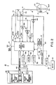
- FIG. 2 is a block circuit diagram illustrating one possible form of a pacemaker 10 capable of carrying out the present invention. A detailed description of its general function follows.
- microprocessor-based architecture it is understood that it could be implemented in other technology such as digital logic-based, custom integrated circuit (IC) architecture, analog circuits, etc., if desired.
- IC integrated circuit
- Lead 14 includes an electrode 24 located near its distal end positioned within the right ventricle 16. Electrode 24 is coupled by a lead conductor 14 through an input capacitor 26 to the node 28, and to the input/output terminals of an input/output circuit 30. Lead 15 has a distal electrode positioned within the right atrium 17. Electrode 22 is coupled by a lead conductor 15 through an input capacitor 75 to a node 76, and to the input/output terminals of the Input/Output circuit 30.
- Circuit 30 contains the operating input and output analog circuits for digital controlling and timing circuits to detect electrical signals derived from the heart, such as the cardiac electrogram (EGM or ECG). It may also receive output from sensors (not shown but which may be connected to the leads 14 and 15 or in the pacemaker body or connector block, etc.), and it is the part which applies stimulating pulses to the heart under the control of software-implemented algorithms in a Microcomputer Circuit 32.
- ECG cardiac electrogram
- sensors not shown but which may be connected to the leads 14 and 15 or in the pacemaker body or connector block, etc.
- Microcomputer Circuit 32 is often configured as an On-Board Circuit 34 and an Off-Board Circuit 36.
- On-Board Circuit 34 includes a microprocessor 38, a system clock 40, and on-board RAM 42 and ROM 44.
- Off-Board Circuit 36 includes an off-board RAM/ROM Unit 46.
- Microcomputer Circuit 32 is coupled by Data Communication Bus 48 to a Digital Controller/Timer Circuit 50.
- Microcomputer Circuit 32 may be fabricated of custom IC devices augmented by standard RAM/ROM components or fabricated in a chip on a hybrid circuit board.
- a battery test circuit 56 will provide information to the controller or the microcomputer directly, in most embodiments through a Vref value circuit like 58 or a suitably configured POR circuit containing end of life indicator or other battery life/power level circuits as are well known in the art.
- An antenna 52 is connected to Input/Output Circuit 30 for purposes of uplink/downlink telemetry through a radio frequency (RF) Transmitter/ Receiver Circuit (RF TX/RX) 54.
- Telemetering both analog and digital data between antenna 52 and an external device, such as an external "Programmer” is accomplished in preferred embodiments by means such as are described in U.S. Pat. No. 5,127,404, "Telemetry Format for Implantable Medical Device".
- a reed switch 51 is connected to Input/Output Circuit 30 to enable patient follow-up by disabling sense amplifier 64 and enabling telemetry and programming functions, as is known in the art. Commonly a reed switch needs to be closed to telemeter out data but some devices will not contain reed switches, preferring to use other known devices or methods acceptable to guarantee reliability of telemetry data or initiation and against inappropriate usage.
- a Crystal Oscillator Circuit 57 is preferred for providing the main timing clock signals to Digital Controller Timer Circuit 50. Most timing periods depend on a clock to turn on or off under program control, and the length of timing is generally established with reference to a number of clock cycles.
- a Vref/Bias Circuit 58 generates a stable voltage reference and bias currents for the analog circuits of Input/Output Circuit 30.
- An ADC/ Multiplexer Circuit (ADC/MUX) 60 digitizes analog signals and voltages to provide telemetry and a replacement time-indicating or end-of-life function (EOL).
- a Power-on-Reset Circuit (POR) 62 functions to initialize the pacemaker 10 with programmed values during power-up, and reset the program values to default states upon the detection of a low battery condition or transiently in the presence of certain undesirable conditions such as unacceptably high electromagnetic or electrical interference (EMI), for example.
- EMI electromagnetic or electrical interference
- the operating commands for controlling the timing of the pacemaker depicted in Figure 2 are coupled by bus 48 to Digital Controller/Timer Circuit 50 wherein digital timers set the overall escape interval of the pacemaker and may have separate atrial and ventricular escape intervals, as well as various refractory (PVARP), blanking (PVAB) and other timing windows for controlling the operation of the peripheral components within Input/Output Circuit 50.
- digital timers set the overall escape interval of the pacemaker and may have separate atrial and ventricular escape intervals, as well as various refractory (PVARP), blanking (PVAB) and other timing windows for controlling the operation of the peripheral components within Input/Output Circuit 50.
- PVARP refractory
- PVAB blanking
- other timing windows for controlling the operation of the peripheral components within Input/Output Circuit 50.
- these may also include atrial interval values, AV intervals, and so forth.
- Digital Controller/Timer Circuit 50 is coupled to sense amplifiers (SENSE) 64 and 67, and to electrogram (EGM) amplifiers 66 and 73 for receiving amplified and processed signals picked up from electrode 24 through lead 14 and capacitor 26, and for receiving amplified and processed signals picked up from electrode 22 through lead 15 and capacitor 75, representative of the electrical activity of the patient's ventricle 16 and atrium 17, respectively.
- SENSE amplifiers 64 and 67 produce sense event signals for re-setting the escape interval timer within Circuit 50.
- the electrogram signal developed by EGM amplifier 66 is used in those occasions when the implanted device is being interrogated by the external programmer/transceiver (not shown) in order to transmit by uplink telemetry a representation of the analog electrogram of the patient's electrical heart activity as described in U.S. Pat. No. 4,556,063, issued to Thompson et al., entitled "Telemetry System for a Medical Device".
- Output pulse generators 68 and 71 provide the pacing stimuli to the patient's heart 11 through output capacitors 74 and 77 and leads 14 and 15 in response to paced trigger signals developed by Digital Controller/Timer Circuit 50 each time the escape interval times out, or an externally transmitted pacing command has been received, or in response to other stored commands as is well known in the pacing art.
- pacemaker 10 is capable of operating in various non-rate-responsive modes which include DDD, DDI, VVI, VOO and VVT, as well as corresponding rate-responsive modes of DDDR, DDIR, VVIR, VOOR and VVTR as well as the A (atrial) analogs of these: AAI/R, AAT/R, AOO/R, et cetera.
- pacemaker 10 can be programmably configured to operate such that it varies its rate only in response to one selected sensor output, or in response to both sensor outputs, if desired. Many other features and functions of pacemakers may be incorporated without going beyond the scope of this invention.
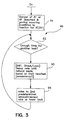
- Step 91 also checks to see that atrial pacing is enabled. A timer or flag is checked to see if enough time has gone by (as monitored with reference to the clock circuit of Fig. 2) in step 92 to decrease the atrial pacing rate in order to determine whether there was a natural sinus rhythm "just under" that pacing rate. In step 92, the rate is iteratively reduced (decayed) until a natural beat is sensed or a lower limit is reached.
- the algorithm can take one of several turns within step 93 such that it may either check for a natural sinus rate to determine what that is and boost the rate of pacing a conveniently safe amount above that or it can ratchet the rate upward until no naturally conductive beats are found. If the later branch is taken, a certain number of atrial paces in a row without natural conduction or premature natural conduction must occur for the algorithm to assume that an appropriate pacing rate has been reached.
- Fig. 5 in which paired flowcharts 50a and 50b are illustrated, the beat by beat functioning of an algorithm in accord with a preferred embodiment of this invention is described. If we begin with an atrial pace (51a) then we start with the question, "are we already in a decay state (52a)?", which the program will determine by looking at the memory for this indicator, and if so, then we will increment the decay counter in step 56.
- counters which each are valued at one 8 millisecond increment can be used to both hold the number of decay increments to apply to the pacing pulse timing and to be incremented in accord with the flow chart. Separate counters could be used if desired, and numerous counting methods are readily available to those of ordinary skill.
- the escape interval in this case of our preferred embodiment will be incremented by eight milliseconds (one increment) when the counter exceeds four, at which time the counter will be reset. (See Fig. 4b-48).
- the algorithm will then move on to step 57.
- step 56 because we are in a "decay" state, in one form of the embodiment the atrial outputs (pulse width, pulse amplitude for stimulation) may also be lowered. (It is known to use autocapture testing algorithms to set the pulse width and duration based on whether pacing is being accomplished at a given level of stimulus, and even to optimize such parameters.
- the energy value of the pacing pulse can be lowered without losing the pacing rate.
- This algorithm can take advantage of an autocapture feature in a pacemaker if desired to ensure that lowering the energy value (pulse width/amplitude) of the pacing stimulus will not result in loss of capture.
- the preferred program asks whether or not the program is in the "delay" state at step 53. If the program is (yes) in this delay state, the algorithm moves to step 55, the delay counter is incremented and "state” is changed to "decay” when the counter exceeds a maximum number of delay beats which we set in the preferred embodiment at 12. This is illustrated in Fig. 4b at 47. Delay operates to provide for a plateaued pacing rate to prevent too rapid switching between decay and "ratchet" or "rise” phases of this program.
- step 54, 55, and 56 the next step is a determination of the answer to the question is the mechanism pacing within 80 milliseconds of the maximum pace rate (step 57) and if so, (step 58) are there too many consecutive atrial paces too near the maximum pacing rate, and if so, the algorithm moves on to step 65.
- step 55 we decay to an interim rate (43 of Fig. 4a) to wait for intrinsic activity below an intermediate rate and the program then exits that step 53a(1).
- step 57 we find that pacing is not within 80 milliseconds of the maximum pacing rate then we reset a variable called "high rate pace count" at step 59 and again proceed to exit at step 53a(2). (The rise state here is similar to the ratchet state described with reference to Fig. 6.)
- step 51b we move to decrease the escape interval by 40 milliseconds (five basic increments) at 52b and increase the atrial output (pulse width/pulse amplitude) and further change the state of the operation to rise. After this we exit at step 53b.
- Flag A indicates that this algorithm in step 13 works with another to determine whether or not the tachy mode switch or other tachy indicator is on in the pacemaker.
- Flag B describes the program's arm with elements 81-76 which is that segment of the algorithm that provides return to "ratchet" operation.
- Flag C indicates the area of the algorithm in which the ratcheting back up of the pacing rate occurs upon detection of intrinsic sinus activity.
- Flag E indicates the segment of the algorithm which is the decay arm, and Flag F indicates the segment used for a check against sustained high rate pacing.
- the program 60 starts at input 3.
- This program can be triggered by automatic diagnostics that are known in the art to suggest the presence of or detect atrial arrhythmias, mode smoothing programs or hysteresis type programs used for automatic responses to sensed atrial arrhythmias, successful arrhythmia termination sequences and so on.
- step 13 If there is atrial tachycardia present, the algorithm exits at 4a from step 13. If there is not, the algorithm moves to step 19 where it checks its current state. If during initiation a state is not yet set, the program moves to "Ratchet" state.
- the last atrial sense will be checked to determine whether it was an atrial pace in block 31 or an atrial refractory sense in block 37. If it is an atrial pace, the increment pace counter, step 33, is taken and a counter value is increased by one and step 35 is next taken.
- the output of the atrial pulse can be decreased at this step 35 in the preferred embodiment since the atrium is assumed to be entrained. Typical values for entrained atria are around 2V, 0.5ms compared to typical ratchet values of near 5V, 0.5ms pulse amplitude, duration.
- step 81 the first thing the algorithm does is to wait in step 81 for the next atrial sense or paced event. If it is an atrial pace event, then the algorithm moves to step 6 and increments the slow beat counter. If it is a sensed event, then the Pwave to Pwave (P-P) interval is checked to see if it is larger than the resynchronization interval.
- P-P Pwave to Pwave
- the program moves into the decay phase, it is because of a consistently high sinus rate, causing the program to ratchet up in rate.
- the escape interval is increased on each beat (lowering the rate).
- the occurrence of atrial pacing means the sinus rate is slower than the rate at which the pacemaker wants to pace (be it sensor rate or some other rate, say a minimum maintenance rate for example).
- the resynchronization interval is 80ms (in a preferred embodiment) below the maximum rate (41, Fig. 4a).
- step 72 of the program 60 determines by looking at the pace counters set incremented in step 33 whether the pace counter equals the plateau count. If it does, the pace counter is reset to zero and the escape interval is increased by the INC. DELTA amount.
- step 78 the escape interval is set equal to the maximum of the escape interval (its own value) or the lower rate or the sensor rate. If the pace counter however in step 72 is determined to be not equal to the plateau count, then the changes in pace counter and escape interval of step 76 and 78 are not made and the program moves to step 105.
- step 31 If in step 31 the last atrial event was not an atrial pace, a determination must next be made whether it is an atrial refractory sense (that way it would be an indication that there is ectopy) or in other words that an AT event has occurred. This would also be termed a Premature Atrial Contraction or PAC. If there is no atrial refractory sense (PAC) in step 37 and it had not been an atrial pace in step 31, then the pace counter is reset to zero (step 101), the escape interval is decreased in step 102, and the atrial output voltage and or pulse width is set to overdrive value in step 103. The escape interval is then set equal to the minimum of the escape interval or the minimum pace interval in step 104. The sections flagged as C and E thus maintain pacing just above the sinus rate, provided no ectopic beats are found.
- PAC Premature Atrial Contraction
- step 105 a determination is made of whether or not the escape interval is still producing a rate faster than the high rate cut off over the extended period. If not, then the high rate count is set equal to zero and the ratchet arm of this program is exited at 4C. If the escape interval is higher than the high rate cut off value (80ms below the maximum rate in the preferred embodiment), the high rate count counter is incremented in step 107 and the high rate count thus incremented is checked in step 108 to determine whether it is now greater than the maximum high rate count level. If it is not, again the program proceeds to exit 4C.
- the high rate count counter is incremented in step 107 and the high rate count thus incremented is checked in step 108 to determine whether it is now greater than the maximum high rate count level. If it is not, again the program proceeds to exit 4C.
- step 109 If the high rate count is greater than the maximum high rate allowed in step 108, the preferred embodiment program checks in step 109 whether the sensor interval is still producing a rate faster than the maximum sensor rate. If it is, the high rate count is set back to zero and exit 4C is again taken. We assume in this case the high sinus rate is an appropriate response to exercise. If it is not, however, the state is set to decay and the mode is set for the pacemaker to DDD in step 112. Then the program exits at 4C. If the state has been set to decay on the next go through of flow chart 60 at step 19 the decay branch is taken and it is determined whether or not the last atrial event was an atrial pace in step 81. If it was, the slow beat count is incremented by one.
- the resume count means that enough beats have occurred at a rate below the resynchronization interval and it is time to reinitialize and restart the algorithm.
- a larger resume count means there will be less reinitialization starts of the program and a smaller resume count value means the program initiation will be more sensitive.
- the mode is set to DDI, the state is changed to ratchet, the slow beat count is reset to zero and the total beat count is set to zero in step 76 before the program exits at 4B.
- the first decay atrial event is determined at step 81 not to be an atrial pace, a check is made to see if the P wave to P wave interval is greater than the resynchronization interval in step 83.
- the resynchronization interval is equivalent to the intermediate rate 43 of Figure 4a which is 80 milliseconds lower than the maximum rate 41. It is also higher than the interim rate 42.
- the total beats count is kept to prevent high atrial (sinus) rates from thwarting the intent of the program. In other words, a high normal sinus would otherwise disable the program altogether, never allowing the pacer to pace at a rate above the high sinus rate.
- step 85 the total beats count is checked to see if it is greater than the maximum number of decay beats allowed and if it is not, then the total beats count is incremented at step 87 and at step 89 the escape interval is increased by INC DELTA.
- the escape interval is set equal to the maximum of the lower rate and the sensor rate. Basically then, we are looking for either atrial paces (81) which means slow heart rate, or P-P intervals below the Intermediate or Resynchronization rate. When we find them and they add up to a large enough count, we shift to ratchet or rise phase. The program then exits at step 4b.
- An additional element that could be employed in adopting direct consistent ventricular pacing would be its application by timing based on decreasing the AV interval rather than basing the timing exclusively on same chamber events, P-P intervals or the like as is described with respect to consistent atrial pacing.
- atrial algorithms application of such AV interval timing for ventricular pulse triggering for a ventricular algorithm is within the ordinary skill of those in this art such that the description in this paragraph is sufficient to apply it to a reader's preferred pacemaker.
- the ventricle For conduction block, the ventricle should be paced with a decay mode and a ratchet mode as described above for atrial pacing, but applied to the ventricular pacing control. If there is a ventricular sense, then the control should be passed to the ratchet up part of the inventive algorithm. The ventricular pacing should be maintained until a ventricular sensed event is found, which would indicate an aberrant ventricular action, like a PVC (premature ventricular contraction), suggesting abnormal conduction to the ventricle.
- a ventricular sensed event like a PVC (premature ventricular contraction)
- pacing in both the atrium and ventricle should be made available using both the ratchet and decay parts of the algorithms.
- the program should be in the ratchet up phase for the atrial rate, driving the ventricular rate up through the consistent atrial pacing.
- the second option is to ratchet up the atrial rate using the ratchet algorithm and shortening the AV interval to increase the Ventricular rate and ensure paced ventricular contractions. This second option could be used for conduction block patients as well but will obviously require substantially more expenditure of battery power to supply the ventricular pacing.
Landscapes
- Health & Medical Sciences (AREA)
- Cardiology (AREA)
- Heart & Thoracic Surgery (AREA)
- Engineering & Computer Science (AREA)
- Biomedical Technology (AREA)
- Nuclear Medicine, Radiotherapy & Molecular Imaging (AREA)
- Radiology & Medical Imaging (AREA)
- Life Sciences & Earth Sciences (AREA)
- Animal Behavior & Ethology (AREA)
- General Health & Medical Sciences (AREA)
- Public Health (AREA)
- Veterinary Medicine (AREA)
- Electrotherapy Devices (AREA)
- Measurement And Recording Of Electrical Phenomena And Electrical Characteristics Of The Living Body (AREA)
Claims (12)
- Dispositif pour commander un système de stimulation cardiaque pour délivrer des impulsions de stimulation à une chambre cardiaque, comprenant :des moyens de commande de synchronisation (50) pour commander le rythme de fourniture des impulsions de stimulation à ladite chambre, lesdits moyens de synchronisation étant capables d'au moins deux modes de réglage, l'un des au moins deux étant un mode de décroissance et l'autre des au moins deux étant un mode de croissance,des moyens de détection de contraction (64, 67) pour détecter des événements cardiaques de ladite chambre, et pour produire un signal, et pour distinguer entre les contractions naturelles et induites ou les dépolarisations,des moyens de commutation (32) pour indiquer auxdits moyens de commande de synchronisation de passer en mode de croissance quand des dépolarisations cardiaques naturelles de ladite chambre sont détectées de telle sorte que le rythme de stimulation est augmenté jusqu'à ce qu'aucune autre telle contraction naturelle ne soit détectée, et de maintenir ensuite pendant une période le rythme de stimulation accru, et une fois que ladite période a expiré, de passer en mode de décroissance jusqu'à ce qu'un niveau de rythme de stimulation de sécurité soit atteint ou qu'une contraction naturelle de ladite chambre soit détectée, si ledit niveau de sécurité est atteint, de continuer à stimuler au rythme de sécurité, mais si une contraction naturelle de ladite chambre est détecté avant d'atteindre le rythme de sécurité dans ledit mode de décroissance, alors indiquer auxdits moyens de commande de synchronisation de stimuler à un rythme plus grand d'un incrément qu'un rythme auquel la dépolarisation ou la contraction naturelle a été trouvée.
- Dispositif selon la revendication 1, dans lequel au cours du mode de croissance, l'amplitude et / ou la largeur de l'impulsion des impulsions de stimulation est augmentée pour assurer la capture de la chambre.
- Dispositif selon l'une quelconque des revendications 1 ou 2, dans lequel au cours du mode de décroissance, le niveau de l'impulsion de stimulation fournie, est abaissé pour conserver la puissance en réduisant l'amplitude et / ou la largeur de l'impulsion.
- Dispositif selon l'une quelconque des revendications 1, 2 ou 3, dans lequel un utilisateur peut fixer le niveau de l'amplitude et / ou de la largeur de l'impulsion de stimulation.
- Dispositif selon l'une quelconque des revendications précédentes, comprenant de plus un processeur de détection de capture (34) ayant un algorithme pour déterminer et fixer l'amplitude et / ou la largeur de l'impulsion des impulsions de stimulation fournies automatiquement, et comprenant de plus des moyens pour abaisser l'amplitude et / ou la largeur de l'impulsion au cours du mode de décroissance à partir dudit niveau déterminé pour conserver la puissance de fonctionnement au cours du mode de décroissance.
- Dispositif selon l'une quelconque des revendications précédentes, dans lequel ledit mode de décroissance est construit pour se terminer quand un sinus lent est détecté ou quand une période de décroissance maximum prédéterminée totale s'est écoulée, quel que soit ce qui se produit en premier.
- Dispositif selon la revendication 6, dans lequel ledit sinus lent est détecté quand le rythme cardiaque n'excède pas un rythme de resynchronisation prédéterminé.
- Dispositif selon l'une quelconque des revendications précédentes, pour commander un système de stimulation pour délivrer des impulsions de stimulation à une oreillette cardiaque.
- Dispositif selon l'une quelconque des revendications précédentes, pour commander le système de stimulation pour délivrer des impulsions de stimulation à un ventricule cardiaque.
- Dispsoitif selon l'une quelconque des revendications précédentes pour commander un système de stimulation pour délivrer des impulsions de stimulation à une oreillette ou à un ventricule cardiaque, dans lequel :lesdits moyens de commande de synchronisation (50) commandent le rythme de fourniture desdites impulsions de stimulation à ladite oreillette ;lesdits moyens de détection de contraction (64) détectent des événements ventriculaires, et distinguent entre les contractions induites et les contractions induites non stimulées naturelles, et des dépolarisations d'un ventricule ; etlesdits moyens de commutation (32) indiquent auxdits moyens de commande de synchronisation de passer dans un mode de croissance quand des dépolarisations ventriculaires naturelles sont détectées de telle sorte que le rythme de stimulation est augmenté jusqu'à ce qu'aucune autre telle contraction ventriculaire naturelle ne soit détectée, et de maintenir ensuite pendant une période le rythme de stimulation accru, et une fois que ladite période a expiré, de passer en mode de décroissance jusqu'à ce qu'un niveau de rythme de stimulation de sécurité soit atteint ou qu'une contraction ventriculaire naturelle soit détectée, si ledit niveau de sécurité est atteint, de continuer à stimuler au rythme de sécurité, mais si une contraction ventriculaire naturelle est détectée avant d'atteindre le rythme de sécurité dans ledit mode de décroissance, alors d'indiquer auxdits moyens de commande de synchronisation de stimuler à un rythme plus grand d'un incrément qu'un rythme auquel la dépolarisation ou une contraction ventriculaire induite non stimulée naturelle ait été trouvée.
- Dispositif selon la revendication 10, dans lequel, au cours du mode de décroissance, lesdits moyens de commutation envoient un signal auxdits moyens de commande pour rallonger l'intervalle AV.
- Dispositif selon l'une quelconque des revendications 10 ou 11, dans lequel au cours du mode de croissance, lesdits moyens de commutation envoient un signal auxdits moyens de commande pour raccourcir l'intervalle AV.
Applications Claiming Priority (3)
| Application Number | Priority Date | Filing Date | Title |
|---|---|---|---|
| US08/642,717 US5713929A (en) | 1996-05-03 | 1996-05-03 | Arrhythmia and fibrillation prevention pacemaker using ratchet up and decay modes of operation |
| PCT/US1997/007537 WO1997041922A1 (fr) | 1996-05-03 | 1997-05-05 | Stimulateur cardiaque de prevention de l'arrhythmie et de la fibrillation utilisant une stimulation constante |
| US642717 | 2000-08-21 |
Publications (2)
| Publication Number | Publication Date |
|---|---|
| EP0902709A1 EP0902709A1 (fr) | 1999-03-24 |
| EP0902709B1 true EP0902709B1 (fr) | 2003-09-17 |
Family
ID=24577712
Family Applications (1)
| Application Number | Title | Priority Date | Filing Date |
|---|---|---|---|
| EP97924577A Expired - Lifetime EP0902709B1 (fr) | 1996-05-03 | 1997-05-05 | Stimulateur cardiaque de prevention de l'arrhythmie et de la fibrillation utilisant une stimulation constante |
Country Status (7)
| Country | Link |
|---|---|
| US (1) | US5713929A (fr) |
| EP (1) | EP0902709B1 (fr) |
| JP (1) | JP2000510010A (fr) |
| AU (1) | AU720675B2 (fr) |
| CA (1) | CA2250198C (fr) |
| DE (1) | DE69724952T2 (fr) |
| WO (1) | WO1997041922A1 (fr) |
Families Citing this family (110)
| Publication number | Priority date | Publication date | Assignee | Title |
|---|---|---|---|---|
| US6136019A (en) * | 1996-08-19 | 2000-10-24 | Mower Family Chf Treatment Irrevocable Trust | Augmentation of electrical conduction and contractility by biphasic cardiac pacing administered via the cardiac blood pool |
| US6343232B1 (en) | 1966-08-19 | 2002-01-29 | Mower Chf Treatment Irrevocable Trust | Augmentation of muscle contractility by biphasic stimulation |
| US6141587A (en) * | 1996-08-19 | 2000-10-31 | Mower Family Chf Treatment Irrevocable Trust | Augmentation of muscle contractility by biphasic stimulation |
| US8825152B2 (en) * | 1996-01-08 | 2014-09-02 | Impulse Dynamics, N.V. | Modulation of intracellular calcium concentration using non-excitatory electrical signals applied to the tissue |
| JP4175662B2 (ja) | 1996-01-08 | 2008-11-05 | インパルス ダイナミクス エヌ.ヴイ. | 電気的筋肉制御装置 |
| US9289618B1 (en) | 1996-01-08 | 2016-03-22 | Impulse Dynamics Nv | Electrical muscle controller |
| US7167748B2 (en) | 1996-01-08 | 2007-01-23 | Impulse Dynamics Nv | Electrical muscle controller |
| US8321013B2 (en) * | 1996-01-08 | 2012-11-27 | Impulse Dynamics, N.V. | Electrical muscle controller and pacing with hemodynamic enhancement |
| US9713723B2 (en) | 1996-01-11 | 2017-07-25 | Impulse Dynamics Nv | Signal delivery through the right ventricular septum |
| US7225019B2 (en) | 1996-04-30 | 2007-05-29 | Medtronic, Inc. | Method and system for nerve stimulation and cardiac sensing prior to and during a medical procedure |
| US6628987B1 (en) * | 2000-09-26 | 2003-09-30 | Medtronic, Inc. | Method and system for sensing cardiac contractions during vagal stimulation-induced cardiopalegia |
| US20040199209A1 (en) * | 2003-04-07 | 2004-10-07 | Hill Michael R.S. | Method and system for delivery of vasoactive drugs to the heart prior to and during a medical procedure |
| US8036741B2 (en) | 1996-04-30 | 2011-10-11 | Medtronic, Inc. | Method and system for nerve stimulation and cardiac sensing prior to and during a medical procedure |
| US7269457B2 (en) * | 1996-04-30 | 2007-09-11 | Medtronic, Inc. | Method and system for vagal nerve stimulation with multi-site cardiac pacing |
| US6449507B1 (en) * | 1996-04-30 | 2002-09-10 | Medtronic, Inc. | Method and system for nerve stimulation prior to and during a medical procedure |
| US6904318B2 (en) * | 2000-09-26 | 2005-06-07 | Medtronic, Inc. | Method and system for monitoring and controlling systemic and pulmonary circulation during a medical procedure |
| US6263244B1 (en) | 1996-05-14 | 2001-07-17 | Pacesetter, Inc. | Implantable stimulation device and method for determining atrial autocapture using PVC response |
| US7440800B2 (en) * | 1996-08-19 | 2008-10-21 | Mr3 Medical, Llc | System and method for managing detrimental cardiac remodeling |
| US7203537B2 (en) | 1996-08-19 | 2007-04-10 | Mr3 Medical, Llc | System and method for breaking reentry circuits by cooling cardiac tissue |
| US6341235B1 (en) | 1996-08-19 | 2002-01-22 | Mower Chf Treatment Irrevocable Trust | Augmentation of electrical conduction and contractility by biphasic cardiac pacing administered via the cardiac blood pool |
| US7908003B1 (en) | 1996-08-19 | 2011-03-15 | Mr3 Medical Llc | System and method for treating ischemia by improving cardiac efficiency |
| US8447399B2 (en) * | 1996-08-19 | 2013-05-21 | Mr3 Medical, Llc | System and method for managing detrimental cardiac remodeling |
| US6178351B1 (en) | 1996-08-19 | 2001-01-23 | The Mower Family Chf Treatment Irrevocable Trust | Atrial sensing and multiple site stimulation as intervention means for atrial fibrillation |
| US6337995B1 (en) | 1996-08-19 | 2002-01-08 | Mower Chf Treatment Irrevocable Trust | Atrial sensing and multiple site stimulation as intervention for atrial fibrillation |
| US7840264B1 (en) | 1996-08-19 | 2010-11-23 | Mr3 Medical, Llc | System and method for breaking reentry circuits by cooling cardiac tissue |
| US6411847B1 (en) | 1996-08-19 | 2002-06-25 | Morton M. Mower | Apparatus for applying cyclic pacing at an average rate just above the intrinsic heart rate |
| US6295470B1 (en) * | 1996-08-19 | 2001-09-25 | The Mower Family Chf Treatment Irrevocable Trust | Antitachycardial pacing |
| US6141586A (en) * | 1996-08-19 | 2000-10-31 | Mower Family Chf Treatment Irrevocable Trust | Method and apparatus to allow cyclic pacing at an average rate just above the intrinsic heart rate so as to maximize inotropic pacing effects at minimal heart rates |
| FR2763247B1 (fr) * | 1997-05-16 | 2000-02-18 | Ela Medical Sa | Dispositif medical implantable actif, notamment stimulateur cardiaque, defibrillateur et/ou cardioverteur a reduction des episodes d'arythmie, notamment d'arythmie auriculaire |
| US6479523B1 (en) | 1997-08-26 | 2002-11-12 | Emory University | Pharmacologic drug combination in vagal-induced asystole |
| US6067470A (en) * | 1998-03-05 | 2000-05-23 | Mower Family Chf Treatment Irrevocable Trust | System and method for multiple site biphasic stimulation to revert ventricular arrhythmias |
| US5978709A (en) * | 1998-06-16 | 1999-11-02 | Vitatron Medical, B.V. | Pacemaker system with improved techniques for preventing and suppressing atrial arrhythmias |
| DE69925493T2 (de) | 1998-08-17 | 2006-01-26 | Medtronic, Inc., Minneapolis | Vorrichtung zur vorbeugung von vorhofstachyarrhythmien |
| WO2000038782A1 (fr) | 1998-12-28 | 2000-07-06 | Medtronic, Inc. | Regularisation de la frequence ventriculaire lors de tachyarythmie auriculaire |
| US6411845B1 (en) | 1999-03-04 | 2002-06-25 | Mower Chf Treatment Irrevocable Trust | System for multiple site biphasic stimulation to revert ventricular arrhythmias |
| US8700161B2 (en) * | 1999-03-05 | 2014-04-15 | Metacure Limited | Blood glucose level control |
| US9101765B2 (en) * | 1999-03-05 | 2015-08-11 | Metacure Limited | Non-immediate effects of therapy |
| US8019421B2 (en) * | 1999-03-05 | 2011-09-13 | Metacure Limited | Blood glucose level control |
| US20040249421A1 (en) * | 2000-09-13 | 2004-12-09 | Impulse Dynamics Nv | Blood glucose level control |
| US8666495B2 (en) * | 1999-03-05 | 2014-03-04 | Metacure Limited | Gastrointestinal methods and apparatus for use in treating disorders and controlling blood sugar |
| US6285907B1 (en) | 1999-05-21 | 2001-09-04 | Cardiac Pacemakers, Inc. | System providing ventricular pacing and biventricular coordination |
| US7212860B2 (en) * | 1999-05-21 | 2007-05-01 | Cardiac Pacemakers, Inc. | Apparatus and method for pacing mode switching during atrial tachyarrhythmias |
| US6351669B1 (en) | 1999-05-21 | 2002-02-26 | Cardiac Pacemakers, Inc. | Cardiac rhythm management system promoting atrial pacing |
| US7181278B2 (en) | 1999-05-21 | 2007-02-20 | Cardiac Pacemakers, Inc. | Apparatus and method for ventricular rate regularization |
| US8064997B2 (en) * | 1999-05-21 | 2011-11-22 | Cardiac Pacemakers, Inc. | Method and apparatus for treating irregular ventricular contractions such as during atrial arrhythmia |
| US7062325B1 (en) * | 1999-05-21 | 2006-06-13 | Cardiac Pacemakers Inc | Method and apparatus for treating irregular ventricular contractions such as during atrial arrhythmia |
| US7142918B2 (en) * | 2000-12-26 | 2006-11-28 | Cardiac Pacemakers, Inc. | Apparatus and method for pacing mode switching during atrial tachyarrhythmias |
| US6430438B1 (en) | 1999-05-21 | 2002-08-06 | Cardiac Pacemakers, Inc. | Cardiac rhythm management system with atrial shock timing optimization |
| US6501988B2 (en) | 2000-12-26 | 2002-12-31 | Cardiac Pacemakers Inc. | Apparatus and method for ventricular rate regularization with biventricular sensing |
| AU4776000A (en) * | 1999-05-26 | 2000-12-18 | Impulse Dynamic Nv | Shockless defibrillation |
| US6442429B1 (en) | 1999-06-18 | 2002-08-27 | Medtronic, Inc. | Method and apparatus for diagnosis and treatment of arrhythmias |
| CA2376903A1 (fr) * | 1999-06-25 | 2001-01-04 | Emory University | Dispositifs et methodes de stimulation du nerf vague |
| US6324422B1 (en) * | 1999-11-17 | 2001-11-27 | Pacesetter, Inc. | Methods for sensing arrhythmias in a pacemaker/defibrillator and a pacemaker/defibrillator programmed to implement the same |
| US6519493B1 (en) | 1999-12-23 | 2003-02-11 | Pacesetter, Inc. | Methods and apparatus for overdrive pacing heart tissue using an implantable cardiac stimulation device |
| US6510342B1 (en) | 2000-04-12 | 2003-01-21 | Pacesetter, Inc. | Methods and apparatus for preventing atrial arrhythmias by overdrive pacing multiple heart tissue sites using an implantable cardiac stimulation device |
| US6606517B1 (en) * | 2000-04-12 | 2003-08-12 | Pacesetter, Inc. | Methods and apparatus for preventing atrial arrhythmias by overdrive pacing and prolonging atrial refractoriness using an implantable cardiac stimulation device |
| US6501987B1 (en) * | 2000-05-26 | 2002-12-31 | Cardiac Pacemakers, Inc. | Rate smoothing control |
| US7039461B1 (en) * | 2000-05-13 | 2006-05-02 | Cardiac Pacemakers, Inc. | Cardiac pacing system for prevention of ventricular fibrillation and ventricular tachycardia episode |
| US7239914B2 (en) | 2000-05-13 | 2007-07-03 | Cardiac Pacemakers, Inc. | Rate smoothing control |
| US6522925B1 (en) * | 2000-05-13 | 2003-02-18 | Cardiac Pacemakers, Inc. | System and method for detection enhancement programming |
| US8512220B2 (en) * | 2000-05-26 | 2013-08-20 | Cardiac Pacemakers, Inc. | Rate smoothing control |
| US6424865B1 (en) | 2000-07-13 | 2002-07-23 | Cardiac Pacemakers, Inc. | Ventricular conduction delay trending system and method |
| US6829504B1 (en) * | 2000-09-14 | 2004-12-07 | Cardiac Pacemakers, Inc. | System and method for preventing recurrence of atrial tachyarrhythmia |
| US6512951B1 (en) | 2000-09-14 | 2003-01-28 | Cardiac Pacemakers, Inc. | Delivery of atrial defibrillation shock based on estimated QT interval |
| US6487446B1 (en) * | 2000-09-26 | 2002-11-26 | Medtronic, Inc. | Method and system for spinal cord stimulation prior to and during a medical procedure |
| US20020099414A1 (en) | 2000-12-04 | 2002-07-25 | Xander Evers | Method and system for preventing the recurrence of atrial fibrillation by an implantable medical device |
| US6957100B2 (en) | 2000-12-26 | 2005-10-18 | Cardiac Pacemakers, Inc. | Method and system for display of cardiac event intervals in a resynchronization pacemaker |
| US20020087198A1 (en) | 2000-12-29 | 2002-07-04 | Kramer Andrew P. | Apparatus and method for ventricular rate regularization |
| US6963776B2 (en) | 2001-04-05 | 2005-11-08 | Cardiac Pacemakers, Inc. | Cardiac rhythm management system synchronizing atrial shock to ventricular depolarization based on length of sensing refractory |
| US6650938B2 (en) | 2001-04-27 | 2003-11-18 | Medtronic, Inc. | Method and system for preventing atrial fibrillation by rapid pacing intervention |
| DE10144442A1 (de) * | 2001-09-06 | 2003-03-27 | Biotronik Mess & Therapieg | Ratenadaptiver Herzschrittmacher |
| US7050852B2 (en) * | 2001-09-24 | 2006-05-23 | Cardiac Pacemakers, Inc. | Pacemaker mode switching based upon atrial conduction time |
| US6775571B1 (en) | 2001-12-12 | 2004-08-10 | Pacesetter, Inc. | Dynamic control of overdrive pacing based on degree of randomness within heart rate |
| US6766194B1 (en) * | 2001-12-12 | 2004-07-20 | Pacesetter, Inc. | Dynamic control of overdrive pacing based on degree of randomness within heart rate |
| US6957104B2 (en) * | 2002-01-03 | 2005-10-18 | Cardiac Pacemakers, Inc. | Ventricular pacing for prevention of atrial fibrillation |
| US6889077B2 (en) * | 2002-02-28 | 2005-05-03 | Pacesetter, Inc. | Implantable cardiac stimulation device that defibrillates the atria while avoiding the ventricular vulnerable period and method |
| US7024242B2 (en) * | 2002-05-01 | 2006-04-04 | Pacesetter, Inc. | Implantable cardiac stimulation device which recommends ablation therapy and method |
| US7006867B1 (en) | 2002-07-09 | 2006-02-28 | Pacesetter, Inc. | Methods and apparatus for overdrive pacing multiple atrial sites using an implantable cardiac stimulation device |
| US7127292B2 (en) | 2002-10-31 | 2006-10-24 | Medtronic, Inc. | Addressing recurrent atrial fibrillation |
| DE10261821A1 (de) * | 2002-12-20 | 2004-07-01 | Biotronik Meß- und Therapiegeräte GmbH & Co. Ingenieurbüro Berlin | Implantierbarer Herzstimulator |
| US7113822B1 (en) * | 2003-02-25 | 2006-09-26 | Pacesetter, Inc. | System and method for providing cardioversion therapy and overdrive pacing using an implantable cardiac stimulation device |
| US7079891B1 (en) * | 2003-02-25 | 2006-07-18 | Pacesetter | System and method for providing cardioversion therapy and overdrive pacing using an implantable cardiac stimulation device |
| US11439815B2 (en) | 2003-03-10 | 2022-09-13 | Impulse Dynamics Nv | Protein activity modification |
| WO2004080533A1 (fr) * | 2003-03-10 | 2004-09-23 | Impulse Dynamics Nv | Appareil et procede d'application de signaux electriques pour modifier l'expression genique dans le tissu cardiaque |
| US20040215261A1 (en) * | 2003-04-25 | 2004-10-28 | Begemann Malcolm J. | Pacemaker with anti-atrial tachyarrhymia rate soothing |
| US7751892B2 (en) * | 2003-05-07 | 2010-07-06 | Cardiac Pacemakers, Inc. | Implantable medical device programming apparatus having a graphical user interface |
| US7136700B1 (en) | 2003-06-02 | 2006-11-14 | Pacesetter, Inc. | System and method for delivering post-atrial arrhythmia therapy |
| SE0301919D0 (sv) * | 2003-06-30 | 2003-06-30 | St Jude Medical | Implantable medical device |
| CN1856338B (zh) * | 2003-07-21 | 2012-11-14 | 超治疗有限公司 | 用于治疗疾病和控制血糖的胃肠方法和装置 |
| US7184832B2 (en) * | 2003-10-07 | 2007-02-27 | Medtronic, Inc. | Refractory period tracking and arrhythmia detection |
| US8352031B2 (en) * | 2004-03-10 | 2013-01-08 | Impulse Dynamics Nv | Protein activity modification |
| US11779768B2 (en) | 2004-03-10 | 2023-10-10 | Impulse Dynamics Nv | Protein activity modification |
| EP1827571B1 (fr) * | 2004-12-09 | 2016-09-07 | Impulse Dynamics NV | Modification de l'activite proteique |
| US7981065B2 (en) | 2004-12-20 | 2011-07-19 | Cardiac Pacemakers, Inc. | Lead electrode incorporating extracellular matrix |
| US8874204B2 (en) * | 2004-12-20 | 2014-10-28 | Cardiac Pacemakers, Inc. | Implantable medical devices comprising isolated extracellular matrix |
| US8244371B2 (en) * | 2005-03-18 | 2012-08-14 | Metacure Limited | Pancreas lead |
| US7881786B2 (en) * | 2005-04-29 | 2011-02-01 | Medtronic, Inc. | Suppression of high rate pacing for reducing myocardial ischemic irritability |
| EP1898991B1 (fr) | 2005-05-04 | 2016-06-29 | Impulse Dynamics NV | Modification d'activite de proteine |
| US8437850B2 (en) * | 2006-05-18 | 2013-05-07 | Medtronic, Inc. | Automatic enabling of post long pause overdrive pacing |
| WO2009075725A1 (fr) | 2007-12-13 | 2009-06-18 | Cardiac Pacemakers, Inc. | Vecteur de détection de tachycardie supraventriculaire |
| US8934975B2 (en) | 2010-02-01 | 2015-01-13 | Metacure Limited | Gastrointestinal electrical therapy |
| GB2478049B (en) * | 2010-02-16 | 2013-09-11 | Groundhog Technologies Inc | Method and system for detecting roaming location of mobile network |
| US8406868B2 (en) | 2010-04-29 | 2013-03-26 | Medtronic, Inc. | Therapy using perturbation and effect of physiological systems |
| US8620425B2 (en) | 2010-04-29 | 2013-12-31 | Medtronic, Inc. | Nerve signal differentiation in cardiac therapy |
| US8639327B2 (en) | 2010-04-29 | 2014-01-28 | Medtronic, Inc. | Nerve signal differentiation in cardiac therapy |
| US8725259B2 (en) | 2011-01-19 | 2014-05-13 | Medtronic, Inc. | Vagal stimulation |
| US8781582B2 (en) | 2011-01-19 | 2014-07-15 | Medtronic, Inc. | Vagal stimulation |
| US8781583B2 (en) | 2011-01-19 | 2014-07-15 | Medtronic, Inc. | Vagal stimulation |
| US8706223B2 (en) | 2011-01-19 | 2014-04-22 | Medtronic, Inc. | Preventative vagal stimulation |
| US8718763B2 (en) | 2011-01-19 | 2014-05-06 | Medtronic, Inc. | Vagal stimulation |
Family Cites Families (20)
| Publication number | Priority date | Publication date | Assignee | Title |
|---|---|---|---|---|
| US4030510A (en) * | 1970-03-10 | 1977-06-21 | General Electric Company | Standby heart pacer |
| US3857399A (en) * | 1970-03-24 | 1974-12-31 | F Zacouto | Heart pacer |
| US4163451A (en) * | 1977-10-26 | 1979-08-07 | Cordis Corporation | Interactive method and digitally timed apparatus for cardiac pacing arrhythmia treatment |
| GB2075843B (en) * | 1980-05-19 | 1984-08-08 | Telectronics Pty Ltd | Heart stimulator for controlling tachycardia |
| US4556063A (en) * | 1980-10-07 | 1985-12-03 | Medtronic, Inc. | Telemetry system for a medical device |
| US4580413A (en) * | 1985-06-06 | 1986-04-08 | Air Products And Chemicals, Inc. | Pressurized fluid lift system for a cryogenic freezer |
| US4830006B1 (en) * | 1986-06-17 | 1997-10-28 | Intermedics Inc | Implantable cardiac stimulator for detection and treatment of ventricular arrhythmias |
| US4917115A (en) * | 1988-07-11 | 1990-04-17 | Vitatron Medical B. V. | Pacing system and method for physiological stimulation of the heart utilizing Doppler means |
| US5127404A (en) * | 1990-01-22 | 1992-07-07 | Medtronic, Inc. | Telemetry format for implanted medical device |
| US5292339A (en) * | 1991-06-14 | 1994-03-08 | Telectronics Pacing Systems, Inc. | Implantable pacemaker/cardioverter/defibrillator device and method incorporating multiple bradycardia support pacing rates |
| US5284491A (en) * | 1992-02-27 | 1994-02-08 | Medtronic, Inc. | Cardiac pacemaker with hysteresis behavior |
| SE9202825D0 (sv) * | 1992-09-30 | 1992-09-30 | Siemens Elema Ab | Hjaertstimulator |
| US5320643A (en) * | 1992-10-06 | 1994-06-14 | Medtronic, Inc. | Automatic cardiac capture restoration and threshold-seeking method and apparatus |
| SE9203171D0 (sv) * | 1992-10-28 | 1992-10-28 | Siemens Elema Ab | Anordning foer identifiering av atriell depolarisation |
| US5350409A (en) * | 1993-04-19 | 1994-09-27 | Vitatron Medical, B.V. | Rate adaptive pacemaker with adjustment of sensor rate as a function of sensed sinus rate |
| US5411524A (en) * | 1993-11-02 | 1995-05-02 | Medtronic, Inc. | Method and apparatus for synchronization of atrial defibrillation pulses |
| FR2718035B1 (fr) * | 1994-04-05 | 1996-08-30 | Ela Medical Sa | Procédé de commande d'un stimulateur cardiaque auriculaire double du type triple chambre programmable en mode de repli. |
| AU2117195A (en) * | 1994-04-29 | 1995-11-29 | Medtronic, Inc. | Pacemaker with vasovagal syncope detection |
| SE9402865D0 (sv) * | 1994-08-29 | 1994-08-29 | Siemens Elema Ab | Implanterbar hjärtdefibrillator |
| US5480413A (en) * | 1994-11-30 | 1996-01-02 | Telectronics Pacing Systems, Inc. | Apparatus and method for stabilizing the ventricular rate of a heart during atrial fibrillation |
-
1996
- 1996-05-03 US US08/642,717 patent/US5713929A/en not_active Expired - Lifetime
-
1997
- 1997-05-05 EP EP97924577A patent/EP0902709B1/fr not_active Expired - Lifetime
- 1997-05-05 AU AU29964/97A patent/AU720675B2/en not_active Ceased
- 1997-05-05 DE DE69724952T patent/DE69724952T2/de not_active Expired - Lifetime
- 1997-05-05 WO PCT/US1997/007537 patent/WO1997041922A1/fr not_active Ceased
- 1997-05-05 JP JP09540104A patent/JP2000510010A/ja active Pending
- 1997-05-05 CA CA002250198A patent/CA2250198C/fr not_active Expired - Fee Related
Also Published As
| Publication number | Publication date |
|---|---|
| WO1997041922A1 (fr) | 1997-11-13 |
| DE69724952T2 (de) | 2004-07-15 |
| DE69724952D1 (de) | 2003-10-23 |
| EP0902709A1 (fr) | 1999-03-24 |
| AU2996497A (en) | 1997-11-26 |
| JP2000510010A (ja) | 2000-08-08 |
| AU720675B2 (en) | 2000-06-08 |
| CA2250198A1 (fr) | 1997-11-13 |
| US5713929A (en) | 1998-02-03 |
| CA2250198C (fr) | 2004-04-20 |
Similar Documents
| Publication | Publication Date | Title |
|---|---|---|
| EP0902709B1 (fr) | Stimulateur cardiaque de prevention de l'arrhythmie et de la fibrillation utilisant une stimulation constante | |
| EP0800414B1 (fr) | Stimulateur cardiaque modifiant la detection de tachycardie en fonction de la detection de la presence d'ondes r du champ lointain (ffrw) | |
| US5643326A (en) | Dual chamber pacing with atrial and ventricular independence | |
| US5814083A (en) | Pacemaker tachy determination based blocked on 2:1 sensing | |
| US5441525A (en) | Pacemaker with vasovagal syncope detection | |
| US5540728A (en) | Pacemaker with vasovagal snycope detection | |
| US5676686A (en) | Pacemaker with vasovagal syncope detection | |
| EP0794813B1 (fr) | Determination adaptative auriculo-ventriculaire | |
| EP0831954B1 (fr) | Appareil de stimulation cardiaque a rythme variable | |
| US5501701A (en) | Pacemaker with vasovagal syncope detection and therapy | |
| US5658320A (en) | Atrial tachyarrhythmia detection in implantable pulse generators | |
| EP0770408B1 (fr) | Stimulateur cardiaque implantable | |
| EP0757577B1 (fr) | Stimulateur cardiaque a detection de syncope vaso-vagale | |
| US7027865B2 (en) | Pacemaker with vasovagal syncope detection and therapy |
Legal Events
| Date | Code | Title | Description |
|---|---|---|---|
| PUAI | Public reference made under article 153(3) epc to a published international application that has entered the european phase |
Free format text: ORIGINAL CODE: 0009012 |
|
| 17P | Request for examination filed |
Effective date: 19981202 |
|
| AK | Designated contracting states |
Kind code of ref document: A1 Designated state(s): CH DE FR LI NL SE |
|
| RIN1 | Information on inventor provided before grant (corrected) |
Inventor name: MEAD, R., HARDWIN Inventor name: HILL, MICHAEL, R., S. Inventor name: HESS, MICHAEL, F. Inventor name: MEADOR, JOHN, T. |
|
| GRAH | Despatch of communication of intention to grant a patent |
Free format text: ORIGINAL CODE: EPIDOS IGRA |
|
| GRAS | Grant fee paid |
Free format text: ORIGINAL CODE: EPIDOSNIGR3 |
|
| GRAA | (expected) grant |
Free format text: ORIGINAL CODE: 0009210 |
|
| AK | Designated contracting states |
Kind code of ref document: B1 Designated state(s): CH DE FR LI NL SE |
|
| REG | Reference to a national code |
Ref country code: CH Ref legal event code: EP |
|
| REF | Corresponds to: |
Ref document number: 69724952 Country of ref document: DE Date of ref document: 20031023 Kind code of ref document: P |
|
| REG | Reference to a national code |
Ref country code: SE Ref legal event code: TRGR |
|
| PG25 | Lapsed in a contracting state [announced via postgrant information from national office to epo] |
Ref country code: SE Free format text: LAPSE BECAUSE OF NON-PAYMENT OF DUE FEES Effective date: 20040506 |
|
| ET | Fr: translation filed | ||
| PLBE | No opposition filed within time limit |
Free format text: ORIGINAL CODE: 0009261 |
|
| STAA | Information on the status of an ep patent application or granted ep patent |
Free format text: STATUS: NO OPPOSITION FILED WITHIN TIME LIMIT |
|
| RAP2 | Party data changed (patent owner data changed or rights of a patent transferred) |
Owner name: MEDTRONIC, INC. |
|
| 26N | No opposition filed |
Effective date: 20040618 |
|
| NLT2 | Nl: modifications (of names), taken from the european patent patent bulletin |
Owner name: MEDTRONIC, INC. |
|
| EUG | Se: european patent has lapsed | ||
| PGFP | Annual fee paid to national office [announced via postgrant information from national office to epo] |
Ref country code: CH Payment date: 20060608 Year of fee payment: 10 |
|
| PGFP | Annual fee paid to national office [announced via postgrant information from national office to epo] |
Ref country code: NL Payment date: 20070412 Year of fee payment: 11 |
|
| REG | Reference to a national code |
Ref country code: CH Ref legal event code: PL |
|
| PG25 | Lapsed in a contracting state [announced via postgrant information from national office to epo] |
Ref country code: LI Free format text: LAPSE BECAUSE OF NON-PAYMENT OF DUE FEES Effective date: 20070531 Ref country code: CH Free format text: LAPSE BECAUSE OF NON-PAYMENT OF DUE FEES Effective date: 20070531 |
|
| PG25 | Lapsed in a contracting state [announced via postgrant information from national office to epo] |
Ref country code: NL Free format text: LAPSE BECAUSE OF NON-PAYMENT OF DUE FEES Effective date: 20081201 |
|
| PGFP | Annual fee paid to national office [announced via postgrant information from national office to epo] |
Ref country code: DE Payment date: 20130530 Year of fee payment: 17 |
|
| PGFP | Annual fee paid to national office [announced via postgrant information from national office to epo] |
Ref country code: FR Payment date: 20130606 Year of fee payment: 17 |
|
| REG | Reference to a national code |
Ref country code: DE Ref legal event code: R119 Ref document number: 69724952 Country of ref document: DE |
|
| REG | Reference to a national code |
Ref country code: DE Ref legal event code: R119 Ref document number: 69724952 Country of ref document: DE Effective date: 20141202 |
|
| REG | Reference to a national code |
Ref country code: FR Ref legal event code: ST Effective date: 20150130 |
|
| PG25 | Lapsed in a contracting state [announced via postgrant information from national office to epo] |
Ref country code: DE Free format text: LAPSE BECAUSE OF NON-PAYMENT OF DUE FEES Effective date: 20141202 |
|
| PG25 | Lapsed in a contracting state [announced via postgrant information from national office to epo] |
Ref country code: FR Free format text: LAPSE BECAUSE OF NON-PAYMENT OF DUE FEES Effective date: 20140602 |