EP0902550A2 - Power line communication systems - Google Patents
Power line communication systems Download PDFInfo
- Publication number
- EP0902550A2 EP0902550A2 EP98306830A EP98306830A EP0902550A2 EP 0902550 A2 EP0902550 A2 EP 0902550A2 EP 98306830 A EP98306830 A EP 98306830A EP 98306830 A EP98306830 A EP 98306830A EP 0902550 A2 EP0902550 A2 EP 0902550A2
- Authority
- EP
- European Patent Office
- Prior art keywords
- output
- channel
- receiver
- line
- equalizer
- Prior art date
- Legal status (The legal status is an assumption and is not a legal conclusion. Google has not performed a legal analysis and makes no representation as to the accuracy of the status listed.)
- Withdrawn
Links
Images


Classifications
-
- H—ELECTRICITY
- H04—ELECTRIC COMMUNICATION TECHNIQUE
- H04B—TRANSMISSION
- H04B3/00—Line transmission systems
- H04B3/02—Details
- H04B3/20—Reducing echo effects or singing; Opening or closing transmitting path; Conditioning for transmission in one direction or the other
- H04B3/23—Reducing echo effects or singing; Opening or closing transmitting path; Conditioning for transmission in one direction or the other using a replica of transmitted signal in the time domain, e.g. echo cancellers
-
- H—ELECTRICITY
- H04—ELECTRIC COMMUNICATION TECHNIQUE
- H04B—TRANSMISSION
- H04B3/00—Line transmission systems
- H04B3/02—Details
- H04B3/32—Reducing cross-talk, e.g. by compensating
- H04B3/34—Reducing cross-talk, e.g. by compensating by systematic interconnection of lengths of cable during laying; by addition of balancing components to cable during laying
Definitions
- This invention relates to power line communication systems that transmit and receive signals via power lines.
- Power lines are commonly connected to residential units using two power lines and one ground line. Communication signals may be transmitted using these power lines without requiring additional cabling.
- the number of physical channels has been limited by the number of wires, each of the physical channels requiring at least two wires. Previously, only one channel has been defined using the three wires. There is a need to increase the number of channels without requiring additional cabling.
- This invention provides two duplex channels using only two power lines and one neutral line.
- the transmitter/receiver of each duplex channel includes adaptive filters to cancel cross-coupling between the channels introduced by using the same neutral line for each of the duplex channels. Additionally, the channels are equalized by adaptive filters to compensate for channel distortions.
- Each of the duplex channels is coupled to its respective power-neutral line pair using a hybrid line driver/receiver device.
- the hybrid line driver/receiver device includes an echo canceller and a bridge circuit to allow transmitting and receiving signals to/from a single power-neutral line pair over the same frequency bands.
- the hybrid line driver/receiver device also includes a line driver and a line receiver. The echo canceller cancels transmitted signals that are coupled to the line receiver due to imperfections of the bridge circuit and the line driver.
- the adaptive filters and the hybrid line driver/receiver device increases signal-to-noise ratios of each duplex channel providing two duplex channels over three power lines.
- the communication bandwidth of power line communication systems is greatly increased over that previously obtained with power line carrier communication devices.
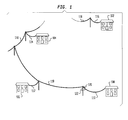
- Figure 1 shows power line 118 connected to individual residential units 102, 104, 106 and 108.
- the power line is connected to a transformer 120 which converts power from high voltage lines to power to be supplied to the residential units 102, 104, 106 and 108.
- Each of the residential units 102, 104, 106 and 108 are individually connected to the power line 118 through connection lines 116, 114, 112 and 110, respectively.
- a central transmitter/receiver 122 is coupled to the power line near the transformer 120.
- Figure 2 shows a schematic diagram of the connection of transformer 120 to the house 108.
- the secondary side of the transformer 120 includes three lines 208, 210 and 212.
- the lines 208 and 212 are power lines and the line 210 is a neutral line.
- the voltage between each of the power lines 208 and 212 and the neutral line 210 is at about 110 volts AC.
- the phase difference between the power lines 208 and 212 are about 180 degrees apart so that the voltage between the power lines 208 and 212 is about 220 volts AC.
- Signal choke blocks 214 and 216 are connected in series with the power lines 208 and 212, respectively at the transformer.
- the lines 210, 236 and 238 form a power line drop from the transformer 120 to the residential unit 108.
- the signal choke blocks 218 and 220 are connected in series to the power lines 236 and 238, respectively, at the residential unit end of the power line drop.
- the signal choke blocks 218 and 220 are also connected to power lines 240 and 242 that supply power to the residential unit 108.
- the signal choke blocks 214, 216, 218, and 220 are intended to isolate RF signals on the power line drop from impedance variations and noises from the transformer and the residential unit 108.
- the transmitter/receiver 122 and a transmitter/ receiver 202 are coupled to the power lines 236 and 238 via coupling capacitors 222-232.
- the transmitter/receiver 122 is also coupled to a communication network such as telephone network 234.
- the transmitter/receiver 202 is coupled to terminal(s) located within the residential unit 108. Thus, communication between the terminal(s) within the residential unit 108 and other terminal(s) coupled to the telephone network 234 may be accomplished.
- the signal choke blocks 214 and 216 decouple noise signals on the lines 208, 210 and 212 from the power lines 236 and 238.
- the signal choke block 218 and 220 decouple noise signals on the lines 240, 242 and 210 from the power lines 236 and 238.
- noise occurring in the communication bands generated by home appliances in the residential units 102, 104, 106 and 108 are blocked from interfering with the communication between transmitter/receivers 122 and 202.
- the transmitter/receivers 122 and 202 provide two duplex channels transmitting and receiving signals through the two power lines 236 and 238 and the neutral line 210.
- a first duplex channel transmits and receives signals in the same bands through the power line 236 and the neutral line 210 while a second duplex channel transmits and receives information in the same bands using the power line 238 and the neutral line 210.
- the neutral line 210 is shared between the first and the second duplex channels and the same frequency bands are used on both power-neutral line pairs 236 and 210, 238 and 210 for both transmit and receive signals. Because the neutral line 210 is shared, signals in the first duplex channel may be cross-coupled to the second duplex channel and vice versa. This cross-coupling reduces the signal-to-noise ratio so that transmission using two duplex channels is difficult without compensation. Thus, the cross-coupling through the neutral line 210 must be canceled before the two duplex channels can operate independently.
- the transmitter/receivers 122 and 202 cancel the cross-coupling between the first and second duplex channels as well as performing equalization of the transmission channels by using adaptive filters.
- the transmitter/receivers 122 and 202 are able to provide two duplex channel communication between the residential unit 108 and the telephone network 234 over the same frequency bands.
- the adaptive filters are described in detail below.
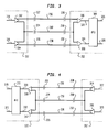
- FIGS 3 and 4 show a schematic diagram of the connection between line drivers and line receivers of the transmitter/receivers 122 and 202.
- the transmitter/receiver 122 includes differential line drivers 302 and 304 corresponding to the first and the second duplex channels forward inputs.
- the line driver 302 receives an input signal from signal line 318 and the line driver 304 receives an -input signal from input signal line 320.
- the line driver 302 outputs a differential signal between the power line 236 and the neutral line 210 through the coupling capacitors 222 and 224.
- the line driver 304 outputs a differential signal to the power line 238 and the neutral line 210 through coupling capacitors 226 and 224, respectively.
- Line receivers 306 and 308 of the transmitter/receiver 202 receives the signals transmitted by the transmitter/receiver 122 through the power lines 236 and 238 and the neutral line 210.
- the output of the line receivers 306 and 308 are connected to an adaptive filter unit 309 through signal lines 322 and 324.
- the adaptive filtering unit 309 performs line equalization and cross-coupling cancellation to improve the signal-to-noise ratios of the signals output to the signal lines 326 and 328 corresponding to the first and the second duplex channels forward outputs.
- Figure 4 shows a similar diagram as FIG. 3 but with the signals flowing in the opposite direction.
- Reverse inputs on 327 and 329 connected to line drivers 314 and 316 of the transmitter/receiver 202 transmit signals onto the power lines 236 and 238 and the neutral line 210.
- Line receivers 310 and 312 of the transmitter/receiver 122 receive the transmitted signals and output the received signals onto signal lines 330 and 332 to be input into adaptive filter unit 311.
- the adaptive filter unit 311 performs line equalization and cross-coupling cancellation to output received signals onto signal lines 319 and 321 corresponding to the first and the second duplex channel reverse outputs.
- FIG. 5 shows a block diagram of an adaptive filter unit such as the adaptive filter unit 309.
- the adaptive filter unit 309 includes four adaptive filters H 11 402, H 12 404, H 21 406 and H 22 408.
- the adaptive filter H 11 402 receives an input signal from the signal line 322 and outputs a filtered signal to a positive input of a summer 414 through signal line 340.
- the adaptive filter H 21 406 receives an input signal from signal line 324 and outputs a filtered signal to a negative input of the summer 414 through signal line 350.
- the summer 414 subtracts the output of the adaptive filter H 21 406 from the output of the adaptive filter H 11 402 to generate an output signal on the signal line 326.
- the adaptive filters H 11 402 and H 21 406 receive the output of the summer 414 as a feedback error signal through signal lines 342 and 348, respectively.
- data reference signals d 1 are input to a negative terminal of the summer 414.
- the data reference signals d 1 are required for H 11 402 to converge and may be data training sequence signals and/or decision feedbacks from final channel data decision outputs of a downstream receiver (not shown), for example.
- the adaptive filter H 22 408 receives an input signal from the signal line 324 and outputs a filtered signal to a positive input of a summer 416 through signal line 354.
- the adaptive filter H 12 404 receives an input signal from the signal line 322 and outputs a filtered signal to a negative input of summer 416 through signal line 344.
- the summer 416 subtracts the output from the adaptive filter H 12 404 from the output of the adaptive filter H 22 408 to generate an output signal on the signal line 328.
- the adaptive filters H 22 408 and H 12 404 receive the output of the summer 416 as a feedback error signal through signal lines 352 and 346, respectively. Similar to summer 414, data reference signals d 2 are input to a negative terminal of the summer 416 and are required for H 22 408 to converge.
- the adaptive filters H 11 402 and H 22 408 provide line equalization of the input signals received from the signal lines 322 and 324, respectively.
- the adaptive filters H 12 404 and H 21 406 adaptively cancel cross-coupling of the input signals between the signal lines 322 and 324 and the neutral line 210.
- FIG. 6 shows an exemplary embodiment of a linear adaptive filter such as the adaptive filters H 11 402, H 12 404, H 21 406 and H 22 408 in greater detail. While different adaptive filters may be used such as linear and decision feedback equalizers, FIG. 6 shows a finite-impulse-response (FIR) least-mean-square-error (MMSE) adaptive filter as an example.
- the filter portion 502 receives the input signal from signal line 322 and delays the input signal by delay units 520, 522 and 524. As indicated by the dotted portion of signal line 536, any number of delay units 520, 522 and 524 may be used depending on particular design requirements of the least-mean-square adaptive filter.
- FIR finite-impulse-response
- MMSE least-mean-square-error
- the delay units 520, 522 and 524 delay the input signal by some integer fraction of one symbol sub-unit time Ts/K.
- the delay units 520, 522 and 524, multiplier units 506, 508, 510 and 512 and adder units 514, 516 and 518 together form a filter that filters the input signal on signal line 322 and outputs the filtered input signal through signal line 328.
- the filter characteristics are determined by the weights W 1 , W 2 , W 3 , ... W M , where M is the length of the filter. Depending on the particular values of the weights, the frequency characteristic of the filter will be determined.
- the weights W 1 , W 2 ,...W M are adaptive weights.
- the adaptive weights are updated and the updated weights are used by the multipliers 506, 508, 510 and 512 as indicated by the lines connecting a weight update unit 504 and the multipliers 506, 508, 510 and 512.
- the weight update unit 504 calculates new weights based on the current set of weights adjusted by a factor which is a product of a constant g multiplied by the error signal ⁇ (j) multiplied by the input signal h(j), where j is the current time.
- the constant g is selected so that the weight update algorithm converges to generate an optimum set of weights W 1 , W 2 ...W M that results in the best signal-to-noise ratio within the constraint of adaptivity to changing system conditions.
- the error signal ⁇ (j) is the output of the summer 414 to adapt H 11 402 shown in Fig. 5, for example.
- the input signal h(j) is delayed corresponding to the total number of delays applied to the input signal by delay units 520, 522 and 524.
- the input signal used to update W 1 is an undelayed input signal h(j).
- W 2 is updated by using the input signal delayed by the delay unit 520, and so on.
- the weight update unit 504 generates weights adaptively to minimize, in the mean-square-error sense, the difference between the output of H 11 402 and the desired reference d 1 .
- a similar adaptive filter is used for H 21 406, and this is also adjusted by the error output of summer 414 to minimize the cross-coupled component in the final output 326.
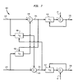
- FIG. 7 shows an adaptive filter unit 609 that is an alternative embodiment to the adaptive filter unit 309.
- the adaptive filter unit 609 includes the adaptive filters H 11 410, H12 404, H21 406 and H 22 412.
- the adaptive filter unit 609 also includes two summers 418 and 420 for cross terms and two summers 422 and 424 for referencing to desired data d 1 and d 2
- the adaptive filter H 11 410 is connected to the output of the summer 418 instead of between the signal line 322 and the summer 418 as in the adaptive filter unit 309.
- the adaptive filter H 22 412 is connected to the output of the summer 420.
- the adaptive filter unit 609 performs line equalization after canceling the cross-coupling between the signal lines 322 and 324.
- Figure 8 shows a hybrid line driver/receiver device 500 that includes an echo cancellation device 530 between signal lines 318 and 330 and a transmitter/receiver hybrid 532.
- the hybrid line driver/receiver device 500 performs a similar function as the line driver 302 and the line receiver 310 shown in FIG. 4.
- the transmitter/receiver hybrid 532 includes a differential line driver 513, a differential line receiver 509, and a balanced bridge 506.
- the echo cancellation device 530 includes an adaptive filter 514, a summer 510 and a buffer 511.
- the differential line driver 513 drives the balanced bridge circuit 506 at top and bottom nodes 518 and 520, respectively.
- the differential line receiver 509 receives signals from right and left bridge nodes 524 and 522.
- the output of the differential line receiver 509 is input to a positive input of the summer 510 through signal line 518.
- the adaptive filter 514 receives an input signal from signal line 318 and outputs a filtered signal to a negative input of the summer 510 through signal line 516.
- the summer 510 subtracts the filtered signal from the output of the differential line receiver 509 and outputs the result to the buffer 511 which generates an output to signal line 330.
- the adaptive filter receives the output of the summer 510 through signal line 512 as a feedback error signal.
- the adaptive filter 514 may be implemented using techniques such as linear and decision feedback equalizers and echo cancellers that are well known to one of ordinary skill in the art.
- the finite-impulse-response (FIR) least-mean square-error (MMSE) adaptive filter as shown in FIG. 6 may be used.
- the function of the adaptive filter 514 is to remove a signal correlated with the signal on line 318 that has been coupled to the signal line 518 via the differential line driver 513 and any imbalance in the balanced bridge circuit 506.
- the adaptive filter 514 adaptively adjusts weights so that the echo cancellation may account for variations in specific conditions encountered during operation.
- FIG. 9 shows a circuit diagram of the differential line driver 513 and the balanced bridge circuit 506.
- the differential line driver 513 may include two buffers 602 and 612 connected in voltage follower configurations together with resistors 606, 608 and 616.
- the positive input terminal of the buffer 612 is connected to a circuit ground reference via signal line 614.
- the positive terminal of the buffer 602 is connected to the signal line 318.
- a signal on the signal line 318 is applied differentially across the bridge nodes 518 and 520 and hence differentially across the power-neutral line pair 236 and 210.
- Resistors 606, 608 and 616 control the gain of the differential amplifier.
- the balanced bridge circuit 506 includes two legs between the nodes 518 and 520.
- the left leg includes a resistor 522 and an impedance 524.
- the right leg includes a resistor 520 and an impedance that is the driving point impedance looking into the power-neutral line pair 236 and 210.
- the resistors 520 and 522 have the same value and the impedance of 524 is assumed to have the same value as the line impedance across the frequency bands of interest for the RF signal transmission.
- the voltage between nodes 522 and 526 is unaffected when the balanced bridge circuit 506 is balanced. If a signal is received across the power-neutral line pair 236 and 210, the signal will be imaged across nodes 526 and 522. Thus, the voltage difference between the nodes 522 and 526 corresponds only to the signal received across power line 236 to neutral line 210 and does not contain a component of the signal between nodes 518 and 520 that is to be transmitted to the power-neutral line pair 236 and 210.
- the voltage between the nodes 522 and 526 is coupled to the differential line receiver 509 through signal lines 508 and 507.
- the balanced bridge circuit 506 permits transmitting signals out to the power-neutral line pair 236 and 210 and receiving signals from the power-neutral line pair 236 and 210 in the same bands and at the same time with minimal interference between the transmitted signal and the received signal.
- the value of the impedance 524 is determined based on the transmission line impedance seen looking into the power-neutral line pair 236 and 210.
- Figure 10 shows impedance values observed from arrows 702 and 704.
- the impedance 524 is set to the value of the impedance as observed from arrow 704 which includes: 1) the impedance of the transmission line as seen from arrow 702; 2) the equivalent impedance represented by the coupling capacitors 222 and 224 as well as the signal choke block 214; and 3) the impedance between power line 208 and the neutral line 210 representing the load of the transformer 120.
- 524 would be determined by the impedance observed looking into power-neutral line pair 236 and 210, the signal choke block 218, and impedance across power-neutral line pair 240 and 210 for application at the transmitter/receiver 202.
Landscapes
- Engineering & Computer Science (AREA)
- Computer Networks & Wireless Communication (AREA)
- Signal Processing (AREA)
- Cable Transmission Systems, Equalization Of Radio And Reduction Of Echo (AREA)
Abstract
Description
- This invention relates to power line communication systems that transmit and receive signals via power lines.
- Power lines are commonly connected to residential units using two power lines and one ground line. Communication signals may be transmitted using these power lines without requiring additional cabling. The number of physical channels has been limited by the number of wires, each of the physical channels requiring at least two wires. Previously, only one channel has been defined using the three wires. There is a need to increase the number of channels without requiring additional cabling.
- This invention provides two duplex channels using only two power lines and one neutral line. The transmitter/receiver of each duplex channel includes adaptive filters to cancel cross-coupling between the channels introduced by using the same neutral line for each of the duplex channels. Additionally, the channels are equalized by adaptive filters to compensate for channel distortions.
- Each of the duplex channels is coupled to its respective power-neutral line pair using a hybrid line driver/receiver device. The hybrid line driver/receiver device includes an echo canceller and a bridge circuit to allow transmitting and receiving signals to/from a single power-neutral line pair over the same frequency bands. The hybrid line driver/receiver device also includes a line driver and a line receiver. The echo canceller cancels transmitted signals that are coupled to the line receiver due to imperfections of the bridge circuit and the line driver.
- The adaptive filters and the hybrid line driver/receiver device increases signal-to-noise ratios of each duplex channel providing two duplex channels over three power lines. Thus, the communication bandwidth of power line communication systems is greatly increased over that previously obtained with power line carrier communication devices.
- The invention is described in relation to the following drawings wherein like numerals represent like elements, and wherein:
- FIG. 1 is a diagram of a power line system connecting residential units;
- FIG. 2 is a schematic diagram a communication system using power line connections between a residence and a transformer as a transmission medium;
- FIGS. 3 and 4 are schematic diagrams of transmitters/receivers in two directions using the same set of power lines;
- FIG. 5 is a schematic diagram of a first adaptive equalizer configuration used in the transmitter/receivers shown in FIGS. 3 and 4;
- FIG. 6 is a schematic diagram of a typical least-mean-square adaptive equalizer;
- FIG. 7 is a diagram of a second adaptive equalizer configuration;
- FIG. 8 is a schematic diagram of a combination of echo canceller and a hybrid line driver/receiver device for transmitting and receiving data;
- FIG. 9 is a schematic diagram of a hybrid circuit as presented in Figure 8; and
- FIG. 10 is a diagram of a power-neutral line pair.
-
- Figure 1 shows
power line 118 connected to individualresidential units transformer 120 which converts power from high voltage lines to power to be supplied to theresidential units residential units power line 118 throughconnection lines receiver 122 is coupled to the power line near thetransformer 120. - Figure 2 shows a schematic diagram of the connection of
transformer 120 to thehouse 108. The secondary side of thetransformer 120 includes threelines lines line 210 is a neutral line. For a conventional power line connection, the voltage between each of thepower lines neutral line 210 is at about 110 volts AC. However, the phase difference between thepower lines power lines -
Signal choke blocks power lines lines transformer 120 to theresidential unit 108. Thesignal choke blocks power lines signal choke blocks power lines residential unit 108. Thesignal choke blocks residential unit 108. - The transmitter/
receiver 122 and a transmitter/receiver 202 are coupled to thepower lines receiver 122 is also coupled to a communication network such astelephone network 234. The transmitter/receiver 202 is coupled to terminal(s) located within theresidential unit 108. Thus, communication between the terminal(s) within theresidential unit 108 and other terminal(s) coupled to thetelephone network 234 may be accomplished. - The
signal choke blocks lines power lines signal choke block lines power lines residential units receivers - The transmitter/
receivers power lines neutral line 210. A first duplex channel transmits and receives signals in the same bands through thepower line 236 and theneutral line 210 while a second duplex channel transmits and receives information in the same bands using thepower line 238 and theneutral line 210. Thus, theneutral line 210 is shared between the first and the second duplex channels and the same frequency bands are used on both power-neutral line pairs neutral line 210 is shared, signals in the first duplex channel may be cross-coupled to the second duplex channel and vice versa. This cross-coupling reduces the signal-to-noise ratio so that transmission using two duplex channels is difficult without compensation. Thus, the cross-coupling through theneutral line 210 must be canceled before the two duplex channels can operate independently. - The transmitter/
receivers receivers residential unit 108 and thetelephone network 234 over the same frequency bands. The adaptive filters are described in detail below. - Figures 3 and 4 show a schematic diagram of the connection between line drivers and line receivers of the transmitter/
receivers receiver 122 includesdifferential line drivers line driver 302 receives an input signal fromsignal line 318 and theline driver 304 receives an -input signal frominput signal line 320. Theline driver 302 outputs a differential signal between thepower line 236 and theneutral line 210 through thecoupling capacitors line driver 304 outputs a differential signal to thepower line 238 and theneutral line 210 throughcoupling capacitors -
Line receivers receiver 202 receives the signals transmitted by the transmitter/receiver 122 through thepower lines neutral line 210. The output of theline receivers adaptive filter unit 309 throughsignal lines adaptive filtering unit 309 performs line equalization and cross-coupling cancellation to improve the signal-to-noise ratios of the signals output to thesignal lines - Figure 4 shows a similar diagram as FIG. 3 but with the signals flowing in the opposite direction. Reverse inputs on 327 and 329 connected to line
drivers receiver 202 transmit signals onto thepower lines neutral line 210.Line receivers receiver 122 receive the transmitted signals and output the received signals ontosignal lines adaptive filter unit 311. Theadaptive filter unit 311 performs line equalization and cross-coupling cancellation to output received signals ontosignal lines - Figure 5 shows a block diagram of an adaptive filter unit such as the
adaptive filter unit 309. Theadaptive filter unit 309 includes fouradaptive filters H 11 402,H 12 404,H 21 406 andH 22 408. Theadaptive filter H 11 402 receives an input signal from thesignal line 322 and outputs a filtered signal to a positive input of asummer 414 throughsignal line 340. Theadaptive filter H 21 406 receives an input signal fromsignal line 324 and outputs a filtered signal to a negative input of thesummer 414 throughsignal line 350. Thus, thesummer 414 subtracts the output of theadaptive filter H 21 406 from the output of theadaptive filter H 11 402 to generate an output signal on thesignal line 326. Theadaptive filters H 11 402 andH 21 406 receive the output of thesummer 414 as a feedback error signal throughsignal lines - In addition, data reference signals d1 are input to a negative terminal of the
summer 414. The data reference signals d1 are required forH 11 402 to converge and may be data training sequence signals and/or decision feedbacks from final channel data decision outputs of a downstream receiver (not shown), for example. - The
adaptive filter H 22 408 receives an input signal from thesignal line 324 and outputs a filtered signal to a positive input of asummer 416 throughsignal line 354. Theadaptive filter H 12 404 receives an input signal from thesignal line 322 and outputs a filtered signal to a negative input ofsummer 416 throughsignal line 344. Thus, thesummer 416 subtracts the output from theadaptive filter H 12 404 from the output of theadaptive filter H 22 408 to generate an output signal on thesignal line 328. Theadaptive filters H 22 408 andH 12 404 receive the output of thesummer 416 as a feedback error signal throughsignal lines summer 414, data reference signals d2 are input to a negative terminal of thesummer 416 and are required forH 22 408 to converge. - The
adaptive filters H 11 402 andH 22 408 provide line equalization of the input signals received from thesignal lines adaptive filters H 12 404 andH 21 406 adaptively cancel cross-coupling of the input signals between thesignal lines neutral line 210. - Figure 6 shows an exemplary embodiment of a linear adaptive filter such as the
adaptive filters H 11 402,H 12 404,H 21 406 andH 22 408 in greater detail. While different adaptive filters may be used such as linear and decision feedback equalizers, FIG. 6 shows a finite-impulse-response (FIR) least-mean-square-error (MMSE) adaptive filter as an example. Thefilter portion 502 receives the input signal fromsignal line 322 and delays the input signal bydelay units signal line 536, any number ofdelay units delay units - The
delay units multiplier units adder units signal line 322 and outputs the filtered input signal throughsignal line 328. The filter characteristics are determined by the weights W1, W2, W3, ... WM, where M is the length of the filter. Depending on the particular values of the weights, the frequency characteristic of the filter will be determined. - The weights W1, W2,...WM are adaptive weights. The adaptive weights are updated and the updated weights are used by the
multipliers weight update unit 504 and themultipliers - The
weight update unit 504 calculates new weights based on the current set of weights adjusted by a factor which is a product of a constant g multiplied by the error signal ∈(j) multiplied by the input signal h(j), where j is the current time. The constant g is selected so that the weight update algorithm converges to generate an optimum set of weights W1, W2...WM that results in the best signal-to-noise ratio within the constraint of adaptivity to changing system conditions. The error signal ∈(j) is the output of thesummer 414 to adaptH 11 402 shown in Fig. 5, for example. The input signal h(j) is delayed corresponding to the total number of delays applied to the input signal bydelay units delay unit 520, and so on. Theweight update unit 504 generates weights adaptively to minimize, in the mean-square-error sense, the difference between the output ofH 11 402 and the desired reference d1. A similar adaptive filter is used forH 21 406, and this is also adjusted by the error output ofsummer 414 to minimize the cross-coupled component in thefinal output 326. - Figure 7 shows an
adaptive filter unit 609 that is an alternative embodiment to theadaptive filter unit 309. Theadaptive filter unit 609 includes theadaptive filters H 11 410,H12 404,H21 406 andH 22 412. Theadaptive filter unit 609 also includes twosummers adaptive filter H 11 410 is connected to the output of thesummer 418 instead of between thesignal line 322 and thesummer 418 as in theadaptive filter unit 309. Similarly, theadaptive filter H 22 412 is connected to the output of thesummer 420. Thus, theadaptive filter unit 609 performs line equalization after canceling the cross-coupling between thesignal lines - Figure 8 shows a hybrid line driver/
receiver device 500 that includes anecho cancellation device 530 betweensignal lines receiver hybrid 532. The hybrid line driver/receiver device 500 performs a similar function as theline driver 302 and theline receiver 310 shown in FIG. 4. The transmitter/receiver hybrid 532 includes adifferential line driver 513, adifferential line receiver 509, and abalanced bridge 506. Theecho cancellation device 530 includes anadaptive filter 514, asummer 510 and abuffer 511. Thedifferential line driver 513 drives thebalanced bridge circuit 506 at top andbottom nodes differential line receiver 509 receives signals from right and leftbridge nodes differential line receiver 509 is input to a positive input of thesummer 510 throughsignal line 518. Theadaptive filter 514 receives an input signal fromsignal line 318 and outputs a filtered signal to a negative input of thesummer 510 throughsignal line 516. Thesummer 510 subtracts the filtered signal from the output of thedifferential line receiver 509 and outputs the result to thebuffer 511 which generates an output to signalline 330. The adaptive filter receives the output of thesummer 510 throughsignal line 512 as a feedback error signal. - The
adaptive filter 514 may be implemented using techniques such as linear and decision feedback equalizers and echo cancellers that are well known to one of ordinary skill in the art. For example, the finite-impulse-response (FIR) least-mean square-error (MMSE) adaptive filter as shown in FIG. 6 may be used. The function of theadaptive filter 514 is to remove a signal correlated with the signal online 318 that has been coupled to thesignal line 518 via thedifferential line driver 513 and any imbalance in thebalanced bridge circuit 506. Theadaptive filter 514 adaptively adjusts weights so that the echo cancellation may account for variations in specific conditions encountered during operation. - Figure 9 shows a circuit diagram of the
differential line driver 513 and thebalanced bridge circuit 506. Thedifferential line driver 513 may include twobuffers resistors buffer 612 is connected to a circuit ground reference viasignal line 614. Thus, the output of thebuffer 612 is maintained at the voltage of the ground reference so that thesignal line 504 is at this reference voltage. The positive terminal of thebuffer 602 is connected to thesignal line 318. Then a signal on thesignal line 318 is applied differentially across thebridge nodes neutral line pair Resistors - The
balanced bridge circuit 506 includes two legs between thenodes resistor 522 and animpedance 524. The right leg includes aresistor 520 and an impedance that is the driving point impedance looking into the power-neutral line pair resistors - When a voltage is developed between the
nodes nodes balanced bridge circuit 506 is balanced. If a signal is received across the power-neutral line pair nodes nodes power line 236 toneutral line 210 and does not contain a component of the signal betweennodes neutral line pair - The voltage between the
nodes differential line receiver 509 throughsignal lines balanced bridge circuit 506 permits transmitting signals out to the power-neutral line pair neutral line pair - The value of the
impedance 524 is determined based on the transmission line impedance seen looking into the power-neutral line pair arrows transformer 120 and of the system in Figure 2, theimpedance 524 is set to the value of the impedance as observed fromarrow 704 which includes: 1) the impedance of the transmission line as seen fromarrow 702; 2) the equivalent impedance represented by thecoupling capacitors signal choke block 214; and 3) the impedance betweenpower line 208 and theneutral line 210 representing the load of thetransformer 120. Similarly, 524 would be determined by the impedance observed looking into power-neutral line pair signal choke block 218, and impedance across power-neutral line pair receiver 202. - While this invention has been described in conjunction with specific embodiments thereof, it is evident that many alternatives, modifications and variations would be apparent to those skilled in the art. Accordingly, preferred embodiments of the invention as set forth herein are intended to be illustrative not limiting. Various changes may be made without departing from the spirit and scope of the invention as defined in the following claims.
Claims (15)
- A power line communications system, comprising:a first power line and a second power line;a neutral line;a transmitter/receiver coupled to the neutral line and the first and the second power lines, the transmitter/receiver transmitting and receiving information using the first power line and the neutral line as a first channel and the second power line and the neutral line as a second channel, wherein the first channel is independent of the second channel.
- The system of claim 1, wherein the transmitter/receiver comprises:a first receiver coupled to the first power line and the neutral line, the first receiver generating a first output;a second receiver coupled to the second power line and the neutral line, the second receiver generating a second output; andan equalizing device coupled to the first and the second receivers, the equalizing device receiving the first and the second outputs and generating a first channel output and a second channel output.
- The system of claim 2, wherein the equalizing device comprises:a first equalizer receiving the first output of the first receiver and generating a first equalizer output;a second equalizer receiving the second output of the second receiver and generating a second equalizer output;a first summer subtracting the second equalizer output from the first equalizer output to generate the first channel output;a third equalizer receiving the first output of the first receiver and generating a third equalizer output;a fourth equalizer receiving the second output of the second receiver and generating a fourth equalizer output; anda second summer subtracting the third equalizer output from the fourth equalizer output to generate the second channel output.
- The system of claim 2, wherein the equalizing device comprises:a first equalizer receiving the second output of the second receiver and generating a first equalizer output;a first summer subtracting the first equalizer output from the first output of the first receiver to generate a first summer output;a second equalizer receiving the first summer output and generating the first channel output;a third equalizer receiving the first output of the first receiver and generating a third equalizer output;a second summer subtracting the third equalizer output from the second output of the second receiver to generate a second summer output; anda fourth equalizer receiving the second summer output and generating the second channel output.
- The system of claim 1, wherein the transmitter/receiver comprises:a transmitter;a receiver;a hybrid circuit coupled to the transmitter, the receiver and one of the first and the second channels as a data channel, the hybrid circuit transmitting data to and receiving the data from the data channel.
- The system of claim 1, wherein the transmitter/receiver comprises:a transmitter;a receiver; andan echo canceller coupled to the transmitter and the receiver, wherein the echo canceller cancels signals transmitted by the transmitter from signals received by the receiver.
- The system of claim 1, further comprising a plurality of decoupling devices, a first portion of the decoupling devices being connected in-line to the first power line and a second portion of the decoupling devices being connected in-line to the second power line, the transmitter/receiver being coupled to the first and the second power lines between two of the decoupling devices.
- The system of claim 1, wherein the first and the second channels are duplex channels.
- A method for operating a power line communications system, comprising:transmitting first information through a first power line and a neutral line;transmitting second information through a second power line and the neutral line;receiving third information through the first power line and the neutral line; andreceiving fourth information through the second power line and the neutral line, wherein the first power line and the neutral line forms a first channel, and the second power line and the neutral line forms a second channel, the first channel being independent of the second channel.
- The method of claim 9, further comprising:generating a first output from the first channel;generating a second output from the second channel; andequalizing the first and the second outputs to generate a first channel output and a second channel output.
- The method of claim 10, wherein the equalizing step comprises:equalizing the first output to generate a first equalized output;equalizing the second output to generate a second equalized output;subtracting the second equalized output from the first equalized to generate the first channel output;equalizing the first output to generate a third equalized output;equalizing the second output to generate a fourth equalized output; andsubtracting the third equalized output from the fourth equalized to generate the second channel output;
- The method of claim 10, wherein the equalizing step comprises:equalizing the second output to generate a first equalized output;subtracting the first equalized output from the first output to generate a first summer output;equalizing the first summer output to generate the first channel output;equalizing the first output to generate a third equalized output;subtracting the third equalized output from the second output to generate a second summer output; andequalizing the second summer output to generate the second channel output.
- The method of claim 9, wherein the first and third information are transmitted and received over the first channel through a first hybrid circuit, and the second and fourth information are transmitted and received over the second channel through a second hybrid circuit.
- The method of claim 9, further comprising:echo cancelling the first information from the third information; andecho cancelling the second information from the fourth information.
- The method of claim 9, further comprising decoupling the first and second power lines by placing decoupling devices in-line to the first and the second power lines, wherein the first and the second information are transmitted and the third and fourth information are received from the first and the second power lines between the decoupling devices.
Applications Claiming Priority (2)
| Application Number | Priority Date | Filing Date | Title |
|---|---|---|---|
| US08/926,609 US5952914A (en) | 1997-09-10 | 1997-09-10 | Power line communication systems |
| US926609 | 1997-09-10 |
Publications (2)
| Publication Number | Publication Date |
|---|---|
| EP0902550A2 true EP0902550A2 (en) | 1999-03-17 |
| EP0902550A3 EP0902550A3 (en) | 2000-01-26 |
Family
ID=25453443
Family Applications (1)
| Application Number | Title | Priority Date | Filing Date |
|---|---|---|---|
| EP98306830A Withdrawn EP0902550A3 (en) | 1997-09-10 | 1998-08-26 | Power line communication systems |
Country Status (2)
| Country | Link |
|---|---|
| US (1) | US5952914A (en) |
| EP (1) | EP0902550A3 (en) |
Cited By (5)
| Publication number | Priority date | Publication date | Assignee | Title |
|---|---|---|---|---|
| KR20020032024A (en) * | 2000-10-25 | 2002-05-03 | 이기원 | Apparatus For optimizing emergency power source in order to powerline Communication and method therefore |
| WO2003107559A1 (en) * | 2002-06-13 | 2003-12-24 | Infineon Technologies Ag | Method and device for determining the electrical properties of a data line |
| FR2843253A1 (en) * | 2002-07-30 | 2004-02-06 | Infineon Technologies Ag | TRANSCEIVER HAVING AN INTEGRATED HYBRID CIRCUIT |
| DE102005030368A1 (en) * | 2005-06-29 | 2006-09-21 | Siemens Ag | Bi-directional communication method for communication unit, involves performing full duplex communication between transmitter and receiver in communication unit, and launching transmission signals out-of phase in receiver section |
| EP1775851A1 (en) * | 2005-10-13 | 2007-04-18 | Vierling Communications GmbH | Crosstalk compensation circuit, unit and method |
Families Citing this family (68)
| Publication number | Priority date | Publication date | Assignee | Title |
|---|---|---|---|---|
| US6452482B1 (en) * | 1999-12-30 | 2002-09-17 | Ambient Corporation | Inductive coupling of a data signal to a power transmission cable |
| US6323756B1 (en) * | 1997-09-02 | 2001-11-27 | Matsushita Electric Industrial Co., Ltd. | Data transmitter |
| US6154488A (en) * | 1997-09-23 | 2000-11-28 | Hunt Technologies, Inc. | Low frequency bilateral communication over distributed power lines |
| US6480510B1 (en) | 1998-07-28 | 2002-11-12 | Serconet Ltd. | Local area network of serial intelligent cells |
| DE19907538C2 (en) * | 1999-02-22 | 2001-02-22 | Siemens Ag | Communication system |
| US6297729B1 (en) * | 1999-03-29 | 2001-10-02 | International Business Machines Corporation | Method and apparatus for securing communications along ac power lines |
| AU1371900A (en) | 1999-12-08 | 2001-06-18 | Ascom Powerline Communications Ag | Assembly for transmitting information via a low-voltage power supply network |
| US7154382B2 (en) | 1999-12-30 | 2006-12-26 | Ambient Corporation | Arrangement of inductive couplers for data communication |
| US7176786B2 (en) * | 2000-01-20 | 2007-02-13 | Current Technologies, Llc | Method of isolating data in a power line communications network |
| BR0108032A (en) * | 2000-01-20 | 2003-04-08 | Current Tech Llc | System, network coupler, and network isolator for isolating data in a power line communication network |
| US6998962B2 (en) | 2000-04-14 | 2006-02-14 | Current Technologies, Llc | Power line communication apparatus and method of using the same |
| US6965302B2 (en) * | 2000-04-14 | 2005-11-15 | Current Technologies, Llc | Power line communication system and method of using the same |
| US20020110311A1 (en) * | 2001-02-14 | 2002-08-15 | Kline Paul A. | Apparatus and method for providing a power line communication device for safe transmission of high-frequency, high-bandwidth signals over existing power distribution lines |
| US7103240B2 (en) * | 2001-02-14 | 2006-09-05 | Current Technologies, Llc | Method and apparatus for providing inductive coupling and decoupling of high-frequency, high-bandwidth data signals directly on and off of a high voltage power line |
| US6842459B1 (en) | 2000-04-19 | 2005-01-11 | Serconet Ltd. | Network combining wired and non-wired segments |
| KR100374154B1 (en) * | 2000-06-24 | 2003-02-26 | 장학선 | System for receiving and transmitting power signal and data signal |
| US6492897B1 (en) | 2000-08-04 | 2002-12-10 | Richard A. Mowery, Jr. | System for coupling wireless signals to and from a power transmission line communication system |
| US6791454B2 (en) * | 2000-11-17 | 2004-09-14 | Siemens Aktiengesellschaft | Cable |
| US6590493B1 (en) * | 2000-12-05 | 2003-07-08 | Nortel Networks Limited | System, device, and method for isolating signaling environments in a power line communication system |
| US7170405B2 (en) * | 2000-12-26 | 2007-01-30 | General Electric Company | Method and apparatus for interfacing a power line carrier and an appliance |
| US20030046377A1 (en) * | 2000-12-27 | 2003-03-06 | Wolfgang Daum | Method and apparatus for appliance service diagnostics |
| US7173938B1 (en) | 2001-05-18 | 2007-02-06 | Current Grid, Llc | Method and apparatus for processing outbound data within a powerline based communication system |
| US7194528B1 (en) | 2001-05-18 | 2007-03-20 | Current Grid, Llc | Method and apparatus for processing inbound data within a powerline based communication system |
| US7173935B2 (en) * | 2002-06-07 | 2007-02-06 | Current Grid, Llc | Last leg utility grid high-speed data communication network having virtual local area network functionality |
| JP3713477B2 (en) * | 2001-11-19 | 2005-11-09 | Tdk株式会社 | Power line communication system |
| NZ517321A (en) * | 2002-02-21 | 2003-02-28 | Rutherford J G | A communications system utilising electricity cabling |
| CN1653794A (en) * | 2002-03-14 | 2005-08-10 | 安比恩特公司 | Protecting medium voltage inductive coupled device from electrical transients |
| US20030189495A1 (en) * | 2002-04-03 | 2003-10-09 | Pettler Peter R. | Method and system for controlling a selected electrical load in a building |
| US6741045B2 (en) | 2002-04-23 | 2004-05-25 | Shimano, Inc. | Bicycle control apparatus that communicates power and data over a single transmission path |
| US6982611B2 (en) * | 2002-06-24 | 2006-01-03 | Current Technologies, Llc | Power line coupling device and method of using the same |
| US7340509B2 (en) | 2002-07-18 | 2008-03-04 | General Electric Company | Reconfigurable appliance control system |
| US6727804B1 (en) | 2002-07-23 | 2004-04-27 | Domosys Corporation | Power line communication system and method |
| US7622891B2 (en) * | 2002-10-28 | 2009-11-24 | Access Business Group International Llc | Contact-less power transfer |
| US20060152344A1 (en) * | 2002-12-07 | 2006-07-13 | Mowery Richard A Jr | Powerline Communication Network Handoff |
| US6980090B2 (en) * | 2002-12-10 | 2005-12-27 | Current Technologies, Llc | Device and method for coupling with electrical distribution network infrastructure to provide communications |
| US7224272B2 (en) * | 2002-12-10 | 2007-05-29 | Current Technologies, Llc | Power line repeater system and method |
| US6980091B2 (en) * | 2002-12-10 | 2005-12-27 | Current Technologies, Llc | Power line communication system and method of operating the same |
| IL154921A (en) | 2003-03-13 | 2011-02-28 | Mosaid Technologies Inc | Telephone system having multiple distinct sources and accessories therefor |
| US20060291575A1 (en) * | 2003-07-03 | 2006-12-28 | Berkman William H | Power Line Communication System and Method |
| US7321291B2 (en) * | 2004-10-26 | 2008-01-22 | Current Technologies, Llc | Power line communications system and method of operating the same |
| US7852837B1 (en) | 2003-12-24 | 2010-12-14 | At&T Intellectual Property Ii, L.P. | Wi-Fi/BPL dual mode repeaters for power line networks |
| US7369607B2 (en) * | 2004-02-26 | 2008-05-06 | 2Wire, Inc. | Multicarrier communication using a time domain equalizing filter |
| US7091849B1 (en) | 2004-05-06 | 2006-08-15 | At&T Corp. | Inbound interference reduction in a broadband powerline system |
| EP1805927A1 (en) | 2004-10-11 | 2007-07-11 | 2Wire, Inc. | Periodic impulse noise mitigation in a dsl system |
| US7953163B2 (en) | 2004-11-30 | 2011-05-31 | Broadcom Corporation | Block linear equalization in a multicarrier communication system |
| US8462902B1 (en) | 2004-12-01 | 2013-06-11 | At&T Intellectual Property Ii, L.P. | Interference control in a broadband powerline communication system |
| US9172429B2 (en) | 2004-12-01 | 2015-10-27 | At&T Intellectual Property Ii, L.P. | Interference control in a broadband powerline communication system |
| US7852950B2 (en) | 2005-02-25 | 2010-12-14 | Broadcom Corporation | Methods and apparatuses for canceling correlated noise in a multi-carrier communication system |
| US9374257B2 (en) | 2005-03-18 | 2016-06-21 | Broadcom Corporation | Methods and apparatuses of measuring impulse noise parameters in multi-carrier communication systems |
| US7265664B2 (en) | 2005-04-04 | 2007-09-04 | Current Technologies, Llc | Power line communications system and method |
| US20060255930A1 (en) * | 2005-05-12 | 2006-11-16 | Berkman William H | Power line communications system and method |
| US7215245B2 (en) * | 2005-05-31 | 2007-05-08 | Fu Ching Lee | Activator circuit responsive to power line disturbances |
| US7675897B2 (en) | 2005-09-06 | 2010-03-09 | Current Technologies, Llc | Power line communications system with differentiated data services |
| US7813439B2 (en) | 2006-02-06 | 2010-10-12 | Broadcom Corporation | Various methods and apparatuses for impulse noise detection |
| US7764943B2 (en) | 2006-03-27 | 2010-07-27 | Current Technologies, Llc | Overhead and underground power line communication system and method using a bypass |
| US7714682B2 (en) * | 2007-06-21 | 2010-05-11 | Current Technologies, Llc | Power line data signal attenuation device and method |
| US7795994B2 (en) * | 2007-06-26 | 2010-09-14 | Current Technologies, Llc | Power line coupling device and method |
| US7876174B2 (en) | 2007-06-26 | 2011-01-25 | Current Technologies, Llc | Power line coupling device and method |
| US20090109981A1 (en) * | 2007-10-25 | 2009-04-30 | Michael Keselman | Out-of-band management for broadband over powerline network |
| US20090124209A1 (en) * | 2007-11-08 | 2009-05-14 | Michael Keselman | Methods and system for configuration of broadband over power lines |
| US20090125255A1 (en) * | 2007-11-08 | 2009-05-14 | Michael Keselman | Methods and apparatus for measuring voltage and voltage phase angle on bpl line |
| US20090153133A1 (en) * | 2007-12-13 | 2009-06-18 | Michael Keselman | Methods and apparatus for collecting characteristics of a power line a bpl system |
| US8605837B2 (en) | 2008-10-10 | 2013-12-10 | Broadcom Corporation | Adaptive frequency-domain reference noise canceller for multicarrier communications systems |
| US8279058B2 (en) | 2008-11-06 | 2012-10-02 | Current Technologies International Gmbh | System, device and method for communicating over power lines |
| US20110018704A1 (en) * | 2009-07-24 | 2011-01-27 | Burrows Zachary M | System, Device and Method for Providing Power Line Communications |
| US8265197B2 (en) * | 2009-08-03 | 2012-09-11 | Texas Instruments Incorporated | OFDM transmission methods in three phase modes |
| WO2011025934A2 (en) * | 2009-08-28 | 2011-03-03 | Enphase Energy, Inc. | Power line communications apparatus |
| JP5211102B2 (en) | 2010-04-28 | 2013-06-12 | 株式会社シマノ | Bicycle electrical system |
Citations (2)
| Publication number | Priority date | Publication date | Assignee | Title |
|---|---|---|---|---|
| US4357598A (en) * | 1981-04-09 | 1982-11-02 | Westinghouse Electric Corp. | Three-phase power distribution network communication system |
| US4668934A (en) * | 1984-10-22 | 1987-05-26 | Westinghouse Electric Corp. | Receiver apparatus for three-phase power line carrier communications |
Family Cites Families (18)
| Publication number | Priority date | Publication date | Assignee | Title |
|---|---|---|---|---|
| US3942168A (en) * | 1975-01-31 | 1976-03-02 | Westinghouse Electric Corporation | Distribution network power line communication system |
| US4060735A (en) * | 1976-07-12 | 1977-11-29 | Johnson Controls, Inc. | Control system employing a programmable multiple channel controller for transmitting control signals over electrical power lines |
| US4142178A (en) * | 1977-04-25 | 1979-02-27 | Westinghouse Electric Corp. | High voltage signal coupler for a distribution network power line carrier communication system |
| US4311964A (en) * | 1979-09-21 | 1982-01-19 | Westinghouse Electric Corp. | Coherent phase shift keyed demodulator for power line communication systems |
| US4479215A (en) * | 1982-09-24 | 1984-10-23 | General Electric Company | Power-line carrier communications system with interference avoidance capability |
| US4514594A (en) * | 1982-09-30 | 1985-04-30 | Astech, Inc. | Power line carrier telephone extension system for full duplex conferencing between telephones and having telephone call hold capability |
| US4475193A (en) * | 1982-09-30 | 1984-10-02 | Astech, Inc. | Power line carrier multi telephone extension system for full duplex conferencing between telephones |
| US4510611A (en) * | 1982-11-19 | 1985-04-09 | General Electric Company | Transceiver circuit for interfacing between a power line communication system and a data processor |
| US4633218A (en) * | 1983-12-19 | 1986-12-30 | Honeywell Inc. | Apparatus for receiving low level digital signals transmitted over power lines |
| US5066939A (en) * | 1989-10-04 | 1991-11-19 | Mansfield Jr Amos R | Method and means of operating a power line carrier communication system |
| US5257006A (en) * | 1990-09-21 | 1993-10-26 | Echelon Corporation | Method and apparatus for power line communications |
| US5581229A (en) * | 1990-12-19 | 1996-12-03 | Hunt Technologies, Inc. | Communication system for a power distribution line |
| WO1992021194A1 (en) * | 1991-05-10 | 1992-11-26 | Echelon Corporation | Power line communication while avoiding determinable interference harmonics |
| GB9222205D0 (en) * | 1992-10-22 | 1992-12-02 | Norweb Plc | Low voltage filter |
| US5491463A (en) * | 1993-06-28 | 1996-02-13 | Advanced Control Technologies, Inc. | Power line communication system |
| US5391932A (en) * | 1993-07-20 | 1995-02-21 | Echelon Corporation | Source power coupler |
| US5694108A (en) * | 1996-05-01 | 1997-12-02 | Abb Power T&D Company Inc. | Apparatus and methods for power network coupling |
| US5691691A (en) * | 1997-01-06 | 1997-11-25 | Motorola, Inc. | Power-line communication system using pulse transmission on the AC line |
-
1997
- 1997-09-10 US US08/926,609 patent/US5952914A/en not_active Expired - Lifetime
-
1998
- 1998-08-26 EP EP98306830A patent/EP0902550A3/en not_active Withdrawn
Patent Citations (2)
| Publication number | Priority date | Publication date | Assignee | Title |
|---|---|---|---|---|
| US4357598A (en) * | 1981-04-09 | 1982-11-02 | Westinghouse Electric Corp. | Three-phase power distribution network communication system |
| US4668934A (en) * | 1984-10-22 | 1987-05-26 | Westinghouse Electric Corp. | Receiver apparatus for three-phase power line carrier communications |
Cited By (9)
| Publication number | Priority date | Publication date | Assignee | Title |
|---|---|---|---|---|
| KR20020032024A (en) * | 2000-10-25 | 2002-05-03 | 이기원 | Apparatus For optimizing emergency power source in order to powerline Communication and method therefore |
| WO2003107559A1 (en) * | 2002-06-13 | 2003-12-24 | Infineon Technologies Ag | Method and device for determining the electrical properties of a data line |
| FR2843253A1 (en) * | 2002-07-30 | 2004-02-06 | Infineon Technologies Ag | TRANSCEIVER HAVING AN INTEGRATED HYBRID CIRCUIT |
| GB2392360A (en) * | 2002-07-30 | 2004-02-25 | Infineon Technologies Ag | Transceiver with integrated hybrid circuit |
| GB2392360B (en) * | 2002-07-30 | 2004-10-13 | Infineon Technologies Ag | Transceiver with integrated hybrid circuit |
| CN100386967C (en) * | 2002-07-30 | 2008-05-07 | 印芬龙科技股份有限公司 | Transceiver with integrated hybrid circuit |
| US7486788B2 (en) | 2002-07-30 | 2009-02-03 | Infineon Technologies Ag | Transceiver with integrated hybrid circuit |
| DE102005030368A1 (en) * | 2005-06-29 | 2006-09-21 | Siemens Ag | Bi-directional communication method for communication unit, involves performing full duplex communication between transmitter and receiver in communication unit, and launching transmission signals out-of phase in receiver section |
| EP1775851A1 (en) * | 2005-10-13 | 2007-04-18 | Vierling Communications GmbH | Crosstalk compensation circuit, unit and method |
Also Published As
| Publication number | Publication date |
|---|---|
| US5952914A (en) | 1999-09-14 |
| EP0902550A3 (en) | 2000-01-26 |
Similar Documents
| Publication | Publication Date | Title |
|---|---|---|
| US5952914A (en) | Power line communication systems | |
| US7738654B2 (en) | Isolation of transmit and receive signals | |
| US7567666B2 (en) | Method and apparatus for crosstalk mitigation | |
| CN101300822B (en) | Isolation of transmit and receive signals | |
| US8880017B1 (en) | Active resistive summer for a transformer hybrid | |
| JP5229318B2 (en) | Single port signal repeater | |
| US6313738B1 (en) | Adaptive noise cancellation system | |
| EP0768779A2 (en) | Suppression of distortion and interference in in multiple acces communication systems | |
| US6912208B2 (en) | Method and apparatus for equalization and crosstalk mitigation | |
| JPH0767104B2 (en) | Complete duplex data transmission device by 2-wire line | |
| WO2005036761A2 (en) | System, method and apparatus for crosstalk cancellation | |
| EP2503704B1 (en) | Method and apparatus for equalization and crosstalk mitigation | |
| GB1563541A (en) | Signal transmission circuit | |
| MXPA04010733A (en) | Full duplexing for power line data communications. | |
| US4163878A (en) | Electronic hybrid and hybrid repeater with bridge circuit | |
| US7010025B1 (en) | Circuit and method for an improved front end in duplex signal communication systems | |
| JP2004236317A (en) | Method and apparatus for reducing noise in unbalanced channel using common mode component | |
| US8989251B2 (en) | Method and apparatus to compensate for nonlinear echo in an output of a current source | |
| US20010024498A1 (en) | Method and apparatus for an improved analog echo canceller | |
| US7200371B1 (en) | Inter-modulation interference inhibiting line amplifier | |
| US7020277B1 (en) | DSL line interface having low-pass filter characteristic with reduced external components | |
| JP2003513585A (en) | Echo compensation device | |
| JPS6046862B2 (en) | loss compensation circuit | |
| JPH10126817A (en) | 2-line to 4-line converting circuit |
Legal Events
| Date | Code | Title | Description |
|---|---|---|---|
| PUAI | Public reference made under article 153(3) epc to a published international application that has entered the european phase |
Free format text: ORIGINAL CODE: 0009012 |
|
| AK | Designated contracting states |
Kind code of ref document: A2 Designated state(s): DE FR GB |
|
| AX | Request for extension of the european patent |
Free format text: AL;LT;LV;MK;RO;SI |
|
| 17P | Request for examination filed |
Effective date: 19990607 |
|
| PUAL | Search report despatched |
Free format text: ORIGINAL CODE: 0009013 |
|
| RIC1 | Information provided on ipc code assigned before grant |
Free format text: 7H 04B 3/54 A, 7H 04B 3/56 B |
|
| AK | Designated contracting states |
Kind code of ref document: A3 Designated state(s): AT BE CH CY DE DK ES FI FR GB GR IE IT LI LU MC NL PT SE |
|
| AX | Request for extension of the european patent |
Free format text: AL;LT;LV;MK;RO;SI |
|
| AKX | Designation fees paid |
Free format text: DE FR GB |
|
| STAA | Information on the status of an ep patent application or granted ep patent |
Free format text: STATUS: THE APPLICATION IS DEEMED TO BE WITHDRAWN |
|
| 18D | Application deemed to be withdrawn |
Effective date: 20030301 |