EP0902385A2 - Early thermal printhead failure prediction system - Google Patents
Early thermal printhead failure prediction system Download PDFInfo
- Publication number
- EP0902385A2 EP0902385A2 EP98115925A EP98115925A EP0902385A2 EP 0902385 A2 EP0902385 A2 EP 0902385A2 EP 98115925 A EP98115925 A EP 98115925A EP 98115925 A EP98115925 A EP 98115925A EP 0902385 A2 EP0902385 A2 EP 0902385A2
- Authority
- EP
- European Patent Office
- Prior art keywords
- trend
- resistance
- printing
- resistive
- characteristic
- Prior art date
- Legal status (The legal status is an assumption and is not a legal conclusion. Google has not performed a legal analysis and makes no representation as to the accuracy of the status listed.)
- Granted
Links
Images
Classifications
-
- G—PHYSICS
- G06—COMPUTING OR CALCULATING; COUNTING
- G06K—GRAPHICAL DATA READING; PRESENTATION OF DATA; RECORD CARRIERS; HANDLING RECORD CARRIERS
- G06K1/00—Methods or arrangements for marking the record carrier in digital fashion
- G06K1/12—Methods or arrangements for marking the record carrier in digital fashion otherwise than by punching
- G06K1/126—Methods or arrangements for marking the record carrier in digital fashion otherwise than by punching by photographic or thermographic registration
Definitions
- the present invention is directed to a thermal printer for printing tags and/or labels and more particularly to such a printer and method for predicting thermal printhead failure.
- thermal label/tag printers include thermal printheads containing individual printing elements 23. When a printing element fails, it may result in a discontinuity in the printing.
- Prior thermal label printers have used data dot shift routines to shift data around a failed printing element so that the failed printing element is aligned with "zero" print data. This feature extends the useful life of a thermal printhead. However, such routines do not provide any warning as to when a printing element is failing.
- the early thermal printhead failure prediction system of the present invention is directed to overcome the limitations of the prior data dot shift routines described above.
- the early thermal printhead failure prediction system of the present invention monitors the resistive trends of the individual printing elements 23 of a thermal printhead to provide a warning indication when the resistive trends deviate beyond predetermined limits.
- a microprocessor monitors the resistive trends of the printing elements 23 of the thermal printhead.
- a read/write memory may be used to store previous resistive values of the individual printing elements 23 for use in determining the resistive trend.
- the microprocessor compares one or more characteristics of the resistive trend to predict whether an individual printing element is failing. If the microprocessor determines that an individual printing element may be failing, a warning to that effect is generated.
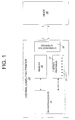
- a thermal label/tag printer 20 in accordance with the present invention includes a thermal printhead 22 for printing barcode and/or alpha-numeric data on a web of record members such as tags and labels.
- a microprocessor 24 controls the operation of the thermal printhead 22, which includes a plurality of printing elements 23, alternately referred to as dot elements. Specifically, the microprocessor 24 controls the printhead 22 to print data received from the host 28 and/or other input devices, not shown, such as a keyboard, barcode scanner, etc., in accordance with software stored in the memory 26.
- the memory 26 may include ROM and/or RAM, and/or a flash type memory, etc.
- the microprocessor 24 also monitors the condition of the thermal printhead to determine whether one or more printing elements 23 are likely to fail soon as discussed in detail below.
- the thermal label/tag printer 20 communicates with the host computer 28 via a communication interface 25 which may take the form of a hard-wired interface, such as a RS 232 interface, or a wireless interface, such as a radio frequency (RF) or infrared (IR) interface.
- a communication interface 25 may take the form of a hard-wired interface, such as a RS 232 interface, or a wireless interface, such as a radio frequency (RF) or infrared (IR) interface.
- RF radio frequency
- IR infrared
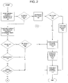
- the microprocessor 24 executes the thermal printhead failure prediction routine, depicted in Fig. 2, to predict wheather an inidividual printing element of the thermal printhead is failing.
- the routine is preferably executed to monitor each of the printing elements 23 of the printhead 22 by looping through the routine until all of the printing elements 23 are checked. Alternatively, it may be executed a single time to predict whether one printing element is failing, or it may be executed several times to test a subset of the printing elements 23 of the thermal printhead 22.
- the first printing element position is loaded prior to execution of the routine as depicted in Fig. 2. Alternately, if it is desired to only test a single printing element, that element position is loaded prior to execution. If it is desired to test a subset of the printing elements 23, the position of the first printing element of the subset is loaded prior to execution.
- the microprocessor 24 then begins the failure prediction routine by evaluating the loaded printing element or dot element of the thermal printhead 22. Specifically, the microprocessor 24 determines the current resistance value of the printing element at block 100 and stores this value for later use. At block 102, the microprocessor 24 determines whether the resistance of the printing element indicates that it has failed.
- the microprocessor 24 determines at block 102 that the printing element has not yet failed, the microprocessor 24 proceeds to block 104 where it compares a resistance value, or values, previously stored for that printing element to the current resistance that was found at block 100 to determine a resistive trend. If the microprocessor 24 determines at block 106 that the resistive trend of the printing element is increasing, the microprocessor 24 proceeds to block 108 to determine whether a characteristic of the increasing resistive trend has exceeded predetermined boundaries. This determination may be made by comparing the curve defined by the resistive trend for the printing element to a predetermined, previously stored curve to determine whether the printing element is approaching failure. The difference between the curve defined by the resistive trend and a predetermined curve can also be examined to determine whether the printing element is approaching failure.
- the average value and/or the maximum value and/or the minimum value of the difference between the curves may be compared to predetermined values to determine whether the printing element is approaching failure.
- this determination may be made by comparing the slope or rate of change of the resistive trend for the printing element to a predetermined slope or rate of change.
- the current resistance value of the printing element may also be used as the characteristic of the trend where the resistance is compared to a reference value to determine whether it is greater than the reference indicating approaching failure of the element.
- the microprocessor 24 predicts that the printing element is failing and proceeds to block 110.
- the microprocessor 24 stores in memory the position of the printing element predicted to fail.
- the microprocessor 24 then proceeds to block 124 to generate a warning message that preferably includes the identity of the printing element approaching failure and/or its position.
- the warning message may be sent to a host computer 28 via a communication interface 25 in the thermal label/tag printer 20.
- a warning indication may be directly displayed to the user of the thermal label/tag printer 20.
- a message may be displayed on a display of the thermal label/tag printer 20 or a warning LED on the thermal label/tag printer 20 may be illuminated.
- the next printing element position to be evaluated is then loaded by the microprocessor 24 in block 114. This allows all printing elements 23 of the thermal printhead 22 to be monitored when the routine is executed in a loop. If the routine is executing in a loop, the microprocessor 24 returns to block 100 to continue testing the remainder of the printing elements 23 of the thermal printhead 22.
- the microprocessor 24 determines in block 108 that the resistive trend does not exceed predetermined boundaries, the next printing element is loaded at block 114. If the routine is executing in a loop, the microprocessor 24 the returns to block 100.
- microprocessor 24 determines in block 106 that the resistive trend is not increasing, the microprocessor 24 proceeds to block 116 where it evaluates whether the resistive trend is decreasing. If the resistive trend is not decreasing, the next printing element is loaded at block 114. If the routine is executing in a loop, the microprocessor 24 then returns to block 100.
- the microprocessor 24 determines at block 116 that the resistive trend is decreasing, the microprocessor 24 then determines at block 118 whether a characteristic of the decreasing resistive trend has exceeded predetermined boundaries in a manner similar to that described with reference to block 108. If a characteristic of the resistive trend exceeds predetermined boundaries, the microprocessor 24 proceeds to block 110 and stores the position of the predicted failing printing element in memory 26. At block 110, the microprocessor 24 also stores selected characteristics of the resistive trend. The microprocessor 24 then proceeds to block 124 to generate a warning message indicating the printing element approaching failure and/or its position.
- the warning message may be sent to a host computer 28 via a communication interface 25 and/or a warning indication, such as a message on a display screen of the thermal label/tag printer 20 or an illuminated LED on the thermal label/tag printer 20, may be displayed.
- a warning indication such as a message on a display screen of the thermal label/tag printer 20 or an illuminated LED on the thermal label/tag printer 20, may be displayed.
- the next printing element position is then loaded by the microprocessor 24 at block 114. If the routine is executing in a loop, the microprocessor 24 returns to block 100 to continue testing the remainder of the printing elements 23 of the thermal printhead 22.
- microprocessor 24 determines at block 118 that the downward resistive trend has not exceeded predefined boundaries, the microprocessor 24 proceeds from block 118 to block 114 and loads the position of the next printing element to be evaluated at block 114, thereafter returning to block 100 if the routine is executing in a loop.
- the microprocessor 24 determines that the loaded printing element has failed, the microprocessor 24 proceeds to block 120 where it increments a variable or register to indicate that it has detected another failed printing element. This variable or register may be stored in memory 26. The microprocessor 24 then proceeds to block 122 where it evaluates whether three or more failed printing elements 23 have been detected yet by checking the variable or register recording the number of failed printing elements 23. If three or more printing elements 23 in the thermal printhead 22 have failed, the microprocessor 24 proceeds to block 110 where the position of the failed printing element is stored in memory 26 along with an indication that the element has failed. The microprocessor 24 then proceeds to block 124 where a warning message is generated indicating that the thermal printhead 22 has failed.
- the warning message may be sent to a host computer 28 via a communication interface 25 and/or a warning indication may be directly displayed to the user of the thermal label/tag printer 20.
- the microprocessor 24 then loads the position of the next printing element to be evaluated at block 114. If the routine is executing in a loop, the microprocessor 24 returns thereafter to block 100.
- data to be printed may be shifted around one or two failed printing elements 23 and still be printed with acceptable results.
- the microprocessor 24 at block 126 performs a known data dot shift routine to shift data to be printed around the failed printing element. Thereafter the microprocessor 24 proceeds from block 126 to block 114 where the microprocessor 24 loads the position of the next printing element to be evaluated. If the routine is executing in a loop, the microprocessor 24 returns to block 100.
Landscapes
- Physics & Mathematics (AREA)
- General Physics & Mathematics (AREA)
- Engineering & Computer Science (AREA)
- Theoretical Computer Science (AREA)
- Accessory Devices And Overall Control Thereof (AREA)
Abstract
Description
Claims (10)
- In a barcode printer, a system to predict thermal printhead failure comprising:a thermal printhead including a plurality of printing elements, each printing element having an associated resistance value; anda processor for sampling over time a plurality of resistance values for at least one of said printing elements and for comparing each sampled resistance value to its immediately preceding sampled resistance value for that printing element to determine a trend of the resistance of at least one of said printing elements, said processor generating a warning for indicating when a characteristic of the resistive trend deviates beyond a predetermined boundary.
- The barcode printer as defined in claim 1, wherein said characteristic of said resistive trend exceeds a predetermined boundary when the rate of increase in the resistive trend exceeds a predetermined value.
- The barcode printer as defined in claim 1, wherein said characteristic of said resistive trend exceeds a predetermined boundary when the rate of decrease in the resistive trend exceeds a predetermined value.
- In a printer for printing on a web of record members, a system for detecting thermal printhead failure comprising:a thermal printhead including a plurality of printing elements each having an associated resistance;a processor for sampling the resistance of a plurality of said printing elements over time to determine an associated resistive trend for each of said plurality of printing elements by comparing each resistance sampled for a given printing element to its immediately preceding sampled resistance for said given printing element, said processor determining whether the resistive trend of each printing element exceeds a predetermined limit; anda read/write memory for storing the position of a printing element determined to have a resistive trend that exceeds a predetermined limit.
- The printer for printing on a web of record members as defined in claim 4, wherein said resistive trend exceeds said predetermined limit when the rate of increase in the resistive trend exceeds a predetermined value.
- The printer for printing on a web of record members as defined in claim 4, wherein said resistive trend exceeds said predetermined limit when the rate of decrease in the resistive trend exceeds a predetermined value.
- The printer for printing on a web of record members as defined in claim 4, wherein said microprocessor determines whether said resistive trend of one of said printing elements exceeds said predetermined limit by comparing said resistive trend of one of said printing elements to a predetermined curve.
- A method of monitoring a thermal printer having a thermal printhead comprising a plurality of printing elements, a processing means, and a memory for storing data, comprising:sampling over time a plurality of resistance values for at least one of said printing elements;storing said sampled resistance values;comparing each of said resistance values sampled for a print element to its immediately preceding sampled resistance value for the print element to determine a trend;comparing a characteristic of said resistance trend to a reference;storing the printing element position in said memory when said characteristic of said resistance trend exceeds said reference; andgenerating a warning when said characteristic of said resistance trend exceeds said reference.
- The method of monitoring a thermal printer as recited in claim 8 including the step of sending said warning to a host computer.
- A method of monitoring a label printer having a thermal printhead including a plurality of printing elements, a processing means, and a memory comprising:sampling over time a plurality of resistance values for at least one of said printing elements;storing said sampled resistance values;comparing each of said resistance values sampled for a print element to its immediately preceding sampled resistance value for the print element to determine a trend;determining if said resistance trend is increasing or decreasing;comparing a characteristic of said resistance trend to a first reference when said resistance trend is increasing to determine if an upper limit is exceeded;comparing a characteristic of said resistance trend to a second reference when said resistance trend is decreasing to determine if said characteristic falls below a lower limit; andgenerating a warning when either said upper limit is exceeded by said characteristic or said characteristic is below said lower limit.
Applications Claiming Priority (2)
| Application Number | Priority Date | Filing Date | Title |
|---|---|---|---|
| US92985297A | 1997-09-15 | 1997-09-15 | |
| US929852 | 1997-09-15 |
Publications (3)
| Publication Number | Publication Date |
|---|---|
| EP0902385A2 true EP0902385A2 (en) | 1999-03-17 |
| EP0902385A3 EP0902385A3 (en) | 2002-01-09 |
| EP0902385B1 EP0902385B1 (en) | 2005-09-14 |
Family
ID=25458559
Family Applications (1)
| Application Number | Title | Priority Date | Filing Date |
|---|---|---|---|
| EP98115925A Expired - Lifetime EP0902385B1 (en) | 1997-09-15 | 1998-08-24 | Early thermal printhead failure prediction system |
Country Status (5)
| Country | Link |
|---|---|
| US (1) | US6188423B1 (en) |
| EP (1) | EP0902385B1 (en) |
| JP (1) | JPH11138882A (en) |
| CA (1) | CA2242500C (en) |
| DE (1) | DE69831539T2 (en) |
Cited By (2)
| Publication number | Priority date | Publication date | Assignee | Title |
|---|---|---|---|---|
| WO2001058693A1 (en) * | 2000-02-08 | 2001-08-16 | Avery Berkel Limited | Thermal printhead operation |
| WO2005022930A1 (en) * | 2003-08-25 | 2005-03-10 | Spx Corporation | Apparatus and method for monitoring transmission systems using embedded test signals |
Families Citing this family (25)
| Publication number | Priority date | Publication date | Assignee | Title |
|---|---|---|---|---|
| US6724895B1 (en) | 1998-06-18 | 2004-04-20 | Supersensor (Proprietary) Limited | Electronic identification system and method with source authenticity verification |
| US6336083B1 (en) * | 1999-05-21 | 2002-01-01 | Watlow Electric Manufacturing Company | Method and apparatus for predicting heater failure |
| US7213048B1 (en) * | 2000-04-05 | 2007-05-01 | Microsoft Corporation | Context aware computing devices and methods |
| US7137000B2 (en) * | 2001-08-24 | 2006-11-14 | Zih Corp. | Method and apparatus for article authentication |
| US20030061947A1 (en) * | 2001-10-01 | 2003-04-03 | Hohberger Clive P. | Method and apparatus for associating on demand certain selected media and value-adding elements |
| US6969134B2 (en) * | 2001-10-01 | 2005-11-29 | Zih Corp. | Printer or other media processor with on-demand selective media converter |
| US6714893B2 (en) | 2002-02-15 | 2004-03-30 | International Business Machines Corporation | Enhanced concern indicator failure prediction system |
| US20040017578A1 (en) * | 2002-07-25 | 2004-01-29 | Gallant John M. | Method of detecting bad dots in print zone |
| US7293042B2 (en) * | 2003-05-12 | 2007-11-06 | Sun Microsystems, Inc. | Managing and predicting component failure based on pattern recognition of subcomponent exposure to failure |
| US7047160B2 (en) * | 2004-06-09 | 2006-05-16 | Polaroid Corporation | System and method for determining maintenance needs of complex electromechanical systems |
| US9296214B2 (en) | 2004-07-02 | 2016-03-29 | Zih Corp. | Thermal print head usage monitor and method for using the monitor |
| US7372475B2 (en) * | 2005-03-09 | 2008-05-13 | Datamax Corporation | System and method for thermal transfer print head profiling |
| US8330965B2 (en) * | 2006-04-13 | 2012-12-11 | Xerox Corporation | Marking engine selection |
| US10914777B2 (en) | 2017-03-24 | 2021-02-09 | Rosemount Aerospace Inc. | Probe heater remaining useful life determination |
| US10895592B2 (en) | 2017-03-24 | 2021-01-19 | Rosemount Aerospace Inc. | Probe heater remaining useful life determination |
| US11060992B2 (en) | 2017-03-24 | 2021-07-13 | Rosemount Aerospace Inc. | Probe heater remaining useful life determination |
| JP2019084799A (en) | 2017-11-10 | 2019-06-06 | セイコーエプソン株式会社 | Thermal printer, control method of thermal printer, and printing system |
| US11061080B2 (en) | 2018-12-14 | 2021-07-13 | Rosemount Aerospace Inc. | Real time operational leakage current measurement for probe heater PHM and prediction of remaining useful life |
| US10962580B2 (en) | 2018-12-14 | 2021-03-30 | Rosemount Aerospace Inc. | Electric arc detection for probe heater PHM and prediction of remaining useful life |
| US11639954B2 (en) | 2019-05-29 | 2023-05-02 | Rosemount Aerospace Inc. | Differential leakage current measurement for heater health monitoring |
| US11472562B2 (en) | 2019-06-14 | 2022-10-18 | Rosemount Aerospace Inc. | Health monitoring of an electrical heater of an air data probe |
| US11930563B2 (en) | 2019-09-16 | 2024-03-12 | Rosemount Aerospace Inc. | Monitoring and extending heater life through power supply polarity switching |
| US11293995B2 (en) | 2020-03-23 | 2022-04-05 | Rosemount Aerospace Inc. | Differential leakage current measurement for heater health monitoring |
| US11630140B2 (en) | 2020-04-22 | 2023-04-18 | Rosemount Aerospace Inc. | Prognostic health monitoring for heater |
| US11623456B2 (en) | 2020-08-05 | 2023-04-11 | Illinois Tool Works Inc. | Label printer with barcode shifting and scale incorporating such a label printer |
Family Cites Families (4)
| Publication number | Priority date | Publication date | Assignee | Title |
|---|---|---|---|---|
| US4595935A (en) * | 1984-08-14 | 1986-06-17 | Ncr Canada Ltd. | System for detecting defective thermal printhead elements |
| JPH0630888B2 (en) * | 1985-08-29 | 1994-04-27 | 株式会社サト− | Heater circuit defect detection device for thermal print head |
| JPS6262776A (en) * | 1985-09-14 | 1987-03-19 | Sato :Kk | Thermal printing head heating circuit defect detection device |
| US4996487A (en) * | 1989-04-24 | 1991-02-26 | International Business Machines Corporation | Apparatus for detecting failure of thermal heaters in ink jet printers |
-
1998
- 1998-08-19 CA CA002242500A patent/CA2242500C/en not_active Expired - Lifetime
- 1998-08-24 EP EP98115925A patent/EP0902385B1/en not_active Expired - Lifetime
- 1998-08-24 DE DE69831539T patent/DE69831539T2/en not_active Expired - Lifetime
- 1998-09-08 JP JP10253599A patent/JPH11138882A/en active Pending
-
1999
- 1999-11-08 US US09/435,969 patent/US6188423B1/en not_active Expired - Lifetime
Cited By (4)
| Publication number | Priority date | Publication date | Assignee | Title |
|---|---|---|---|---|
| WO2001058693A1 (en) * | 2000-02-08 | 2001-08-16 | Avery Berkel Limited | Thermal printhead operation |
| US6846055B2 (en) | 2000-02-08 | 2005-01-25 | Avery Berkel Limited | Thermal printhead operation |
| WO2005022930A1 (en) * | 2003-08-25 | 2005-03-10 | Spx Corporation | Apparatus and method for monitoring transmission systems using embedded test signals |
| US7298396B2 (en) | 2003-08-25 | 2007-11-20 | Spx Corporation | Apparatus and method for monitoring transmission systems using embedded test signals |
Also Published As
| Publication number | Publication date |
|---|---|
| CA2242500A1 (en) | 1999-03-15 |
| CA2242500C (en) | 2007-11-13 |
| EP0902385B1 (en) | 2005-09-14 |
| EP0902385A3 (en) | 2002-01-09 |
| DE69831539T2 (en) | 2006-06-14 |
| US6188423B1 (en) | 2001-02-13 |
| DE69831539D1 (en) | 2005-10-20 |
| JPH11138882A (en) | 1999-05-25 |
Similar Documents
| Publication | Publication Date | Title |
|---|---|---|
| US6188423B1 (en) | Early thermal printhead failure prediction system | |
| JP6774636B2 (en) | Abnormality analysis methods, programs and systems | |
| US5488223A (en) | System and method for automatic selection of printer control parameters | |
| EP1811354A1 (en) | Plant monitoring apparatus and plant monitoring method | |
| US20240402961A1 (en) | Dynamic Configuration of a Printer for a Printing Operation | |
| CN117707444B (en) | A cloud printer abnormal state identification and maintenance management system | |
| US8386730B2 (en) | Data logger, data saving method and program | |
| US20240231714A1 (en) | Utilization of a Printhead Resistance Sensor and a Model to Determine a Printer Status | |
| CN101807164B (en) | Monitoring arrangement, information processing system are unified supervision method | |
| US20050096877A1 (en) | System and method for determination of load monitoring condition and load monitoring program | |
| US7085681B1 (en) | Symbiotic interrupt/polling approach for monitoring physical sensors | |
| CN118514446B (en) | Black mark optimization detection method and device | |
| US9815297B2 (en) | Printing device, control method, and printing system | |
| JP2000137758A (en) | Product management method and its implementation device | |
| US5452958A (en) | Drive coil protection apparatus and method and printer incorporating the apparatus | |
| JP5648314B2 (en) | Failure related item setting device, program, and failure prediction system | |
| US20120101669A1 (en) | Sail Usage Sensing System and Method | |
| US20040017578A1 (en) | Method of detecting bad dots in print zone | |
| US10679149B1 (en) | Predictive terminal management | |
| EP4503440A1 (en) | System and method for verifying operational integrity of a control head monitor | |
| US20070133046A1 (en) | Printing Program, Printing Method, and Host Apparatus | |
| CN120096214A (en) | Incubator data printing system, incubator data printing method and related equipment | |
| KR20230120763A (en) | System for artificial intelligence-based detection of abnormal signs of cargo anchorage devices and industrial structure safety abnormalities pre-prediction and method thereof | |
| JPH10198884A (en) | Transmitter with error output function | |
| CN114118201A (en) | Medical equipment performance index detection method and device based on active learning |
Legal Events
| Date | Code | Title | Description |
|---|---|---|---|
| PUAI | Public reference made under article 153(3) epc to a published international application that has entered the european phase |
Free format text: ORIGINAL CODE: 0009012 |
|
| AK | Designated contracting states |
Kind code of ref document: A2 Designated state(s): AT BE CH CY DE DK ES FI FR GB GR IE IT LI LU MC NL PT SE Kind code of ref document: A2 Designated state(s): DE FR GB NL |
|
| AX | Request for extension of the european patent |
Free format text: AL;LT;LV;MK;RO;SI |
|
| PUAL | Search report despatched |
Free format text: ORIGINAL CODE: 0009013 |
|
| AK | Designated contracting states |
Kind code of ref document: A3 Designated state(s): AT BE CH CY DE DK ES FI FR GB GR IE IT LI LU MC NL PT SE |
|
| AX | Request for extension of the european patent |
Free format text: AL;LT;LV;MK;RO;SI |
|
| RIC1 | Information provided on ipc code assigned before grant |
Free format text: 7G 06K 1/12 A, 7G 06K 15/02 B, 7B 41J 2/35 B |
|
| 17P | Request for examination filed |
Effective date: 20020701 |
|
| AKX | Designation fees paid |
Free format text: DE FR GB NL |
|
| RAP1 | Party data changed (applicant data changed or rights of an application transferred) |
Owner name: PAXAR AMERICAS, INC. |
|
| 17Q | First examination report despatched |
Effective date: 20040716 |
|
| GRAP | Despatch of communication of intention to grant a patent |
Free format text: ORIGINAL CODE: EPIDOSNIGR1 |
|
| GRAS | Grant fee paid |
Free format text: ORIGINAL CODE: EPIDOSNIGR3 |
|
| GRAA | (expected) grant |
Free format text: ORIGINAL CODE: 0009210 |
|
| AK | Designated contracting states |
Kind code of ref document: B1 Designated state(s): DE FR GB NL |
|
| REG | Reference to a national code |
Ref country code: GB Ref legal event code: FG4D |
|
| REF | Corresponds to: |
Ref document number: 69831539 Country of ref document: DE Date of ref document: 20051020 Kind code of ref document: P |
|
| ET | Fr: translation filed | ||
| PLBE | No opposition filed within time limit |
Free format text: ORIGINAL CODE: 0009261 |
|
| STAA | Information on the status of an ep patent application or granted ep patent |
Free format text: STATUS: NO OPPOSITION FILED WITHIN TIME LIMIT |
|
| 26N | No opposition filed |
Effective date: 20060615 |
|
| PGFP | Annual fee paid to national office [announced via postgrant information from national office to epo] |
Ref country code: NL Payment date: 20080824 Year of fee payment: 11 |
|
| REG | Reference to a national code |
Ref country code: NL Ref legal event code: V1 Effective date: 20100301 |
|
| PG25 | Lapsed in a contracting state [announced via postgrant information from national office to epo] |
Ref country code: NL Free format text: LAPSE BECAUSE OF NON-PAYMENT OF DUE FEES Effective date: 20100301 |
|
| REG | Reference to a national code |
Ref country code: FR Ref legal event code: PLFP Year of fee payment: 19 |
|
| REG | Reference to a national code |
Ref country code: FR Ref legal event code: PLFP Year of fee payment: 20 |
|
| PGFP | Annual fee paid to national office [announced via postgrant information from national office to epo] |
Ref country code: GB Payment date: 20170725 Year of fee payment: 20 Ref country code: DE Payment date: 20170825 Year of fee payment: 20 Ref country code: FR Payment date: 20170720 Year of fee payment: 20 |
|
| REG | Reference to a national code |
Ref country code: DE Ref legal event code: R071 Ref document number: 69831539 Country of ref document: DE |
|
| REG | Reference to a national code |
Ref country code: GB Ref legal event code: PE20 Expiry date: 20180823 |
|
| PG25 | Lapsed in a contracting state [announced via postgrant information from national office to epo] |
Ref country code: GB Free format text: LAPSE BECAUSE OF EXPIRATION OF PROTECTION Effective date: 20180823 |