EP0902348A2 - Battery rental apparatus - Google Patents
Battery rental apparatus Download PDFInfo
- Publication number
- EP0902348A2 EP0902348A2 EP98116854A EP98116854A EP0902348A2 EP 0902348 A2 EP0902348 A2 EP 0902348A2 EP 98116854 A EP98116854 A EP 98116854A EP 98116854 A EP98116854 A EP 98116854A EP 0902348 A2 EP0902348 A2 EP 0902348A2
- Authority
- EP
- European Patent Office
- Prior art keywords
- temperature
- battery
- section
- preservation
- rental apparatus
- Prior art date
- Legal status (The legal status is an assumption and is not a legal conclusion. Google has not performed a legal analysis and makes no representation as to the accuracy of the status listed.)
- Granted
Links
- 230000004308 accommodation Effects 0.000 claims abstract description 42
- 238000004321 preservation Methods 0.000 claims abstract description 40
- 238000009423 ventilation Methods 0.000 claims description 13
- 230000007274 generation of a signal involved in cell-cell signaling Effects 0.000 claims description 7
- 239000011810 insulating material Substances 0.000 claims description 5
- 238000012545 processing Methods 0.000 description 6
- 238000004891 communication Methods 0.000 description 4
- 230000004044 response Effects 0.000 description 3
- 230000003466 anti-cipated effect Effects 0.000 description 2
- 238000010586 diagram Methods 0.000 description 2
- 238000007599 discharging Methods 0.000 description 2
- 230000007613 environmental effect Effects 0.000 description 2
- 238000002955 isolation Methods 0.000 description 2
- 238000004519 manufacturing process Methods 0.000 description 2
- 238000005259 measurement Methods 0.000 description 2
- 239000005862 Whey Substances 0.000 description 1
- 102000007544 Whey Proteins Human genes 0.000 description 1
- 108010046377 Whey Proteins Proteins 0.000 description 1
- 239000003795 chemical substances by application Substances 0.000 description 1
- 238000010276 construction Methods 0.000 description 1
- 238000001514 detection method Methods 0.000 description 1
- 230000006866 deterioration Effects 0.000 description 1
- 230000000694 effects Effects 0.000 description 1
- 230000005611 electricity Effects 0.000 description 1
- 238000005286 illumination Methods 0.000 description 1
- 238000003780 insertion Methods 0.000 description 1
- 230000037431 insertion Effects 0.000 description 1
- 238000009434 installation Methods 0.000 description 1
- 239000002184 metal Substances 0.000 description 1
- 238000000034 method Methods 0.000 description 1
- 238000003672 processing method Methods 0.000 description 1
- 230000006641 stabilisation Effects 0.000 description 1
Images


Classifications
-
- G—PHYSICS
- G05—CONTROLLING; REGULATING
- G05D—SYSTEMS FOR CONTROLLING OR REGULATING NON-ELECTRIC VARIABLES
- G05D23/00—Control of temperature
- G05D23/19—Control of temperature characterised by the use of electric means
- G05D23/1906—Control of temperature characterised by the use of electric means using an analogue comparing device
-
- B—PERFORMING OPERATIONS; TRANSPORTING
- B60—VEHICLES IN GENERAL
- B60L—PROPULSION OF ELECTRICALLY-PROPELLED VEHICLES; SUPPLYING ELECTRIC POWER FOR AUXILIARY EQUIPMENT OF ELECTRICALLY-PROPELLED VEHICLES; ELECTRODYNAMIC BRAKE SYSTEMS FOR VEHICLES IN GENERAL; MAGNETIC SUSPENSION OR LEVITATION FOR VEHICLES; MONITORING OPERATING VARIABLES OF ELECTRICALLY-PROPELLED VEHICLES; ELECTRIC SAFETY DEVICES FOR ELECTRICALLY-PROPELLED VEHICLES
- B60L53/00—Methods of charging batteries, specially adapted for electric vehicles; Charging stations or on-board charging equipment therefor; Exchange of energy storage elements in electric vehicles
- B60L53/30—Constructional details of charging stations
- B60L53/305—Communication interfaces
-
- B—PERFORMING OPERATIONS; TRANSPORTING
- B60—VEHICLES IN GENERAL
- B60L—PROPULSION OF ELECTRICALLY-PROPELLED VEHICLES; SUPPLYING ELECTRIC POWER FOR AUXILIARY EQUIPMENT OF ELECTRICALLY-PROPELLED VEHICLES; ELECTRODYNAMIC BRAKE SYSTEMS FOR VEHICLES IN GENERAL; MAGNETIC SUSPENSION OR LEVITATION FOR VEHICLES; MONITORING OPERATING VARIABLES OF ELECTRICALLY-PROPELLED VEHICLES; ELECTRIC SAFETY DEVICES FOR ELECTRICALLY-PROPELLED VEHICLES
- B60L53/00—Methods of charging batteries, specially adapted for electric vehicles; Charging stations or on-board charging equipment therefor; Exchange of energy storage elements in electric vehicles
- B60L53/60—Monitoring or controlling charging stations
- B60L53/65—Monitoring or controlling charging stations involving identification of vehicles or their battery types
-
- B—PERFORMING OPERATIONS; TRANSPORTING
- B60—VEHICLES IN GENERAL
- B60L—PROPULSION OF ELECTRICALLY-PROPELLED VEHICLES; SUPPLYING ELECTRIC POWER FOR AUXILIARY EQUIPMENT OF ELECTRICALLY-PROPELLED VEHICLES; ELECTRODYNAMIC BRAKE SYSTEMS FOR VEHICLES IN GENERAL; MAGNETIC SUSPENSION OR LEVITATION FOR VEHICLES; MONITORING OPERATING VARIABLES OF ELECTRICALLY-PROPELLED VEHICLES; ELECTRIC SAFETY DEVICES FOR ELECTRICALLY-PROPELLED VEHICLES
- B60L53/00—Methods of charging batteries, specially adapted for electric vehicles; Charging stations or on-board charging equipment therefor; Exchange of energy storage elements in electric vehicles
- B60L53/80—Exchanging energy storage elements, e.g. removable batteries
-
- B—PERFORMING OPERATIONS; TRANSPORTING
- B60—VEHICLES IN GENERAL
- B60L—PROPULSION OF ELECTRICALLY-PROPELLED VEHICLES; SUPPLYING ELECTRIC POWER FOR AUXILIARY EQUIPMENT OF ELECTRICALLY-PROPELLED VEHICLES; ELECTRODYNAMIC BRAKE SYSTEMS FOR VEHICLES IN GENERAL; MAGNETIC SUSPENSION OR LEVITATION FOR VEHICLES; MONITORING OPERATING VARIABLES OF ELECTRICALLY-PROPELLED VEHICLES; ELECTRIC SAFETY DEVICES FOR ELECTRICALLY-PROPELLED VEHICLES
- B60L58/00—Methods or circuit arrangements for monitoring or controlling batteries or fuel cells, specially adapted for electric vehicles
- B60L58/10—Methods or circuit arrangements for monitoring or controlling batteries or fuel cells, specially adapted for electric vehicles for monitoring or controlling batteries
- B60L58/24—Methods or circuit arrangements for monitoring or controlling batteries or fuel cells, specially adapted for electric vehicles for monitoring or controlling batteries for controlling the temperature of batteries
- B60L58/25—Methods or circuit arrangements for monitoring or controlling batteries or fuel cells, specially adapted for electric vehicles for monitoring or controlling batteries for controlling the temperature of batteries by controlling the electric load
-
- H—ELECTRICITY
- H01—ELECTRIC ELEMENTS
- H01M—PROCESSES OR MEANS, e.g. BATTERIES, FOR THE DIRECT CONVERSION OF CHEMICAL ENERGY INTO ELECTRICAL ENERGY
- H01M10/00—Secondary cells; Manufacture thereof
- H01M10/42—Methods or arrangements for servicing or maintenance of secondary cells or secondary half-cells
- H01M10/48—Accumulators combined with arrangements for measuring, testing or indicating the condition of cells, e.g. the level or density of the electrolyte
- H01M10/486—Accumulators combined with arrangements for measuring, testing or indicating the condition of cells, e.g. the level or density of the electrolyte for measuring temperature
-
- H—ELECTRICITY
- H01—ELECTRIC ELEMENTS
- H01M—PROCESSES OR MEANS, e.g. BATTERIES, FOR THE DIRECT CONVERSION OF CHEMICAL ENERGY INTO ELECTRICAL ENERGY
- H01M10/00—Secondary cells; Manufacture thereof
- H01M10/60—Heating or cooling; Temperature control
- H01M10/61—Types of temperature control
- H01M10/613—Cooling or keeping cold
-
- H—ELECTRICITY
- H01—ELECTRIC ELEMENTS
- H01M—PROCESSES OR MEANS, e.g. BATTERIES, FOR THE DIRECT CONVERSION OF CHEMICAL ENERGY INTO ELECTRICAL ENERGY
- H01M10/00—Secondary cells; Manufacture thereof
- H01M10/60—Heating or cooling; Temperature control
- H01M10/61—Types of temperature control
- H01M10/615—Heating or keeping warm
-
- H—ELECTRICITY
- H01—ELECTRIC ELEMENTS
- H01M—PROCESSES OR MEANS, e.g. BATTERIES, FOR THE DIRECT CONVERSION OF CHEMICAL ENERGY INTO ELECTRICAL ENERGY
- H01M10/00—Secondary cells; Manufacture thereof
- H01M10/60—Heating or cooling; Temperature control
- H01M10/62—Heating or cooling; Temperature control specially adapted for specific applications
- H01M10/625—Vehicles
-
- H—ELECTRICITY
- H01—ELECTRIC ELEMENTS
- H01M—PROCESSES OR MEANS, e.g. BATTERIES, FOR THE DIRECT CONVERSION OF CHEMICAL ENERGY INTO ELECTRICAL ENERGY
- H01M10/00—Secondary cells; Manufacture thereof
- H01M10/60—Heating or cooling; Temperature control
- H01M10/63—Control systems
- H01M10/633—Control systems characterised by algorithms, flow charts, software details or the like
-
- H—ELECTRICITY
- H01—ELECTRIC ELEMENTS
- H01M—PROCESSES OR MEANS, e.g. BATTERIES, FOR THE DIRECT CONVERSION OF CHEMICAL ENERGY INTO ELECTRICAL ENERGY
- H01M10/00—Secondary cells; Manufacture thereof
- H01M10/60—Heating or cooling; Temperature control
- H01M10/63—Control systems
- H01M10/635—Control systems based on ambient temperature
-
- H—ELECTRICITY
- H01—ELECTRIC ELEMENTS
- H01M—PROCESSES OR MEANS, e.g. BATTERIES, FOR THE DIRECT CONVERSION OF CHEMICAL ENERGY INTO ELECTRICAL ENERGY
- H01M10/00—Secondary cells; Manufacture thereof
- H01M10/60—Heating or cooling; Temperature control
- H01M10/65—Means for temperature control structurally associated with the cells
- H01M10/656—Means for temperature control structurally associated with the cells characterised by the type of heat-exchange fluid
- H01M10/6561—Gases
- H01M10/6563—Gases with forced flow, e.g. by blowers
-
- H—ELECTRICITY
- H01—ELECTRIC ELEMENTS
- H01M—PROCESSES OR MEANS, e.g. BATTERIES, FOR THE DIRECT CONVERSION OF CHEMICAL ENERGY INTO ELECTRICAL ENERGY
- H01M10/00—Secondary cells; Manufacture thereof
- H01M10/60—Heating or cooling; Temperature control
- H01M10/65—Means for temperature control structurally associated with the cells
- H01M10/658—Means for temperature control structurally associated with the cells by thermal insulation or shielding
-
- Y—GENERAL TAGGING OF NEW TECHNOLOGICAL DEVELOPMENTS; GENERAL TAGGING OF CROSS-SECTIONAL TECHNOLOGIES SPANNING OVER SEVERAL SECTIONS OF THE IPC; TECHNICAL SUBJECTS COVERED BY FORMER USPC CROSS-REFERENCE ART COLLECTIONS [XRACs] AND DIGESTS
- Y02—TECHNOLOGIES OR APPLICATIONS FOR MITIGATION OR ADAPTATION AGAINST CLIMATE CHANGE
- Y02E—REDUCTION OF GREENHOUSE GAS [GHG] EMISSIONS, RELATED TO ENERGY GENERATION, TRANSMISSION OR DISTRIBUTION
- Y02E60/00—Enabling technologies; Technologies with a potential or indirect contribution to GHG emissions mitigation
- Y02E60/10—Energy storage using batteries
-
- Y—GENERAL TAGGING OF NEW TECHNOLOGICAL DEVELOPMENTS; GENERAL TAGGING OF CROSS-SECTIONAL TECHNOLOGIES SPANNING OVER SEVERAL SECTIONS OF THE IPC; TECHNICAL SUBJECTS COVERED BY FORMER USPC CROSS-REFERENCE ART COLLECTIONS [XRACs] AND DIGESTS
- Y02—TECHNOLOGIES OR APPLICATIONS FOR MITIGATION OR ADAPTATION AGAINST CLIMATE CHANGE
- Y02T—CLIMATE CHANGE MITIGATION TECHNOLOGIES RELATED TO TRANSPORTATION
- Y02T10/00—Road transport of goods or passengers
- Y02T10/60—Other road transportation technologies with climate change mitigation effect
- Y02T10/70—Energy storage systems for electromobility, e.g. batteries
-
- Y—GENERAL TAGGING OF NEW TECHNOLOGICAL DEVELOPMENTS; GENERAL TAGGING OF CROSS-SECTIONAL TECHNOLOGIES SPANNING OVER SEVERAL SECTIONS OF THE IPC; TECHNICAL SUBJECTS COVERED BY FORMER USPC CROSS-REFERENCE ART COLLECTIONS [XRACs] AND DIGESTS
- Y02—TECHNOLOGIES OR APPLICATIONS FOR MITIGATION OR ADAPTATION AGAINST CLIMATE CHANGE
- Y02T—CLIMATE CHANGE MITIGATION TECHNOLOGIES RELATED TO TRANSPORTATION
- Y02T10/00—Road transport of goods or passengers
- Y02T10/60—Other road transportation technologies with climate change mitigation effect
- Y02T10/7072—Electromobility specific charging systems or methods for batteries, ultracapacitors, supercapacitors or double-layer capacitors
-
- Y—GENERAL TAGGING OF NEW TECHNOLOGICAL DEVELOPMENTS; GENERAL TAGGING OF CROSS-SECTIONAL TECHNOLOGIES SPANNING OVER SEVERAL SECTIONS OF THE IPC; TECHNICAL SUBJECTS COVERED BY FORMER USPC CROSS-REFERENCE ART COLLECTIONS [XRACs] AND DIGESTS
- Y02—TECHNOLOGIES OR APPLICATIONS FOR MITIGATION OR ADAPTATION AGAINST CLIMATE CHANGE
- Y02T—CLIMATE CHANGE MITIGATION TECHNOLOGIES RELATED TO TRANSPORTATION
- Y02T90/00—Enabling technologies or technologies with a potential or indirect contribution to GHG emissions mitigation
- Y02T90/10—Technologies relating to charging of electric vehicles
- Y02T90/12—Electric charging stations
-
- Y—GENERAL TAGGING OF NEW TECHNOLOGICAL DEVELOPMENTS; GENERAL TAGGING OF CROSS-SECTIONAL TECHNOLOGIES SPANNING OVER SEVERAL SECTIONS OF THE IPC; TECHNICAL SUBJECTS COVERED BY FORMER USPC CROSS-REFERENCE ART COLLECTIONS [XRACs] AND DIGESTS
- Y02—TECHNOLOGIES OR APPLICATIONS FOR MITIGATION OR ADAPTATION AGAINST CLIMATE CHANGE
- Y02T—CLIMATE CHANGE MITIGATION TECHNOLOGIES RELATED TO TRANSPORTATION
- Y02T90/00—Enabling technologies or technologies with a potential or indirect contribution to GHG emissions mitigation
- Y02T90/10—Technologies relating to charging of electric vehicles
- Y02T90/16—Information or communication technologies improving the operation of electric vehicles
- Y02T90/167—Systems integrating technologies related to power network operation and communication or information technologies for supporting the interoperability of electric or hybrid vehicles, i.e. smartgrids as interface for battery charging of electric vehicles [EV] or hybrid vehicles [HEV]
-
- Y—GENERAL TAGGING OF NEW TECHNOLOGICAL DEVELOPMENTS; GENERAL TAGGING OF CROSS-SECTIONAL TECHNOLOGIES SPANNING OVER SEVERAL SECTIONS OF THE IPC; TECHNICAL SUBJECTS COVERED BY FORMER USPC CROSS-REFERENCE ART COLLECTIONS [XRACs] AND DIGESTS
- Y04—INFORMATION OR COMMUNICATION TECHNOLOGIES HAVING AN IMPACT ON OTHER TECHNOLOGY AREAS
- Y04S—SYSTEMS INTEGRATING TECHNOLOGIES RELATED TO POWER NETWORK OPERATION, COMMUNICATION OR INFORMATION TECHNOLOGIES FOR IMPROVING THE ELECTRICAL POWER GENERATION, TRANSMISSION, DISTRIBUTION, MANAGEMENT OR USAGE, i.e. SMART GRIDS
- Y04S30/00—Systems supporting specific end-user applications in the sector of transportation
- Y04S30/10—Systems supporting the interoperability of electric or hybrid vehicles
- Y04S30/14—Details associated with the interoperability, e.g. vehicle recognition, authentication, identification or billing
Definitions
- This invention relates to a battery rental apparatus for an electrically-operated vehicle, and more particularly to a battery rental apparatus which keeps the temperatures of a plurality of batteries accommodated in the apparatus to a preservation temperature for the batteries.
- a charging apparatus for a secondary battery which is constructed such that it accommodates and charges a plurality of secondary batteries for an electric automobile as disclosed in the official gazette of Japanese Patent Laid-Open Application No. Heisei 6-293251 is known.
- an isolation chamber for collecting and recovering or processing heat or gas generated during charging processing is provided at an uppermost portion of a support member on a tower of the apparatus and processing of heat generated when the secondary batteries are charged is performed.
- the charging apparatus of the official gazette of Japanese Patent Laid-Open Application No. Heisei 6-293251 is provided with an isolation chamber for collecting and recovering or processing heat or gas, it does not have means for keeping the secondary batteries to a predetermined preservation temperature against a variation of the ambient temperature or heat generated upon charging of the secondary batteries, and where the charging apparatus is installed outdoors, there is a subject that the temperature of the secondary batteries is excessively high or excessively low and this gives rise to deterioration of the performance of the secondary batteries and the efficiency in charging drops.
- a battery rental apparatus for an electrically-operated vehicle is supposed to be installed outdoors from a utilization object of the same, and temperature control is demanded particularly since it is exposed to a high temperature environment under the direct rays of the sun or to a low temperature environment in the winter.
- the battery rental apparatus In order to avoid such severe environmental (temperature) conditions, the battery rental apparatus should be arranged indoors. However, where it is arranged indoors, there is a limitation to the location of a battery rental apparatus and to the number of battery rental apparatus to be installed, and there is a subject that the convenience for a user is deteriorated.
- This invention has been made to solve such subjects as described above, and it is an object of the present invention to provide a battery rental apparatus superior in convenience which can keep the preservation temperature of a battery within a fixed temperature range and can be installed at any place.
- a battery rental apparatus which includes a battery accommodation section for accommodating therein a plurality of removable batteries to be carried on an electrically-operated vehicle and which recovers a battery to be returned from a user and lends a battery charged already is characterized in that it comprises temperature control means for keeping the battery accommodation section within a predetermined temperature range.
- the battery rental apparatus comprises temperature control means for keeping the battery accommodation section within the predetermined temperature range, even if it is installed outdoors where the temperature environmental condition is severe, it can maintain the performance of the batteries optimally.
- the battery rental apparatus is characterized in that the temperature control means includes a temperature preservation section which wraps the battery accommodation section, at least one sensor provided in the battery accommodation section or at least one external air temperature sensor provided outside the apparatus, a temperature regulator for varying the temperature of the temperature preservation section based on a temperature signal from the temperature sensor, and a temperature control section for driving the temperature regulator.
- the temperature control means includes a temperature preservation section which wraps the battery accommodation section, at least one sensor provided in the battery accommodation section or at least one external air temperature sensor provided outside the apparatus, a temperature regulator for varying the temperature of the temperature preservation section based on a temperature signal from the temperature sensor, and a temperature control section for driving the temperature regulator.
- the temperature control means includes a temperature preservation section which wraps the battery accommodation section, at least one sensor provided in the battery accommodation section or at least one external air temperature sensor provided outside the apparatus, a temperature regulator for varying the temperature of the temperature preservation section based on a temperature signal from the temperature sensor, and a temperature control section for driving the temperature regulator, it can keep the plurality of batteries accommodated in the battery accommodation section within a fixed temperature range.
- the battery rental apparatus is characterized in that the temperature control section includes temperature setting means for setting preservation temperatures of an upper limit and a lower limit for the batteries, comparison means for comparing the preservation temperatures and the temperature detected by the temperature sensor or the external air temperature sensor, and control signal generation means for controlling driving of the temperature regulator based on a temperature deviation detected by the comparison means.
- the temperature control section includes temperature setting means for setting preservation temperatures of an upper limit and a lower limit for the batteries, comparison means for comparing the preservation temperatures and the temperature detected by the temperature sensor or the external air temperature sensor, and control signal generation means for controlling driving of the temperature regulator based on a temperature deviation detected by the comparison means, the temperature regulator can be driven only when the temperature in the battery accommodation section or the temperature of the external air comes outside the range of the preservation temperature of the set upper limit or lower limit. Therefore, stabilisation of the performance of the batteries can be anticipated and reduction in power consumption of the apparatus can be anticipated.
- the battery rental apparatus is characterized in that the temperature preservation section is formed from a heat insulating material and has a cutaway portion for ventilation and a fan for ventilation provided at an upper portion and a lower portion thereof.
- the battery rental apparatus is constructed such that the temperature preservation section is formed from a heat insulating material and has a cutaway portion for ventilation and a fan for ventilation provided at an upper portion and a lower portion thereof, it can suppress a temperature variation in the battery accommodation section and can keep a plurality of batteries at a uniform temperature. Therefore, a uniform performance can be secured with the plurality of batteries.
- the battery rental apparatus is characterized in that an apparatus case has a cutaway portion for ventilation and a fan for ventilation provided therein.
- the battery rental apparatus is constructed such that an apparatus case has a cutaway portion for ventilation and a fan for ventilation provided therein, the temperature in the inside of the apparatus can be made uniform and the temperature in the battery accommodation section can be kept to a preservation temperature.
- the present invention provides a battery rental apparatus superior in convenience which accommodates a plurality of batteries and can keep the battery temperature to a preservation temperature in response to a temperature variation of a battery accommodation section or outside the apparatus to allow returning and lending of a battery at whichever place it is installed.
- the battery rental apparatus 1 is connected to a central control apparatus 3 over a communication line.
- a plurality of battery rental apparatus 1 are arranged at various locations in a district taking a spread number of motor-assist bicycles, the travelling distances of motor-assist bicycles charged fully and so forth into consideration so as to provide a user (rental person) with facilities.
- the contents of the contract may be such that, for example, for each single motor-assist bicycle (battery) unit, a user registration number (rental ID) is registered, and if a motor-assist bicycle is actually utilized after this registration number is controlled by the central control apparatus 3 until the capacity of the battery becomes low, the battery is returned to the battery rental apparatus 1 and a fully charged battery can be lent.
- the battery rental apparatus 1 includes batteries 7, accommodation sections 15, accommodation section indication lamps 15a, an alarming apparatus 16, a display unit 17, an audible indicator 17a, a personal body sensor 20, and an illumination apparatus 22.
- the personal body sensor 20 detects the user and unlocks the accommodation sections 15 to allow delivery/acceptance, and then guidance by means of the display unit 17 and the audible indicator 17a is performed.
- the guidance is outputted, for example, by such voice as "Welcome! Please insert the used battery into the first bay (or accommodation section)".
- the battery rental apparatus 1 locks the battery 7 and reads the identification number and unique information of the battery 7, and then effects checking of the battery identification number and discriminates whether or not a new battery can be lent.
- the battery rental apparatus 1 When there is a problem in regard to the identification number of the battery 7 to be returned, the battery rental apparatus 1 indicates the reason whey the use is impossible from the display unit 17 and the audible indicator 17a, and returns the battery 7 to be returned back to the user without lending a charged battery.
- the amount of use of the battery 7 to be returned is checked and detected, and further, an operation procedure is indicated to the user by means of the display unit 17 and the audible indicator 17a.
- the remaining amount of the battery capacity when lent and the remaining amount at present of the battery 7 returned are transmitted to the central control apparatus 3 over the communication line shown in FIG. 1, and data of the used amount, the toll, the latest rental date and hour and so forth transmitted thereto from the central control apparatus 3 are indicated to the user with the audible indicator 17a and the display unit 17, and the identification number and the toll of the returned battery are stored.
- the battery rental apparatus 1 reports, by means of the display unit 17 and the audible indicator 17a, the accommodation section 15 of that battery 7 to be lent arranged in a plurality of stages which has been charged up fully or which has a remaining amount of 70 % or more.
- the battery identification number and the remaining amount of the battery capacity of the battery 7 to be lent are stored into the battery rental apparatus 1.
- the lock pin 12 provided for the battery 7 to be lent is unlocked so that the battery 7 can be taken out from the accommodation section 15 readily by the user.
- the battery rental apparatus 1 temporarily stores also the return date and hour, the toll, the number of rental times, the latest rental date and hour and so forth of the battery 7 returned and unique electric data information for charging, and transmits the data to the central control apparatus 3 over the communication line 2.
- the battery rental apparatus 1 receives information of an electric processing method corresponding to the data information from the central control apparatus 3, performs electric processing in accordance with an information instruction of the received information and transmits data information of a result of the electric processing performed to the central control apparatus 3 over the communication line 2.
- the alarming apparatus 16 issues alarming sound when some trouble occurs, and further, upon emergency, the battery rental apparatus 1 can communicate with the company of the battery rental system through the central control apparatus 3 by means of an interphone call switch 21.
- the battery 7 includes a handle 13 for taking out the battery 7 from the battery accommodation section 15 of the battery rental apparatus 1, a lock pin 12 for locking, a power supplying positive terminal 9, a terminal 10 for electric measurement, and a power supplying negative terminal 11.
- Charging to the battery 7 or discharging from the battery 7 is performed through the power supplying positive terminal 9 and the power supplying negative terminal 11.
- the terminal 10 for electric measurement transmits therethrough unique information such as the identification number such as the production number or the production year, month and day as well as data of the return date and hour, the number of times of charging and discharging operations, the rental date and hour (date and hour of lending), the battery temperature, the battery remaining amount, and so forth into storage means not shown and the unique information to a battery rental apparatus 1.
- unique information such as the identification number such as the production number or the production year, month and day as well as data of the return date and hour, the number of times of charging and discharging operations, the rental date and hour (date and hour of lending), the battery temperature, the battery remaining amount, and so forth into storage means not shown and the unique information to a battery rental apparatus 1.
- the lock pin 12 is constructed such that, if the battery 7 to be returned to the battery rental apparatus 1 is inserted into a return accommodation section 15, then the lock pin 12 is mechanically erected uprightly and the battery 7 is locked.
- the lock pin 12 is pushed back by a returning metal member in the accommodation section 15 in response to a cancellation signal of the battery rental apparatus 1, and the battery 7 can be pulled out readily from the accommodation section 15 by the handle 13.
- FIG. 3(a) is an explanatory view illustrating a condition wherein a used battery 7 for returning is inserted into an accommodation section 15 on which the accommodation section indication lamp 15a is flickering.
- FIG. 3(b) is an explanatory view illustrating a condition during insertion, which is a condition wherein the lock pin 12 is not projected as shown in FIG. 3(d).
- FIG. 3(c) is an explanatory view illustrating a condition wherein the used battery 7 for returning is pushed in fully, which is a condition wherein the lock pin 12 is projected and the battery 7 is locked.
- Fig. 4 shows a temperature preservation section of temperature control means according to the present invention.
- FIG. 4(a) A front elevational view is shown in FIG. 4(a), and a side elevational view is shown in FIG. 4(b).
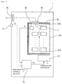
- the battery rental apparatus 1 includes a temperature preservation section 30 which surrounds a battery accommodation section 23, which accommodates accommodating a plurality of batteries 7 therein, except the front.
- the temperature preservation section 30 is formed from a heat insulating material which is superior in heat insulating property.
- a charger 18 and a power supply 19 for charging the plurality of batteries 7 are arranged at a bottom portion of the battery rental apparatus 1.
- Those heat sources can be utilized to raise the temperature of the batteries together with a heater.
- the temperature control means is composed of a temperature preservation section 30 which surrounds a battery accommodation section 23, at least one temperature sensor 32 provided in the battery accommodation section 23 or at least one external air temperature sensor 31 provided outside the apparatus, a temperature regulator 34 for varying the temperature of the temperature preservation section 30 based on a temperature signal (Ti, To) from the temperature sensor (32, 31), and a temperature control section 33 for driving the temperature regulator 34.
- the temperature preservation section 30 is formed such that it covers all faces of the battery accommodation section 23 except the front face (battery taking out section) with a heat insulating material so that the temperature variation in the battery accommodation section 23 may be suppressed small.
- a cutaway portion 30B is provided at a top face portion of the temperature preservation section 30, and an intake fan 35 is arranged there.
- Another cutaway portion 30A is provided on a bottom face portion of the temperature preservation section 30 so that warm wind or cool find may be blown into the battery accommodation section 23 from the temperature regulator 34.
- At least one temperature sensor 32 is provided in the battery accommodation section 23, and detects the temperature Ti in the battery accommodation section 23 and supplies a temperature signal Ti to the temperature control section 33.
- At least one external air temperature sensor 31 is arranged on a case of the battery rental apparatus 1, and detects an external air temperature To and supplies an external air temperature signal To to the temperature control section 33.
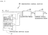
- the temperature control section 33 includes temperature setting means, comparison means, and control signal generation means, and compares the temperature signal Ti supplied thereto from the temperature sensor 32 or the external air temperature signal To supplied thereto from the external air temperature sensor 31 and supplies a control signal Vo to the temperature regulator 34 based on a result of the detection.
- the temperature control section 33 includes temperature setting means 41, comparison means 44 and control signal generation means 45.
- the temperature setting means 41 includes upper limit temperature setting means 42 and lower limit temperature setting means 43.
- the upper limit temperature setting means 42 is formed from a reloadable memory such as a RAM, and stores an upper limit value (for example, 30° C) to the preservation temperature for the batteries 7 and supplies an upper limit temperature signal Tu to the comparison means 44.
- an upper limit value for example, 30° C
- the lower limit temperature setting means 43 is formed from a reloadable memory such as a RAM, and stores a lower limit value (for example, 10° C) to the preservation temperature for the batteries 7 and supplies a lower limit temperature signal Td to the comparison means 44.
- a lower limit value for example, 10° C
- the upper limit value and the lower limit value to the preservation temperature can be externally set freely upon installation of the battery rental apparatus 1 or in response to the season.
- the comparison means 44 is formed from a comparator, an amplifier and so forth, and compares the temperature signal Ti or the external air temperature signal To with the upper limit temperature signal Tu and the lower limit temperature signal Td.
- the control signal generation means 45 is formed from a signal generator and supplies a control signal Vo corresponding to the temperature deviation signal ⁇ T to the temperature regulator 34.
- the temperature regulator 34 is formed from a cooler and a heater, and is driven based on the control signal Vo supplied thereto from the temperature control section 33 to send warm wind or cool wind (indicated by an alternate long and short dash line in FIG. 5) into the battery accommodation section 23 through the cutaway portion 30A of the temperature preservation section 30.
- a fan 36 is provided at a cutaway portion for ventilation provided at an upper portion of the apparatus case and exhausts wind sent thereto from the fan 35 to the outside of the apparatus.
- the invention provides a battery rental apparatus superior in convenience which can keep the preservation temperature of a battery within a fixed temperature range and can be installed at any place.
- a battery rental apparatus 1 which includes temperature control means which is composed of a temperature preservation section 30 which surrounds a battery accommodation section 23, a temperature sensor 32 or an external air temperature sensor 31, a temperature regulator 34 for varying the temperature of the temperature preservation section 30 based on a temperature signal Ti, To from the temperature sensor 32, 31 , and a temperature control section 33 for driving the temperature regulator 34.
Landscapes
- Engineering & Computer Science (AREA)
- Manufacturing & Machinery (AREA)
- Chemical & Material Sciences (AREA)
- Chemical Kinetics & Catalysis (AREA)
- Electrochemistry (AREA)
- General Chemical & Material Sciences (AREA)
- Transportation (AREA)
- Power Engineering (AREA)
- Mechanical Engineering (AREA)
- Automation & Control Theory (AREA)
- General Physics & Mathematics (AREA)
- Physics & Mathematics (AREA)
- Sustainable Development (AREA)
- Life Sciences & Earth Sciences (AREA)
- Sustainable Energy (AREA)
- Secondary Cells (AREA)
- Charge And Discharge Circuits For Batteries Or The Like (AREA)
- Battery Mounting, Suspending (AREA)
- Vehicle Cleaning, Maintenance, Repair, Refitting, And Outriggers (AREA)
- Electric Propulsion And Braking For Vehicles (AREA)
Abstract
Description
Claims (5)
- A battery rental apparatus which includes a battery accommodation section (23) for accommodating therein a plurality of removable batteries (7) to be carried on an electrically-operated vehicle and which recovers a battery to be returned from a user and lends a battery charged already, characterized in thatit comprises temperature control means (30-36) for keeping said battery accommodation section within a predetermined temperature range.
- A battery rental apparatus according to claim 1, characterized in that said temperature control means includes (30-36) a temperature preservation section (30) which wraps said battery accommodation section (23), at least one sensor (32) provided in said battery accommodation section (23) or at least one external air temperature sensor (31) provided outside said apparatus (1), a temperature regulator (34) for varying the temperature of said temperature preservation section (30) based on a temperature signal from said temperature sensor (32,31), and a temperature control section (33) for driving said temperature regulator (34).
- A battery rental apparatus according to claim 2, characterized in that said temperature control section (33) includes temperature setting means (41) for setting preservation temperatures of an upper limit and a lower limit for the batteries, comparison means (44) for comparing the preservation temperatures and the temperature detected by said temperature sensor (32) or said external air temperature sensor (31), and control signal generation means (45) for controlling driving of said temperature regulator (34) based on a temperature deviation detected by said comparison means (44).
- A battery rental apparatus according to claim 2, characterized in that said temperature preservation section (30) is formed from a heat insulating material and has a cutaway portion (30A,B) for ventilation and a fan (35) for ventilation provided at an upper portion and a lower portion thereof.
- A battery rental apparatus according to claim 1, characterized in that an apparatus case (30) has a cutaway portion (30A,B) for ventilation and a fan (35) for ventilation provided therein.
Applications Claiming Priority (3)
| Application Number | Priority Date | Filing Date | Title |
|---|---|---|---|
| JP26938397A JP3765913B2 (en) | 1997-09-15 | 1997-09-15 | Battery rental equipment |
| JP269383/97 | 1997-09-15 | ||
| JP26938397 | 1997-09-15 |
Publications (3)
| Publication Number | Publication Date |
|---|---|
| EP0902348A2 true EP0902348A2 (en) | 1999-03-17 |
| EP0902348A3 EP0902348A3 (en) | 2000-02-23 |
| EP0902348B1 EP0902348B1 (en) | 2003-04-02 |
Family
ID=17471650
Family Applications (1)
| Application Number | Title | Priority Date | Filing Date |
|---|---|---|---|
| EP19980116854 Expired - Lifetime EP0902348B1 (en) | 1997-09-15 | 1998-09-07 | Battery rental apparatus |
Country Status (6)
| Country | Link |
|---|---|
| EP (1) | EP0902348B1 (en) |
| JP (1) | JP3765913B2 (en) |
| CN (1) | CN1089198C (en) |
| DE (1) | DE69812812T2 (en) |
| ES (1) | ES2196445T3 (en) |
| TW (1) | TW392382B (en) |
Cited By (10)
| Publication number | Priority date | Publication date | Assignee | Title |
|---|---|---|---|---|
| FR2794289A1 (en) * | 1999-05-25 | 2000-12-01 | Honda Motor Co Ltd | Battery exchange installation for electrically powered vehicles, particularly bicycles |
| GB2416632A (en) * | 2004-07-23 | 2006-02-01 | Ford Global Tech Llc | An electrical storage device heater for a vehicle |
| FR2876504A1 (en) * | 2004-10-07 | 2006-04-14 | Yi Chieh Wu | INTERNAL VENTILATION STRUCTURE OF BATTERY HOUSING FOR CONTROLLING THE TEMPERATURE REGENERATING THROUGH THE SAME |
| WO2011009609A2 (en) | 2009-07-23 | 2011-01-27 | Li-Tec Battery Gmbh | Charging apparatus for electric energy stores, supply station, and method for charging electric energy stores |
| US20130113424A1 (en) * | 2011-09-29 | 2013-05-09 | Michael Lynn Froelich | Temperature-controlled external battery charger and standardized, manually-changable modular battery system for electric-powered vehicles and craft |
| WO2016036742A1 (en) | 2014-09-04 | 2016-03-10 | Gogoro Inc. | Apparatus, system, and method for vending, charging, and two-way distribution of electrical energy storage devices |
| US9469202B2 (en) | 2006-07-04 | 2016-10-18 | Campagnolo S.R.L. | Method for controlling and system for charging a battery power supply unit |
| US9634518B2 (en) | 2006-07-04 | 2017-04-25 | Campagnolo S.R.L. | Method and system for supplying electrical energy from a battery power supply unit to a heating element |
| CN109490787A (en) * | 2017-12-15 | 2019-03-19 | 蔚来汽车有限公司 | Battery replacement fault diagnosis method and system |
| US12495528B2 (en) | 2020-10-07 | 2025-12-09 | Honda Motor Co., Ltd. | Accommodating device and electric power system |
Families Citing this family (5)
| Publication number | Priority date | Publication date | Assignee | Title |
|---|---|---|---|---|
| JP6096447B2 (en) * | 2012-09-13 | 2017-03-15 | 株式会社東芝 | Storage battery management device and storage battery management system |
| CN104620289A (en) * | 2015-02-14 | 2015-05-13 | 深圳来电科技有限公司 | Mobile power return method, system and lease terminal |
| CN104966321A (en) * | 2015-06-26 | 2015-10-07 | 蒋金森 | Urban electric car renting automatic control system |
| WO2021005703A1 (en) * | 2019-07-09 | 2021-01-14 | 本田技研工業株式会社 | Information providing device, information providing method, and program |
| JPWO2022131292A1 (en) * | 2020-12-16 | 2022-06-23 |
Family Cites Families (2)
| Publication number | Priority date | Publication date | Assignee | Title |
|---|---|---|---|---|
| JP2691117B2 (en) * | 1993-04-06 | 1997-12-17 | 有限会社日本ホーム経済研究所 | Rechargeable battery charger for electric vehicles |
| JP3515859B2 (en) * | 1995-09-29 | 2004-04-05 | 株式会社リコー | Battery charge processing device and battery charge processing system |
-
1997
- 1997-09-15 JP JP26938397A patent/JP3765913B2/en not_active Expired - Fee Related
-
1998
- 1998-08-28 TW TW087114262A patent/TW392382B/en not_active IP Right Cessation
- 1998-09-07 DE DE69812812T patent/DE69812812T2/en not_active Expired - Fee Related
- 1998-09-07 EP EP19980116854 patent/EP0902348B1/en not_active Expired - Lifetime
- 1998-09-07 ES ES98116854T patent/ES2196445T3/en not_active Expired - Lifetime
- 1998-09-14 CN CN98119247A patent/CN1089198C/en not_active Expired - Fee Related
Cited By (19)
| Publication number | Priority date | Publication date | Assignee | Title |
|---|---|---|---|---|
| FR2808123A1 (en) * | 1999-05-25 | 2001-10-26 | Honda Motor Co Ltd | BATTERY EXCHANGE DEVICE |
| FR2794289A1 (en) * | 1999-05-25 | 2000-12-01 | Honda Motor Co Ltd | Battery exchange installation for electrically powered vehicles, particularly bicycles |
| US8569656B2 (en) | 2004-07-23 | 2013-10-29 | Ford Global Technologies, Llc | Electrical storage device heater for vehicle |
| GB2416632A (en) * | 2004-07-23 | 2006-02-01 | Ford Global Tech Llc | An electrical storage device heater for a vehicle |
| GB2416632B (en) * | 2004-07-23 | 2008-02-20 | Ford Global Tech Llc | An electrical storage device heater for a vehicle |
| US10594005B2 (en) | 2004-07-23 | 2020-03-17 | Ford Global Technologies, Llc | Electrical storage device heater for vehicle |
| FR2876504A1 (en) * | 2004-10-07 | 2006-04-14 | Yi Chieh Wu | INTERNAL VENTILATION STRUCTURE OF BATTERY HOUSING FOR CONTROLLING THE TEMPERATURE REGENERATING THROUGH THE SAME |
| LU91164B1 (en) * | 2004-10-07 | 2006-11-16 | Yi-Chieh Wu | Battery box with a cooler |
| NL1029593C2 (en) * | 2004-10-07 | 2007-06-05 | Yi-Chieh Wu | Ventilation structure incorporated in a battery housing for controlling the temperature therein. |
| US9634518B2 (en) | 2006-07-04 | 2017-04-25 | Campagnolo S.R.L. | Method and system for supplying electrical energy from a battery power supply unit to a heating element |
| US9469202B2 (en) | 2006-07-04 | 2016-10-18 | Campagnolo S.R.L. | Method for controlling and system for charging a battery power supply unit |
| DE102009034371A1 (en) | 2009-07-23 | 2011-01-27 | Li-Tec Battery Gmbh | Charger for electric energy storage, supply station and method for charging electric energy storage |
| WO2011009609A3 (en) * | 2009-07-23 | 2011-04-21 | Li-Tec Battery Gmbh | Charging apparatus for electric energy stores, supply station, and method for charging electric energy stores |
| WO2011009609A2 (en) | 2009-07-23 | 2011-01-27 | Li-Tec Battery Gmbh | Charging apparatus for electric energy stores, supply station, and method for charging electric energy stores |
| US20130113424A1 (en) * | 2011-09-29 | 2013-05-09 | Michael Lynn Froelich | Temperature-controlled external battery charger and standardized, manually-changable modular battery system for electric-powered vehicles and craft |
| WO2016036742A1 (en) | 2014-09-04 | 2016-03-10 | Gogoro Inc. | Apparatus, system, and method for vending, charging, and two-way distribution of electrical energy storage devices |
| EP3188926A4 (en) * | 2014-09-04 | 2019-06-19 | Gogoro Inc. | APPARATUS, SYSTEM AND METHOD FOR SELLING, CHARGING AND BILATERAL DISTRIBUTION OF ELECTRIC POWER STORAGE DEVICES |
| CN109490787A (en) * | 2017-12-15 | 2019-03-19 | 蔚来汽车有限公司 | Battery replacement fault diagnosis method and system |
| US12495528B2 (en) | 2020-10-07 | 2025-12-09 | Honda Motor Co., Ltd. | Accommodating device and electric power system |
Also Published As
| Publication number | Publication date |
|---|---|
| CN1089198C (en) | 2002-08-14 |
| EP0902348A3 (en) | 2000-02-23 |
| EP0902348B1 (en) | 2003-04-02 |
| ES2196445T3 (en) | 2003-12-16 |
| JPH1198613A (en) | 1999-04-09 |
| DE69812812T2 (en) | 2003-11-13 |
| CN1211843A (en) | 1999-03-24 |
| JP3765913B2 (en) | 2006-04-12 |
| DE69812812D1 (en) | 2003-05-08 |
| TW392382B (en) | 2000-06-01 |
Similar Documents
| Publication | Publication Date | Title |
|---|---|---|
| EP0902348B1 (en) | Battery rental apparatus | |
| JP7040601B2 (en) | Battery control device, battery control method, uninterruptible power supply, power system and electric vehicle | |
| USRE37678E1 (en) | Secondary battery power storage system | |
| US9000728B2 (en) | Vehicular electric charge control apparatus and emergency notification system | |
| EP0539640A1 (en) | Improvements in or relating to batteries | |
| JP3136926B2 (en) | Storage battery status management system | |
| US11325475B2 (en) | Battery pack and transportation apparatus including the battery pack | |
| US6928372B2 (en) | Method for estimating time to full-charge in a rechargeable battery | |
| US6262559B1 (en) | Portable auxiliary charging battery pack for thin metal film battery power pack | |
| JPH0773906A (en) | Charger for electric vehicle | |
| US20220045546A1 (en) | Battery charging system, charging device, information processing device, battery charging method, program, and storage medium | |
| FR2965986A1 (en) | ENERGY EXCHANGE SYSTEM | |
| JP2015204149A (en) | Power storage device, control method, control device, power storage system, maintenance system, electric vehicle and electronic apparatus | |
| WO1999065131A1 (en) | Energy storage system | |
| EP0964470A4 (en) | BATTERY SUPPLY SOURCE | |
| JP2010200574A (en) | Self-diagnosis circuit and power supply | |
| CA2487546C (en) | Method for supplementing and calculating energy consumed by a vehicle | |
| US20100013647A1 (en) | Hybrid power system | |
| US20250038545A1 (en) | Battery pack, and apparatus and method for managing same | |
| US20100060241A1 (en) | Method and device for determining an equalizing charge of an accumulator | |
| USRE39908E1 (en) | Secondary battery power storage system | |
| US20190172127A1 (en) | Information processing device, information processing method, and information processing system | |
| CN222272398U (en) | Unmanned aerial vehicle battery management equipment | |
| CN216774340U (en) | Shared battery management device | |
| EP0495881A1 (en) | Portable power supplies |
Legal Events
| Date | Code | Title | Description |
|---|---|---|---|
| PUAI | Public reference made under article 153(3) epc to a published international application that has entered the european phase |
Free format text: ORIGINAL CODE: 0009012 |
|
| AK | Designated contracting states |
Kind code of ref document: A2 Designated state(s): DE ES FR IT NL |
|
| AX | Request for extension of the european patent |
Free format text: AL;LT;LV;MK;RO;SI |
|
| PUAL | Search report despatched |
Free format text: ORIGINAL CODE: 0009013 |
|
| AK | Designated contracting states |
Kind code of ref document: A3 Designated state(s): AT BE CH CY DE DK ES FI FR GB GR IE IT LI LU MC NL PT SE |
|
| AX | Request for extension of the european patent |
Free format text: AL;LT;LV;MK;RO;SI |
|
| 17P | Request for examination filed |
Effective date: 20000515 |
|
| AKX | Designation fees paid |
Free format text: DE ES FR IT NL |
|
| GRAH | Despatch of communication of intention to grant a patent |
Free format text: ORIGINAL CODE: EPIDOS IGRA |
|
| GRAH | Despatch of communication of intention to grant a patent |
Free format text: ORIGINAL CODE: EPIDOS IGRA |
|
| GRAA | (expected) grant |
Free format text: ORIGINAL CODE: 0009210 |
|
| AK | Designated contracting states |
Designated state(s): DE ES FR IT NL |
|
| REF | Corresponds to: |
Ref document number: 69812812 Country of ref document: DE Date of ref document: 20030508 Kind code of ref document: P |
|
| PGFP | Annual fee paid to national office [announced via postgrant information from national office to epo] |
Ref country code: ES Payment date: 20030916 Year of fee payment: 6 |
|
| ET | Fr: translation filed | ||
| REG | Reference to a national code |
Ref country code: ES Ref legal event code: FG2A Ref document number: 2196445 Country of ref document: ES Kind code of ref document: T3 |
|
| PLBE | No opposition filed within time limit |
Free format text: ORIGINAL CODE: 0009261 |
|
| STAA | Information on the status of an ep patent application or granted ep patent |
Free format text: STATUS: NO OPPOSITION FILED WITHIN TIME LIMIT |
|
| 26N | No opposition filed |
Effective date: 20040105 |
|
| PG25 | Lapsed in a contracting state [announced via postgrant information from national office to epo] |
Ref country code: ES Free format text: LAPSE BECAUSE OF NON-PAYMENT OF DUE FEES Effective date: 20040908 |
|
| PGFP | Annual fee paid to national office [announced via postgrant information from national office to epo] |
Ref country code: FR Payment date: 20050823 Year of fee payment: 8 |
|
| PGFP | Annual fee paid to national office [announced via postgrant information from national office to epo] |
Ref country code: DE Payment date: 20050902 Year of fee payment: 8 |
|
| PGFP | Annual fee paid to national office [announced via postgrant information from national office to epo] |
Ref country code: NL Payment date: 20050904 Year of fee payment: 8 |
|
| PG25 | Lapsed in a contracting state [announced via postgrant information from national office to epo] |
Ref country code: IT Free format text: LAPSE BECAUSE OF NON-PAYMENT OF DUE FEES Effective date: 20050907 |
|
| REG | Reference to a national code |
Ref country code: ES Ref legal event code: FD2A Effective date: 20040908 |
|
| PG25 | Lapsed in a contracting state [announced via postgrant information from national office to epo] |
Ref country code: NL Free format text: LAPSE BECAUSE OF NON-PAYMENT OF DUE FEES Effective date: 20070401 |
|
| PG25 | Lapsed in a contracting state [announced via postgrant information from national office to epo] |
Ref country code: DE Free format text: LAPSE BECAUSE OF NON-PAYMENT OF DUE FEES Effective date: 20070403 |
|
| NLV4 | Nl: lapsed or anulled due to non-payment of the annual fee |
Effective date: 20070401 |
|
| REG | Reference to a national code |
Ref country code: FR Ref legal event code: ST Effective date: 20070531 |
|
| PG25 | Lapsed in a contracting state [announced via postgrant information from national office to epo] |
Ref country code: FR Free format text: LAPSE BECAUSE OF NON-PAYMENT OF DUE FEES Effective date: 20061002 |