EP0902301A1 - Optoelectronic observation apparatus improved to detect laser shots - Google Patents
Optoelectronic observation apparatus improved to detect laser shots Download PDFInfo
- Publication number
- EP0902301A1 EP0902301A1 EP98402183A EP98402183A EP0902301A1 EP 0902301 A1 EP0902301 A1 EP 0902301A1 EP 98402183 A EP98402183 A EP 98402183A EP 98402183 A EP98402183 A EP 98402183A EP 0902301 A1 EP0902301 A1 EP 0902301A1
- Authority
- EP
- European Patent Office
- Prior art keywords
- video
- observation device
- images
- laser
- difference
- Prior art date
- Legal status (The legal status is an assumption and is not a legal conclusion. Google has not performed a legal analysis and makes no representation as to the accuracy of the status listed.)
- Granted
Links
Images

Classifications
-
- G—PHYSICS
- G02—OPTICS
- G02B—OPTICAL ELEMENTS, SYSTEMS OR APPARATUS
- G02B23/00—Telescopes, e.g. binoculars; Periscopes; Instruments for viewing the inside of hollow bodies; Viewfinders; Optical aiming or sighting devices
- G02B23/12—Telescopes, e.g. binoculars; Periscopes; Instruments for viewing the inside of hollow bodies; Viewfinders; Optical aiming or sighting devices with means for image conversion or intensification
-
- G—PHYSICS
- G01—MEASURING; TESTING
- G01S—RADIO DIRECTION-FINDING; RADIO NAVIGATION; DETERMINING DISTANCE OR VELOCITY BY USE OF RADIO WAVES; LOCATING OR PRESENCE-DETECTING BY USE OF THE REFLECTION OR RERADIATION OF RADIO WAVES; ANALOGOUS ARRANGEMENTS USING OTHER WAVES
- G01S7/00—Details of systems according to groups G01S13/00, G01S15/00, G01S17/00
- G01S7/48—Details of systems according to groups G01S13/00, G01S15/00, G01S17/00 of systems according to group G01S17/00
- G01S7/483—Details of pulse systems
Definitions
- the present invention relates to devices observation systems with optical system for observation a field, an associated optoelectronic detector audit optical system to form the electronic image of said field and of video means receiving said image electronic and displaying the corresponding video image of said field.
- the object of the present invention is to improve an observation device of the type mentioned above and protected by the aforementioned protection device, so to alert said observer to the fact that a beam laser has reached said observation device.
- the two successive electronic images are identical, of so their difference is zero and nothing is superimposed video images appearing on said video means.
- the protective device reflects and absorbs the corresponding laser beam, so that, on the sensitive optoelectronic element of said detector, the pixel or pixels corresponding to the location where said laser beam hit are obscured.
- the difference between said successive images is no longer null, but on the contrary formed by said one or more darkened pixels.
- said video control means accentuate the obscured pixel (s) to make them appear unambiguously on said display means video.
- said pixels video control means can, on said means display, magnify those obscured pixels, or display a particular mark centered on said pixels, such as a circle, a crosshair, etc.
- said video control means can make fixes the image displayed on said display means video, when said difference is representative of a laser shot.
- Said video control means can also order additional memory means for store, in the event that a laser shot reaches said device of observation, the image resulting from the overlay of said difference and one of said video images displayed corresponding.
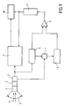
- Figure 1 shows the block diagram of a device advanced optoelectronic observation to the present invention.
- Figures 2A, 2B and 2C illustrate the operation of the optoelectronic observation device of the Figure 1, when no laser shot reaches said device.
- Figures 3A, 3B, 3C and 3D illustrate the operation of the optoelectronic observation device of Figure 1, when a laser shot reaches said device.
- the observation device illustrated schematically in Figure 1, includes an optical system 1 observing an optical field C from which it receives beams luminous F.
- the optical system 1 is associated with a detector optoelectronics 2, which forms an electronic image of said field, and is protected against laser fire by a protection device 3 of the type described in the application French patent n ° 96 12295 dated October 9, 1996.
- This device protection 3 lets all the light rays through, except for the laser beams it reflects and absorbs.
- the electronic image generated by the detector optoelectronics 2 is transmitted to video means 4 which display the corresponding video image of field C observed by the optical system 1.
- the observation device of FIG. 1 comprises in addition two electronic memories 5 and 6 and a device 7 image transfer, synchronized with sequencing said images in the optoelectronic detector 2.
- the input of the electronic memory 5 is connected at the output of the optoelectronic detector 2, in parallel with video resources 4.
- the electronic image It appearing at the output of the optoelectronic detector 2 is simultaneously displayed on the video means 4 and stored in memory 5.
- the previous electronic image It is transferred into memory 6 by the transfer 7, while the current electronic image It + dt is simultaneously displayed on video means 4 and stored in memory 5.
- the electronic image previous It + dt is transferred to memory 6 by the transfer device 7, while the electronic image It + 2dt is simultaneously displayed on the video means and stored in memory 5, etc ...
- memory 5 contains the current image of field C
- the memory 6 contains the previous image of said field.
- the outputs of memories 5 and 6 are respectively connected to two inputs of a subtractor 8, the output of which is connected to the video means 4 by superposition means 9.
- the observer looking at said display means video 4 is therefore alerted to the laser shot aimed at the observation device and it can determine the origin of this laser shot.
- the device according to the present invention can have an additional memory 10 in which is stored, under the control of said video control means 9, the image of field C with the superimposed r reticle, as shown in Figure 3D.
Abstract
Description
La présente invention concerne les dispositifs d'observation pourvus d'un système optique pour l'observation d'un champ, d'un détecteur optoélectronique associé audit système optique pour former l'image électronique dudit champ et de moyens vidéo recevant ladite image électronique et affichant l'image vidéo correspondante dudit champ.The present invention relates to devices observation systems with optical system for observation a field, an associated optoelectronic detector audit optical system to form the electronic image of said field and of video means receiving said image electronic and displaying the corresponding video image of said field.
On sait que de tels dispositifs d'observation peuvent être endommagés ou même détruits par des faisceaux laser dirigés contre eux.We know that such observation devices can be damaged or even destroyed by beams laser directed against them.
Aussi, dans la demande de brevet français n° 96 12295 déposée le 9 octobre 1996 au nom de la demanderesse, on a décrit et revendiqué un dispositif de protection contre de telles agressions laser, grâce auquel les faisceaux laser atteignant un tel dispositif d'observation sont automatiquement réfléchis et absorbés sans pouvoir endommager ou détruire ce dernier, sans même que l'observateur regardant l'image vidéo du champ en ait connaissance.Also, in French patent application n ° 96 12295 filed October 9, 1996 in the name of the plaintiff, a protection device has been described and claimed against such laser attacks, thanks to which the laser beams reaching such an observation device are automatically reflected and absorbed without power damage or destroy it, without even the observer watching the video image of the field knowledge.
La présente invention a pour objet de perfectionner un dispositif d'observation du type rappelé ci-dessus et protégé par le dispositif de protection précité, afin d'alerter ledit observateur sur le fait qu'un faisceau laser a atteint ledit dispositif d'observation.The object of the present invention is to improve an observation device of the type mentioned above and protected by the aforementioned protection device, so to alert said observer to the fact that a beam laser has reached said observation device.
A cette fin, selon l'invention, le dispositif d'observation comprenant :
- un système optique pour l'observation d'un champ dans lequel sont susceptibles de se produire des tirs laser ;
- un détecteur optoélectronique associé audit système optique pour former une suite d'images électroniques dudit champ ;
- des moyens d'affichage vidéo recevant lesdites images électroniques et affichant les images vidéo dudit champ correspondantes ; et
- un dispositif de protection réfléchissant et absorbant les faisceaux laser atteignant ledit dispositif d'observation,
- des moyens de mémoire susceptibles de stocker au moins deux images électroniques successives dudit champ ;
- des moyens de soustraction permettant de soustraire l'une desdites images électroniques de l'autre pour en obtenir la différence ; et
- des moyens de commande vidéo permettant de superposer ladite différence auxdites images vidéo affichées par lesdits moyens d'affichage vidéo, au moins dans le cas où un tir laser a atteint ledit dispositif d'observation.
- an optical system for the observation of a field in which laser shots are likely to occur;
- an optoelectronic detector associated with said optical system to form a series of electronic images of said field;
- video display means receiving said electronic images and displaying video images of said corresponding field; and
- a protective device reflecting and absorbing the laser beams reaching said observation device,
- memory means capable of storing at least two successive electronic images of said field;
- subtraction means making it possible to subtract one of said electronic images from the other to obtain the difference therefrom; and
- video control means making it possible to superimpose said difference on said video images displayed by said video display means, at least in the case where a laser shot has reached said observation device.
Ainsi, lorsqu'aucun tir laser ne se produit, les deux images électroniques successives sont identiques, de sorte que leur différence est nulle et rien n'est superposé aux images vidéo apparaissant sur lesdits moyens vidéo. En revanche, lorsqu'un tir laser atteint le dispositif d'observation, le dispositif de protection réfléchit et absorbe le faisceau laser correspondant, de sorte que, sur l'élément optoélectronique sensible dudit détecteur, le ou les pixels correspondant à l'emplacement où ledit faisceau laser a frappé sont obscurcis. Par suite, la différence entre lesdites images successives n'est plus nulle, mais au contraire formée par ledit ou lesdits pixels obscurcis. Ceux-ci étant superposés aux images vidéo affichées, ils indiquent sur celles-ci l'endroit d'où est parti ledit tir laser, puisque, à travers ledit système optique, l'origine du tir laser, le centre du système optique et lesdits pixels obscurcis sont alignés. Thus, when no laser fire occurs, the two successive electronic images are identical, of so their difference is zero and nothing is superimposed video images appearing on said video means. On the other hand, when a laser shot reaches the device the protective device reflects and absorbs the corresponding laser beam, so that, on the sensitive optoelectronic element of said detector, the pixel or pixels corresponding to the location where said laser beam hit are obscured. As a result, the difference between said successive images is no longer null, but on the contrary formed by said one or more darkened pixels. These being superimposed on the video images displayed, they indicate on them where is gone said laser shot, since, through said system optics, the origin of the laser shot, the center of the system optical and said obscured pixels are aligned.
Ainsi, en observant lesdits moyens d'affichage vidéo, l'observateur est alerté (par l'apparition du ou des pixels obscurcis) qu'un tir laser est dirigé contre lui et il connaít l'origine de ce tir laser.Thus, by observing said video display means, the observer is alerted (by the appearance of the darkened pixels) a laser shot is aimed at it and he knows the origin of this laser shot.
Avantageusement, afin d'attirer clairement l'attention dudit observateur, lesdits moyens de commande vidéo accentuent le ou les pixels obscurcis pour les faire apparaítre sans ambiguïté sur lesdits moyens d'affichage vidéo.Advantageously, in order to clearly attract attention said observer, said video control means accentuate the obscured pixel (s) to make them appear unambiguously on said display means video.
Pour accentuer le ou les pixels obscurcis, lesdits moyens de commande vidéo peuvent, sur lesdits moyens d'affichage vidéo, grossir ces pixels obscurcis ou afficher une marque particulière centrée sur lesdits pixels, telle qu'un cercle, un réticule, etc ...To accentuate the obscured pixel (s), said pixels video control means can, on said means display, magnify those obscured pixels, or display a particular mark centered on said pixels, such as a circle, a crosshair, etc.
De plus, pour attirer encore plus l'attention de l'observateur et lui permettre d'analyser rapidement la situation, lesdits moyens de commande vidéo peuvent rendre fixe l'image affichée sur lesdits moyens d'affichage vidéo, lorsque ladite différence est représentative d'un tir laser.In addition, to draw even more attention to the observer and allow him to quickly analyze the situation, said video control means can make fixes the image displayed on said display means video, when said difference is representative of a laser shot.
Lesdits moyens de commande vidéo peuvent également commander des moyens de mémoire supplémentaires pour stocker, dans le cas où un tir laser atteint ledit dispositif d'observation, l'image résultant de la superposition de ladite différence et d'une desdites images vidéo affichée correspondantes.Said video control means can also order additional memory means for store, in the event that a laser shot reaches said device of observation, the image resulting from the overlay of said difference and one of said video images displayed corresponding.
Ainsi, le stockage de cette image permet l'analyse ultérieure du champ observé et/ou la commande d'une riposte immédiate au tir laser ayant atteint ledit dispositif d'observation.So storing this image allows analysis the observed field and / or the command of a response immediate to laser shooting having reached said device of observation.
Les figures du dessin annexé feront bien comprendre comment l'invention peut être réalisée. Sur ces figures, des références identiques désignent des éléments semblables. The figures in the accompanying drawing will make it clear how the invention can be realized. In these figures, identical references denote similar elements.
La figure 1 montre le schéma synoptique d'un dispositif d'observation optoélectronique perfectionné conformément à la présente invention.Figure 1 shows the block diagram of a device advanced optoelectronic observation to the present invention.
Les figures 2A, 2B et 2C illustrent le fonctionnement du dispositif d'observation optoélectronique de la figure 1, lorsqu'aucun tir laser n'atteint ledit dispositif.Figures 2A, 2B and 2C illustrate the operation of the optoelectronic observation device of the Figure 1, when no laser shot reaches said device.
Les figures 3A, 3B, 3C et 3D illustrent le fonctionnement du dispositif d'observation optoélectronique de la figure 1, lorsqu'un tir laser atteint ledit dispositif.Figures 3A, 3B, 3C and 3D illustrate the operation of the optoelectronic observation device of Figure 1, when a laser shot reaches said device.
Le dispositif d'observation, illustré schématiquement
sur la figure 1, comporte un système optique 1 observant
un champ optique C duquel il reçoit des faisceaux
lumineux F. Le système optique 1 est associé à un détecteur
optoélectronique 2, qui forme une image électronique
dudit champ, et est protégé contre les tirs lasers par un
dispositif de protection 3 du type décrit dans la demande
de brevet français n° 96 12295 du 9 octobre 1996. Ce dispositif
de protection 3 laisse passer tous les rayons lumineux,
à l'exception des faisceaux laser qu'il réfléchit
et absorbe. L'image électronique engendrée par le détecteur
optoélectronique 2 est transmise à des moyens vidéo
4 qui affichent l'image vidéo correspondante du champ C
observé par le système optique 1.The observation device, illustrated schematically
in Figure 1, includes an
Le dispositif d'observation de la figure 1 comporte
de plus deux mémoires électroniques 5 et 6 et un dispositif
de transfert d'images 7, synchronisé avec le séquencement
desdites images dans le détecteur optoélectronique
2. De plus, l'entrée de la mémoire électronique 5 est reliée
à la sortie du détecteur optoélectronique 2, en parallèle
avec les moyens vidéo 4.The observation device of FIG. 1 comprises
in addition two
Ainsi, à un instant t, l'image électronique It apparaissant
à la sortie du détecteur optoélectronique 2
est, simultanément, affichée sur les moyens vidéo 4 et
enregistrée dans la mémoire 5. A l'instant suivant t+dt
du séquencement d'images, l'image électronique précédente
It est transférée dans la mémoire 6 par le dispositif de
transfert 7, tandis que l'image électronique actuelle
It+dt est, simultanément, affichée sur les moyens vidéo 4
et stockée dans la mémoire 5. De même, à l'instant suivant
t+2dt du séquencement d'images, l'image électronique
précédente It+dt est transférée dans la mémoire 6 par le
dispositif de transfert 7, tandis que l'image électronique
actuelle It+2dt est, simultanément, affichée sur les
moyens vidéo et stockée dans la mémoire 5, etc ... Ainsi,
à chaque instant du séquencement d'images, la mémoire 5
contient l'image actuelle du champ C, tandis que la mémoire
6 contient l'image précédente dudit champ.Thus, at an instant t, the electronic image It appearing
at the output of the
Les sorties des mémoires 5 et 6 sont respectivement
reliées à deux entrées d'un soustracteur 8, dont la sortie
est reliée aux moyens vidéo 4 par des moyens de superposition
9.The outputs of
Ainsi, comme l'illustrent les figures 2A et 2B, si
les deux images électroniques It et It+dt sont identiques,
leur différence It+dt - It (figure 2C) apparaissant
à la sortie du soustracteur 8 est nulle et les moyens de
superposition 9 n'ont rien à superposer à l'image vidéo
affichée par les moyens vidéo 4.Thus, as illustrated in FIGS. 2A and 2B, if
the two electronic images It and It + dt are identical,
their difference It + dt - It (figure 2C) appearing
at the output of
En revanche, si à l'instant t+dt un tir laser 1,
correspondant à la bande de fonctionnement du détecteur 2
et dont l'énergie est telle qu'il peut être réfléchi
et/ou absorbé par le dispositif de protection 3, atteint
ledit dispositif d'observation, l'image électronique correspondante
It+dt comporte au moins un pixel obscurci n
(voir la figure 3A). Par suite, si à l'instant précédent
(voir la figure 3B), il n'y a eu aucun tir laser, la différence
entre les images It+dt - It (voir la figure 3C)
est constituée desdits pixels obscurcis, qui sont superposés,
sur les moyens d'affichage vidéo 4, à l'image vidéo
en cours d'affichage par les moyens de commande vidéo
9. De plus, ces derniers peuvent rendre fixe ladite image
vidéo et/ou lui superposer un réticule r centré sur ledit
pixel obscurci (voir la figure 3D).On the other hand, if at time t + dt a
L'observateur regardant lesdits moyens d'affichage
vidéo 4 est donc alerté du tir laser dirigé contre le
dispositif d'observation et il peut déterminer l'origine
de ce tir laser.The observer looking at said display means
Le dispositif conforme à la présente invention peut
comporter une mémoire supplémentaire 10 dans laquelle est
stockée, sous la commande desdits moyens de commande vidéo
9, l'image du champ C avec le réticule r superposé,
comme montré sur la figure 3D.The device according to the present invention can
have an
Claims (6)
caractérisé en ce que, dans le cas où un tir laser a atteint ledit dispositif d'observation, ladite différence est formée d'au moins un pixel d'image obscurci (n) et en ce que lesdits moyens de commande vidéo (9) accentuent ledit pixel obscurci pour qu'il apparaisse clairement sur lesdits moyens d'affichage vidéo (4). Observation device according to claim 1,
characterized in that, in the event that a laser shot has reached said observation device, said difference is formed by at least one obscured image pixel (n) and in that said video control means (9) accentuate said pixel obscured so that it appears clearly on said video display means (4).
caractérisé en ce que, pour accentuer ledit pixel obscurci (n), lesdits moyens de commande vidéo (9) affichent, sur lesdits moyens d'affichage vidéo (4), une marque (r) centrée sur ledit pixel obscurci.Observation device according to claim 2,
characterized in that, to emphasize said obscured pixel (n), said video control means (9) display, on said video display means (4), a mark (r) centered on said obscured pixel.
caractérisé en ce que ladite marque est un réticule (r).Observation device according to claim 3,
characterized in that said mark is a reticle (r).
caractérisé en ce que lesdits moyens de commande vidéo (9) rendent fixe l'image affichée sur lesdits moyens d'affichage vidéo, lorsque ladite différence est représentative d'un tir laser.Observation device according to one of claims 1 to 4,
characterized in that said video control means (9) fixes the image displayed on said video display means, when said difference is representative of a laser shot.
caractérisé en ce qu'il comporte des moyens de mémoire supplémentaires (10) pour stocker, dans le cas où un tir laser a atteint le dispositif d'observation, l'image résultant de la superposition de ladite différence et d'une desdites images vidéo affichée correspondantes.Observation device according to one of claims 1 to 5,
characterized in that it comprises additional memory means (10) for storing, in the case where a laser shot has reached the observation device, the image resulting from the superimposition of said difference and one of said video images displayed corresponding.
Applications Claiming Priority (2)
| Application Number | Priority Date | Filing Date | Title |
|---|---|---|---|
| FR9711157A FR2768235B1 (en) | 1997-09-09 | 1997-09-09 | IMPROVED OPTOELECTRONIC OBSERVATION DEVICE FOR DETECTING LASER SHOTS |
| FR9711157 | 1997-09-09 |
Publications (2)
| Publication Number | Publication Date |
|---|---|
| EP0902301A1 true EP0902301A1 (en) | 1999-03-17 |
| EP0902301B1 EP0902301B1 (en) | 2003-07-09 |
Family
ID=9510870
Family Applications (1)
| Application Number | Title | Priority Date | Filing Date |
|---|---|---|---|
| EP19980402183 Expired - Lifetime EP0902301B1 (en) | 1997-09-09 | 1998-09-03 | Optoelectronic observation apparatus improved to detect laser shots |
Country Status (4)
| Country | Link |
|---|---|
| EP (1) | EP0902301B1 (en) |
| DE (1) | DE69816206T2 (en) |
| ES (1) | ES2197435T3 (en) |
| FR (1) | FR2768235B1 (en) |
Families Citing this family (1)
| Publication number | Priority date | Publication date | Assignee | Title |
|---|---|---|---|---|
| DE102010010030B4 (en) * | 2010-03-03 | 2013-02-21 | Diehl Bgt Defence Gmbh & Co. Kg | Device for presenting an environment |
Citations (4)
| Publication number | Priority date | Publication date | Assignee | Title |
|---|---|---|---|---|
| US4575752A (en) * | 1982-06-17 | 1986-03-11 | Michitaka Honda | Diagnostic X-ray apparatus having a master timing control unit |
| US4894721A (en) * | 1987-03-19 | 1990-01-16 | Mitsubishi Denki Kabushiki Kaisha | Method and apparatus for solid state image processing |
| US5153425A (en) * | 1990-12-24 | 1992-10-06 | United Technologies Corporation | Broadband optical limiter with sacrificial mirror to prevent irradiation of a sensor system by high intensity laser radiation |
| EP0654941A2 (en) * | 1993-11-24 | 1995-05-24 | Samsung Electronics Co., Ltd. | Motion detection circuit and method using spatial information |
-
1997
- 1997-09-09 FR FR9711157A patent/FR2768235B1/en not_active Expired - Lifetime
-
1998
- 1998-09-03 ES ES98402183T patent/ES2197435T3/en not_active Expired - Lifetime
- 1998-09-03 EP EP19980402183 patent/EP0902301B1/en not_active Expired - Lifetime
- 1998-09-03 DE DE69816206T patent/DE69816206T2/en not_active Expired - Lifetime
Patent Citations (4)
| Publication number | Priority date | Publication date | Assignee | Title |
|---|---|---|---|---|
| US4575752A (en) * | 1982-06-17 | 1986-03-11 | Michitaka Honda | Diagnostic X-ray apparatus having a master timing control unit |
| US4894721A (en) * | 1987-03-19 | 1990-01-16 | Mitsubishi Denki Kabushiki Kaisha | Method and apparatus for solid state image processing |
| US5153425A (en) * | 1990-12-24 | 1992-10-06 | United Technologies Corporation | Broadband optical limiter with sacrificial mirror to prevent irradiation of a sensor system by high intensity laser radiation |
| EP0654941A2 (en) * | 1993-11-24 | 1995-05-24 | Samsung Electronics Co., Ltd. | Motion detection circuit and method using spatial information |
Also Published As
| Publication number | Publication date |
|---|---|
| DE69816206D1 (en) | 2003-08-14 |
| FR2768235A1 (en) | 1999-03-12 |
| FR2768235B1 (en) | 2000-02-04 |
| DE69816206T2 (en) | 2004-07-29 |
| EP0902301B1 (en) | 2003-07-09 |
| ES2197435T3 (en) | 2004-01-01 |
Similar Documents
| Publication | Publication Date | Title |
|---|---|---|
| CA2027286C (en) | Device for the real time localisation of radiation sources | |
| US6803577B2 (en) | Quantitative imaging of gas emissions utilizing optical techniques | |
| US11927529B2 (en) | Gas detection system and method | |
| Rankin et al. | Passive sensor evaluation for unmanned ground vehicle mud detection | |
| FR2973344A1 (en) | AIRCRAFT WITH A MONITORING SYSTEM | |
| EP2593904A1 (en) | Multifunctional bispectral imaging method and device | |
| CA2611015A1 (en) | Protective glasses | |
| EP0902301B1 (en) | Optoelectronic observation apparatus improved to detect laser shots | |
| WO2012127312A1 (en) | Monitoring system | |
| EP1045588B1 (en) | Transmission device for digital video images | |
| FR2888333A1 (en) | Laser radiation source detection and localization device for e.g. military field , has cross network disposed between laser radiation source and imaging optical apparatus, such that diffraction orders of network are reproduced on detector | |
| US20050253927A1 (en) | Near infrared illuminated tripwire detector | |
| FR2797042A1 (en) | LASER SCANNING GUIDING METHOD AND DEVICE FROM A MISSILE TO A TARGET | |
| Storm et al. | Trip wire detection using polarimetric IR | |
| EP2194353B1 (en) | Method and system for detecting improvised explosive devices or similar | |
| FR2942062A1 (en) | System for detecting or video monitoring presence and displacement of e.g. human, has scanning module oriented with respect to imager such that ray source and monitoring device are pointed in direction corresponding to part of image | |
| EP0187687A1 (en) | Optical-mechanical scanner with a fixed distance-measuring field | |
| WO1999044178A1 (en) | Device for monitoring an enclosed space, in particular an aircraft hold | |
| FR2909777A1 (en) | OPTRONIC PASSIVE SLEEP SYSTEM. | |
| FR2741722A1 (en) | Infra-red active identification method for night time military targets | |
| FR3117219A1 (en) | Method for acquiring a sequence of image parts and associated acquisition system | |
| EP3797510A1 (en) | Panoramic observation system for platform | |
| FR3138215A1 (en) | Daytime infrared spatial surveillance method and system | |
| Henshaw et al. | Laser-speckle data collection experiments | |
| Krishnaswami et al. | High-speed photographic system for objects with highly radiant backgrounds |
Legal Events
| Date | Code | Title | Description |
|---|---|---|---|
| PUAI | Public reference made under article 153(3) epc to a published international application that has entered the european phase |
Free format text: ORIGINAL CODE: 0009012 |
|
| AK | Designated contracting states |
Kind code of ref document: A1 Designated state(s): BE CH DE ES GB IT LI NL SE |
|
| AX | Request for extension of the european patent |
Free format text: AL;LT;LV;MK;RO;SI |
|
| 17P | Request for examination filed |
Effective date: 19990330 |
|
| AKX | Designation fees paid |
Free format text: BE CH DE ES GB IT LI NL SE |
|
| RAP1 | Party data changed (applicant data changed or rights of an application transferred) |
Owner name: AEROSPATIALE MATRA |
|
| GRAH | Despatch of communication of intention to grant a patent |
Free format text: ORIGINAL CODE: EPIDOS IGRA |
|
| GRAH | Despatch of communication of intention to grant a patent |
Free format text: ORIGINAL CODE: EPIDOS IGRA |
|
| GRAA | (expected) grant |
Free format text: ORIGINAL CODE: 0009210 |
|
| AK | Designated contracting states |
Designated state(s): BE CH DE ES GB IT LI NL SE |
|
| REG | Reference to a national code |
Ref country code: GB Ref legal event code: FG4D Free format text: NOT ENGLISH |
|
| REG | Reference to a national code |
Ref country code: CH Ref legal event code: EP |
|
| GBT | Gb: translation of ep patent filed (gb section 77(6)(a)/1977) | ||
| REG | Reference to a national code |
Ref country code: CH Ref legal event code: NV Representative=s name: CRONIN INTELLECTUAL PROPERTY |
|
| REF | Corresponds to: |
Ref document number: 69816206 Country of ref document: DE Date of ref document: 20030814 Kind code of ref document: P |
|
| REG | Reference to a national code |
Ref country code: SE Ref legal event code: TRGR |
|
| REG | Reference to a national code |
Ref country code: ES Ref legal event code: FG2A Ref document number: 2197435 Country of ref document: ES Kind code of ref document: T3 |
|
| PLBE | No opposition filed within time limit |
Free format text: ORIGINAL CODE: 0009261 |
|
| STAA | Information on the status of an ep patent application or granted ep patent |
Free format text: STATUS: NO OPPOSITION FILED WITHIN TIME LIMIT |
|
| 26N | No opposition filed |
Effective date: 20040414 |
|
| REG | Reference to a national code |
Ref country code: CH Ref legal event code: PCAR Free format text: CRONIN INTELLECTUAL PROPERTY;CHEMIN DE PRECOSSY 31;1260 NYON (CH) |
|
| PGFP | Annual fee paid to national office [announced via postgrant information from national office to epo] |
Ref country code: CH Payment date: 20110915 Year of fee payment: 14 |
|
| PGFP | Annual fee paid to national office [announced via postgrant information from national office to epo] |
Ref country code: SE Payment date: 20120918 Year of fee payment: 15 |
|
| PGFP | Annual fee paid to national office [announced via postgrant information from national office to epo] |
Ref country code: NL Payment date: 20120828 Year of fee payment: 15 Ref country code: BE Payment date: 20120928 Year of fee payment: 15 |
|
| BERE | Be: lapsed |
Owner name: *AEROSPATIALE MATRA Effective date: 20130930 |
|
| REG | Reference to a national code |
Ref country code: NL Ref legal event code: V1 Effective date: 20140401 |
|
| REG | Reference to a national code |
Ref country code: SE Ref legal event code: EUG |
|
| PG25 | Lapsed in a contracting state [announced via postgrant information from national office to epo] |
Ref country code: SE Free format text: LAPSE BECAUSE OF NON-PAYMENT OF DUE FEES Effective date: 20130904 |
|
| REG | Reference to a national code |
Ref country code: CH Ref legal event code: PL |
|
| PG25 | Lapsed in a contracting state [announced via postgrant information from national office to epo] |
Ref country code: LI Free format text: LAPSE BECAUSE OF NON-PAYMENT OF DUE FEES Effective date: 20130930 Ref country code: CH Free format text: LAPSE BECAUSE OF NON-PAYMENT OF DUE FEES Effective date: 20130930 Ref country code: BE Free format text: LAPSE BECAUSE OF NON-PAYMENT OF DUE FEES Effective date: 20130930 |
|
| PG25 | Lapsed in a contracting state [announced via postgrant information from national office to epo] |
Ref country code: NL Free format text: LAPSE BECAUSE OF NON-PAYMENT OF DUE FEES Effective date: 20140401 |
|
| PGFP | Annual fee paid to national office [announced via postgrant information from national office to epo] |
Ref country code: GB Payment date: 20170914 Year of fee payment: 20 Ref country code: DE Payment date: 20170911 Year of fee payment: 20 Ref country code: IT Payment date: 20170918 Year of fee payment: 20 |
|
| PGFP | Annual fee paid to national office [announced via postgrant information from national office to epo] |
Ref country code: ES Payment date: 20171016 Year of fee payment: 20 |
|
| REG | Reference to a national code |
Ref country code: DE Ref legal event code: R071 Ref document number: 69816206 Country of ref document: DE |
|
| REG | Reference to a national code |
Ref country code: GB Ref legal event code: PE20 Expiry date: 20180902 |
|
| PG25 | Lapsed in a contracting state [announced via postgrant information from national office to epo] |
Ref country code: GB Free format text: LAPSE BECAUSE OF EXPIRATION OF PROTECTION Effective date: 20180902 |
|
| REG | Reference to a national code |
Ref country code: ES Ref legal event code: FD2A Effective date: 20200724 |
|
| PG25 | Lapsed in a contracting state [announced via postgrant information from national office to epo] |
Ref country code: ES Free format text: LAPSE BECAUSE OF EXPIRATION OF PROTECTION Effective date: 20180904 |