EP0902267A2 - Pressure transducer with compensation for acceleration effects - Google Patents
Pressure transducer with compensation for acceleration effects Download PDFInfo
- Publication number
- EP0902267A2 EP0902267A2 EP98810812A EP98810812A EP0902267A2 EP 0902267 A2 EP0902267 A2 EP 0902267A2 EP 98810812 A EP98810812 A EP 98810812A EP 98810812 A EP98810812 A EP 98810812A EP 0902267 A2 EP0902267 A2 EP 0902267A2
- Authority
- EP
- European Patent Office
- Prior art keywords
- pressure sensor
- pressure
- flange
- sensor according
- compensation
- Prior art date
- Legal status (The legal status is an assumption and is not a legal conclusion. Google has not performed a legal analysis and makes no representation as to the accuracy of the status listed.)
- Granted
Links
Images


Classifications
-
- G—PHYSICS
- G01—MEASURING; TESTING
- G01L—MEASURING FORCE, STRESS, TORQUE, WORK, MECHANICAL POWER, MECHANICAL EFFICIENCY, OR FLUID PRESSURE
- G01L19/00—Details of, or accessories for, apparatus for measuring steady or quasi-steady pressure of a fluent medium insofar as such details or accessories are not special to particular types of pressure gauges
- G01L19/02—Arrangements for preventing, or for compensating for, effects of inclination or acceleration of the measuring device; Zero-setting means
Definitions
- the invention relates to an acceleration-compensated pressure sensor according to the preamble of claim 1.
- Pressure transducers asked which ones directly in the vibrating housing walls such machines can be assembled without them sprinkle their acceleration forces into the pressure signal to be measured.
- Piezoelectric are usually used for such measurements
- the object of the invention is to pressure transducers of the type mentioned technically simplified and the influences of the different connection methods to withdraw. This task is accomplished through the characteristics solved in the characterizing part of claim 1.
- a free-swinging measuring system receive that measures, vibrates and accelerations regardless of the installation housing and compensates for vibrations, as explained later is based on FIG. 4.
- Fig. 1 State of the art piezoelectric pressure transducer, with two crystal sets connected in series against each other, schematically in Cut.
- Fig. 2 State of the art piezoelectric pressure transducer, with two Crystal sets, which are also connected to each other, and whose mass m2 is editable.
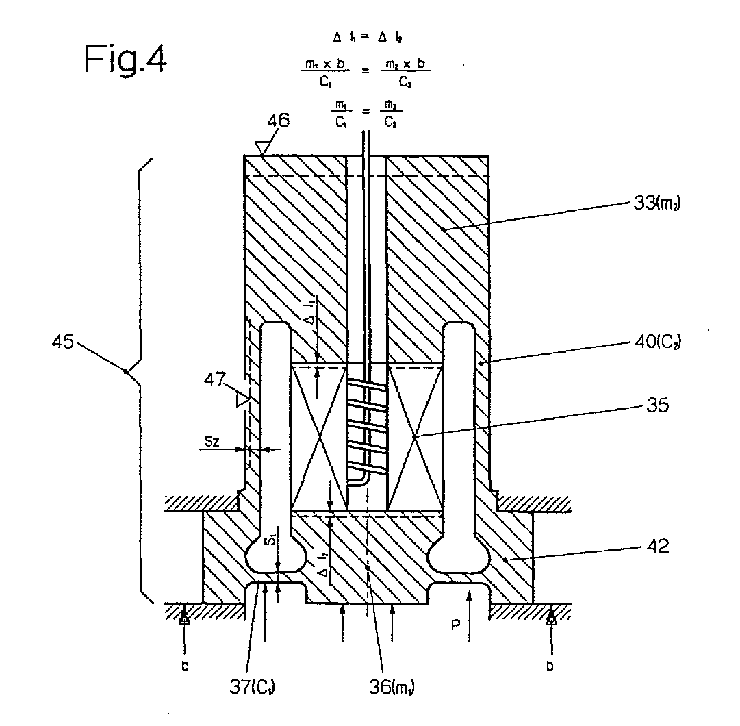
- Fig. 4 inner part of the pressure transducer according to the invention 3, schematically in section.
- Fig. 5 inventive piezoelectric pressure transducer, with Metal cable connection and a variant in flange welding, schematically in section.
- Fig. 6 A variant of an inner part of the pressure transducer with screwable Heavy metal mass, schematically in section.
- Fig. 7 piezoelectric pressure transducer according to the invention with variant in the membrane welding and the side support of the inner part.
- Fig. 8 piezoelectric pressure transducer according to the invention installed on shaker pliers, with direct display of fine compensation.
- Fig. 1 and Fig. 2 show piezoelectric pressure transducers as they Over the past 20 years, thousands have been built and continued to be built become.
- Fig. 1 shows the cross section of an acceleration-compensated Pressure transducer of the simpler type, where 1 is the pressure transducer housing is.
- the compensation crystal set 2 is in the form of a Piezo plate shown.
- the compensation mass 3 is an electrode formed and includes the contact spring 4.
- the measuring crystal set 5 is shown in the form of three piezo plates, respectively a well-known trading pattern.
- the membrane bottom mass 6 is the mass m1, while 3 is the mass m2 represents. These two masses are dimensioned so that an optimal Acceleration compensation is achieved.
- the membrane 7 connects the pressure transducer housing 1 provided with mounting thread 8 with the mass 6. Usually, the housing 1 by means of a sealing ring 10 sealed against the machine wall 9. With 11 is one Connector thread designated for the connection of a cable connector; 12 is a contact sleeve for receiving the plug.
- Fig. 2 shows a more complicated form of a piezoelectric Pressure converter, as it is used primarily in turbines.
- the Compensation mass 23 is by means of screw 28 with the diaphragm bottom mass 26 connected, which via the membrane 27 to the housing 21 is connected.
- the measuring crystal set 25 consists of a plurality of piezo disks, the signals of which are by means of metal electrodes be removed.
- the opposite compensation crystal set 22 is shown with two piezo plates, between an electrode with the signal line leading to the connector connected is. When the cover 29 is open, the compensation mass 23 can be adjusted in the fully assembled state, what about 1 is an advantage.
- FIG. 3 schematically shows a pressure sensor according to the invention with dynamic compensation, without additional downstream Crystal set.
- the housing outer part 31 surrounds the inner part 45, consisting of the overlay compensation mass 33, the measuring crystal set 35 and the membrane bottom mass 36, which over the membrane 37 is connected to the flange 42.
- the inner wall sleeve 40 the can also be replaced by individual bars, the compensation mass binds 33 also on the flange 42. This creates a closed Unit in which the enclosed crystal set 35 under mechanical preload.
- the inner part 45 is after Coarse or fine compensation of the acceleration sensitivity in inserted the housing outer part 31 and by means of welding 41 connected to this via the flange 42.
- the measuring system which is housed in the inner part 45, can swing freely in the axial direction, since it never touches the housing wall 31 touched.
- the measuring crystal set 35 here consists of transverse cut crystal elements, in the middle of which the contact spring 34 elastic the signal lead to the connector. As shown in Fig. 6, a crystal set consisting of longitudinally cut or ceramic piezo plates, use Find.
- Membrane 37 and inner wall sleeve 40 are determined as spring elements Stiffness acting connecting elements between the masses 36 (m1) and 33 (m2) as well as the flange 42. Their stiffness c1 or c2 can be adjusted by material removal if necessary, around, as shown below, in connection with a vote the masses m1 and m2 a compensation of acceleration and To cause vibrational forces. However, there is an intervention on the membrane 37, which also have a certain minimum stiffness must, is relatively difficult, material is removed for coordination of stiffness preferably on the inner wall sleeve 40.
- the inner part 45 hangs freely at the clamping point of the flange 42, at which the measuring system is clamped onto the shaker, as indicated. If an acceleration b now acts on the flange 42 from below, it covers a certain distance upwards per unit of time. Due to their inertia and the "suspension" of the elements 37 and 40, the masses 36 and 33 each experience a micro-displacement ⁇ l 2 or ⁇ l 1 relative to the flange 42 and to the housing outer part 31 connected to it downwards.
- the acceleration b does not generate a measurement signal in the crystal set, since this is not loaded.
- a medium pressure p on the diaphragm bottom mass 36 and the diaphragm 37 produces an upward displacement, which, however, is practically not passed on through the inner wall sleeve 40, but is instead mounted in the flange 42. If the support compensation mass 33 does not move, a measurement signal is produced by compressing the crystal set 35.
- the stiffnesses c1 and c2 and / or the masses 33 and 36 can be in a selected frequency range in this way acceleration compensation, without additional separate set of crystals.
- the selected frequency range is appropriately defined so that it covers the measuring range of the pressure sensor 31 largely covered. So that's one significant constructive simplification possible and thus also a economic progress achieved. But is very special any influence of external forces on the connector and housing 31 minimized.
- the reason for a minimum stiffness c1 of the membrane 37 is that the support compensation mass 33 cannot be made arbitrarily large, which yes, 4, to the mass 36 (ml) and the stiffnesses c1 and c2 must be in a certain relation. Furthermore should the stiffness c2 of the inner wall sleeve 40 is as great as due to the 4 relationship made possible to forwarding a medium pressure load to be measured on the mass 33 as far as possible. This can reduce sensitivity of the pressure force transducer according to the invention optimized become.
- FIG. 5 shows a further pressure transducer 51 according to the invention, with design variants.
- a plug connection is a Metal cable 52 via the welding flange 53 to the pressure sensor 51 integrated.
- the seal 10 attached under the hex, which is a solid threaded part 48 follows.
- the inner part 45 with the flange 42 is with the threaded part 48, connected by welding 44, frontally. This type is preferred for low pressure application.
- Fig. 6 shows a variant of an inner part 45.
- an additional mass 60 is applied to the support compensation mass 33, e.g. with a thread 61, in the case of a material, that is not weldable, e.g. a tungsten-based heavy metal.
- a plate crystal set 62 shown made of ceramic piezoplates or Single crystal plates exist. The signal must be picked up accordingly be designed from the top plate.
- FIG. 7 shows further variants of designs according to the invention.
- the membrane 77 is connected to the flange by means of frontal welding 78 42 connected.
- a lateral deflection of the compensation mass 33 by a on the right side indicated transverse support membrane 76, which is clamped in the separating part 75 by means of welding 74 is.
- Fig. 8 shows the process of fine-tuning before the acceptance test.
- the pressure sensor with connection line is on the compensation display device 86 connected and with its outer housing part 81 in the clamping sleeve 83 of the shaker, by means of a threaded sleeve 82, assembled.
- step by step with milling or grinding tools 85 Material from the fine compensation trough 84 of the membrane base mass 36 removed until the display device 86, when switched on Shaker that gives optimal value. This allows all pressure transducers a series on specified values of acceleration compensation to be brought.
Landscapes
- Physics & Mathematics (AREA)
- General Physics & Mathematics (AREA)
- Measuring Fluid Pressure (AREA)
- Paper (AREA)
Abstract
Zur Messung von dynamischen Vorgängen in gasförmigen und flüssigen Medien, z.B. in Motoren und Turbo-Systemen, sind Druckaufnehmer gefragt, welche in die vibrierenden Gehäusewände solcher Maschinen montiert werden können, ohne dass sie deren Beschleunigungskräfte ins Drucksignal einstreuen. In vielen Fällen können Verbesserungen erzielt werden durch elastische oder dämpfende Einbau-Adapter. Besser ist es jedoch, die Beschleunigungskräfte durch integrierte Gegenmassnahmen, die direkt auf das Messsignal wirken, zu kompensieren. Dem Stand der Technik entsprechend wurde dazu ein zweiter Kristallsatz mit einer Zusatzmasse so ins Messsignal eingeschaltet, dass bei Beschleunigung ein Gegensignal vom Drucksignal subtrahiert wurde.For measuring dynamic processes in gaseous and liquid Media, e.g. in engines and turbo systems, are pressure transducers asked which in the vibrating housing walls of such machines can be mounted without their acceleration forces strew in the pressure signal. In many cases, improvements can be made can be achieved with elastic or damping built-in adapters. However, it is better to use the acceleration forces through integrated To compensate for countermeasures that act directly on the measurement signal. In accordance with the state of the art, a second one was added Crystal set with an additional mass switched into the measurement signal so that a counter signal is subtracted from the pressure signal during acceleration has been.
Erfindungsgemäss kann dieselbe Kompensationswirkung mit nur dem
Signalkristallsatz 35 erreicht werden, indem die beiden Massen [36
(m1)] und [33(m2)]zu einem geschlossenen Element verbunden werden
und am Einbauende, mittels Flansch 42, gehalten sind. Das Einbaugehäuse
des Druckaufnehmers wird an diese Flanschpartie 42 angeschweisst
und berührt den Innenteil 45 des Druckaufnehmers an keiner
anderen Stelle mehr. Damit ist der Innenteil 45 als frei
schwingendes Element ausgebildet, das bei Optimierung der Massen
(m1,m2) und der Federsteifigkeiten (c1,c2) nur das Drucksignal
misst. Damit kann ein wesentlich vereinfachtes Messsystem gebaut
werden, mit nur einem Messkristallsatz (35).
Description
Die Erfindung betrifft einen beschleunigungskompensierten Druckaufnehmer
gemäss Oberbegriff von Anspruch 1.The invention relates to an acceleration-compensated pressure sensor
according to the preamble of
Für die Messung dynamischer Druckvorgänge in gasförmigen oder flüssigen Medien, insbesondere an Motoren und Turbo-Systemen, sind Druckaufnehmer gefragt, welche direkt in die vibrierenden Gehäusewände solcher Maschinen montiert werden können, ohne dass sie deren Beschleunigungskräfte in das zu messende Drucksignal einstreuen. Üblicherweise werden für solche Messungen piezoelektrische Druckaufnehmer verwendet, besonders wenn es sich um hochdynamische Vorgänge oder um Messungen in Temperaturbereichen von über 200°C handelt.For the measurement of dynamic pressure processes in gaseous or liquid media, especially on engines and turbo systems Pressure transducers asked which ones directly in the vibrating housing walls such machines can be assembled without them sprinkle their acceleration forces into the pressure signal to be measured. Piezoelectric are usually used for such measurements Pressure transducer used, especially when it is highly dynamic Processes or to take measurements in temperature ranges above 200 ° C.
In einzelnen Anwendungsfällen genügt es, wenn die Druckaufnehmer mittels elastisch gelagerten Adaptern in die vibrierenden Maschinenwände eingebaut werden. In höheren Temperaturbereichen ist dies meist nicht möglich, so dass zur separaten Erfassung der Beschleunigungkräfte seit Jahren piezoelektrische Beschleunigungselemente in die Druckaufnehmer integriert werden. Dazu ist ein hoher technischer Aufwand nötig, weil ein zusätzliches Piezoelement, meist in Form von einer oder mehreren Kristallplatten, in Gegenschaltung zum Drucksignal-Kristallsatz, eingebaut werden muss. Dadurch reduziert sich das Nutzdrucksignal um mindestens 1/3 des Maximalwertes, was ein weiterer grosser Nachteil ist, weil in vielen Fällen Amplituden von wenigen Millibar gemessen werden müssen. Zudem hat sich gezeigt, dass die mit den bekannten Gegenmitteln erreichte Beschleunigungskompensation sehr stark beeinflusst werden kann, durch Stecker- oder Metallkabelanschlüsse, d.h. wenn zusätzliche Massen an das Druckaufnehmergehäuse angeschlossen werden.In individual applications, it is sufficient if the pressure transducer into the vibrating machine walls by means of elastically mounted adapters to be built in. This is in higher temperature ranges mostly not possible, so that the acceleration forces are recorded separately Piezoelectric accelerators for years can be integrated into the pressure transducer. This is a high level of technical Effort needed because an additional piezo element, usually in the form of one or more crystal plates, in reverse connection to the pressure signal crystal set, must be installed. This reduces the useful pressure signal is at least 1/3 of the maximum value, which is another big disadvantage because in many cases Amplitudes of a few millibars must be measured. In addition has been shown to achieve that with the known antidotes Acceleration compensation can be influenced very strongly, through plug or metal cable connections, i.e. if additional Masses are connected to the pressure transducer housing.
Aufgabe der Erfindung ist es, Druckaufnehmer der genannten Art
technisch zu vereinfachen und den Einflüssen der verschiedenen Anschlussmethoden
zu entziehen. Diese Aufgabe wird mittels der Merkmale
im Kennzeichen von Anspruch 1 gelöst. Durch die Aufteilung
des Druckaufnehmers in einen messenden Innenteil und einem gehäuseartigen
Aussenteil, die beide nur an der Membran-Flanschpartie
miteinander verbunden sind, wird ein frei schwingendes Mess-System
erhalten, das unabhängig vom Einbaugehäuse misst, schwingt und Beschleunigungen
und Vibrationen kompensiert, wie später noch erläutert
wird anhand von Fig. 4.The object of the invention is to pressure transducers of the type mentioned
technically simplified and the influences of the different connection methods
to withdraw. This task is accomplished through the characteristics
solved in the characterizing part of
Im Folgenden wird die Erfindung anhand von Ausführungsbeispielen im Zusammenhang mit der Zeichnung näher erläutert.In the following, the invention is illustrated using exemplary embodiments explained in connection with the drawing.
Es zeigen:Show it:
Fig. 1 State of the Art piezoelektrische Druckaufnehmer, mit zwei in Serie gegeneinander geschalteten Kristallsätzen, schematisch im Schnitt.Fig. 1 State of the art piezoelectric pressure transducer, with two crystal sets connected in series against each other, schematically in Cut.
Fig. 2 State of the Art piezoelektrische Druckaufnehmer, mit zwei Kristallsätzen, die ebenfalls gegeneinander geschaltet sind, und dessen Masse m2 bearbeitbar ist.Fig. 2 State of the art piezoelectric pressure transducer, with two Crystal sets, which are also connected to each other, and whose mass m2 is editable.
Fig. 3 Erfindungsgemässer piezoelektrischer Druckaufnehmer, schematisch im Schnitt.3 piezoelectric pressure transducer according to the invention, schematically in section.
Fig. 4 Erfindungsgemässer Innenteil des Druckaufnehmers
nach Fig. 3, schematisch im Schnitt.Fig. 4 inner part of the pressure transducer according to the
Fig. 5 Erfindungsgemässer piezoelektrischer Druckaufnehmer, mit Metallkabelanschluss und einer Variante in der Flansch-Schweissung, schematisch im Schnitt.Fig. 5 inventive piezoelectric pressure transducer, with Metal cable connection and a variant in flange welding, schematically in section.
Fig. 6 Eine Variante eines Innenteils des Druckaufnehmers mit aufschraubbarer Schwermetallmasse, schematisch im Schnitt.Fig. 6 A variant of an inner part of the pressure transducer with screwable Heavy metal mass, schematically in section.
Fig. 7 Erfindungsgemässer piezoelektrischer Druckaufnehmer mit Variante in der Membranschweissung und der Seitenabstützung des Innenteils.Fig. 7 piezoelectric pressure transducer according to the invention with variant in the membrane welding and the side support of the inner part.
Fig. 8 Erfindungsgemässer piezoelektrischer Druckaufnehmer, eingebaut auf Shakerzange, mit Direktanzeige der Feinkompensation. Fig. 8 piezoelectric pressure transducer according to the invention, installed on shaker pliers, with direct display of fine compensation.
Fig. 1 und Fig. 2 zeigen piezoelektrische Druckaufnehmer, wie sie in den letzten 20 Jahren zu Tausenden gebaut wurden und weiter gebaut werden.Fig. 1 and Fig. 2 show piezoelectric pressure transducers as they Over the past 20 years, thousands have been built and continued to be built become.
Fig 1 zeigt den Querschnitt eines beschleunigungs-kompensierten
Durckaufnehmers der einfacheren Art, wobei 1 das Druckaufnehmer-Gehäuse
ist. Der Kompensations-Kristallsatz 2 ist in Form einer
Piezoplatte gezeigt. Die Kompensationsmasse 3 ist als Elektrode
ausgebildet und schliesst die Kontaktfeder 4 ein. Der Mess-Kristallsatz
5 ist in Form von drei Piezoplatten gezeigt, entsprechend
einem bekannten Handelsmuster.Fig. 1 shows the cross section of an acceleration-compensated
Pressure transducer of the simpler type, where 1 is the pressure transducer housing
is. The
Die Membranbodenmasse 6 ist die Masse m1, während 3 die Masse m2
darstellt. Diese beiden Massen sind so bemessen, dass eine optimale
Beschleunigungskompensation erreicht wird. Die Membrane 7 verbindet
das mit Montagegewinde 8 versehene Druckaufnehmergehäuse 1
mit der Masse 6. Üblicherweise wird das Gehäuse 1 mittels Dichtring
10 gegen die Maschinenwand 9 abgedichtet. Mit 11 ist ein
Steckergewinde für den Anschluss eines Kabelsteckers bezeichnet;
12 ist eine Kontakthülse für die Aufnahme des Steckers.The
Fig. 2 zeigt eine kompliziertere Form eines piezoelektrischen
Druckwandlers, wie er vor allem in Turbinen verwendet wird. Die
Kompensationsmasse 23 ist mittels Schraube 28 mit der Membranbodenmasse
26 verbunden, welche über die Membrane 27 mit dem Gehäuse
21 verbunden ist. Der Mess-Kristallsatz 25 besteht aus einer Mehrzahl
von Piezoscheiben, deren Signale seitlich mittels Metallelektroden
abgenommen werden. Der entgegengeschaltete Kompensations-Kristallsatz
22 ist mit zwei Piezoplatten dargestellt, zwischen
denen eine Elektrode mit der Signalleitung, die zum Stecker führt,
verbunden ist. Bei geöffnetem Deckel 29 kann die Kompensationsmasse
23 im fertig montierten Zustand angepasst werden, was gegenüber
Fig. 1 ein Vorteil ist.Fig. 2 shows a more complicated form of a piezoelectric
Pressure converter, as it is used primarily in turbines. The
Fig. 3 zeigt schematisch einen erfindungsgemässen Druckaufnehmer
mit dynamischer Kompensation, ohne zusätzlich nachgeschalteten
Kristallsatz. Der Gehäuseaussenteil 31 umgibt den Innenteil 45,
bestehend aus der Auflage-Kompensationsmasse 33, dem Mess-Kristallsatz
35 und der Membranbodenmasse 36, die über die Membrane
37 mit dem Flansch 42 verbunden ist. Die Innenwandhülse 40, die
auch durch einzelne Stege ersetzt sein kann, bindet die Kompensationsmasse
33 ebenfalls an den Flansch 42. So entsteht eine geschlossene
Einheit, in der der eingeschlossene Kristallsatz 35 unter
mechanischer Vorspannung steht. Der Innenteil 45 wird nach
Grob- oder Feinkompensation der Beschleunigungs-Empfindlichkeit in
den Gehäuseaussenteil 31 eingesteckt und mittels Schweissung 41
mit diesem über den Flansch 42 verbunden. Damit ist die Membranpartie
37 fest mit dem Gehäuseaussenteil 31 und somit über das
Montagegewinde 38 mit der Maschinenwand 39 der Einbaustelle verbunden.
Das Mess-System, das im Innenteil 45 untergebracht ist,
kann in axialer Richtung frei schwingen, da er nirgends die Gehäusewand
31 berührt. Der Messkristallsatz 35 besteht hier aus transversal
geschnittenen Kristallelementen, in deren Mitte die Kontaktfeder
34 elastisch die Signalableitung zum Stecker besorgt.
Wie in Fig. 6 gezeigt, kann auch ein Kristallsatz, bestehend aus
longitudinal geschnittenen oder keramischen Piezoplatten, Verwendung
finden.3 schematically shows a pressure sensor according to the invention
with dynamic compensation, without additional downstream
Crystal set. The housing
Membrane 37 und Innenwandhülse 40 sind als Federelemente bestimmter
Steifigkeit wirkende Verbindungselemente zwischen den Massen
36(m1) und 33(m2) sowie dem Flansch 42. Ihre Steifigkeit c1 bzw.
c2 können gegebenenfalls durch Materialabtrag abgestimmt werden,
um, wie nachstehend gezeigt, in Verbindung mit einer Abstimmung
der Massen m1 und m2 eine Kompensation von Beschleunigungs- und
Vibrationskräften zu bewirken. Da jedoch ein Eingriff an der Membrane
37, die darüber hinaus eine gewisse Mindeststeifgkeit haben
muss, relativ schwierig ist, erfolgt ein Materialabtrag zur Abstimmung
der Steifigkeiten vorzugsweise an der Innenwandhülse 40.
Fig. 4 zeigt das Grundkonzept des neuen erfindungsgemässen dynamisch
kompensierten Messteils. Der Innenteil 45 hängt frei an der
Einspannstelle des Flansches 42, an welchem das Mess-System auf
den Shaker gespannt wird, wie angedeutet. Wirkt nun eine Beschleunigung
b von unten auf den Flansch 42, so legt dieser einen gewissen
Weg nach oben pro Zeiteinheit zurück. Dabei erfahren die Massen
36 und 33 aufgrund ihrer Trägheit und der "Federung" der Elemente
37 und 40 je eine Mikroverdrängung Δl2 bzw. Δl1 relativ zum
Flansch 42 und zu dem mit ihm verbundenen Gehäuse-Aussenteil 31
nach unten. Werden nun die Werte der Grössen m1,m2,c1,c2 erfindungsgemäss
so aufeinander abgestimmt, dass Δl1 = Δl2 (Fig. 4)
ist, dann erzeugt die Beschleunigung b kein Messsignal im Kristallsatz,
da dieser nicht belastet wird. Dagegen erzeugt ein Mediumdruck
p auf die Membranbodenmasse 36 und die Membrane 37 eine
Verdrängung nach oben, die aber durch die Innenwandhülse 40 praktisch
nicht weitergeleitet wird, sondern im Flansch 42 gelagert
ist. Durch Nichtbewegung der Auflage-Kompensationsmasse 33 entsteht
somit durch Kompression des Kristallsatzes 35 ein Messsignal.4 shows the basic concept of the new dynamically compensated measuring part according to the invention. The
Durch geeignete Abstimmung der Steifigkeiten c1 und c2 und/oder
der Massen 33 bzw. 36 kann in einem ausgewählten Frequenzbereich
auf diese Weise eine Beschleunigungs-Kompensation, ohne zusätzlichen
separaten Kristallsatz, erreicht werden. Der ausgewählte Frequenzbereich
wird zweckmässig so definiert, dass er den Messbereich
des Druckaufnehmers 31 weitgehend überdeckt. Damit ist eine
wesentliche konstruktive Vereinfachung möglich und somit auch ein
wirtschaftlicher Fortschritt erreicht. Ganz besonders ist aber
auch jeder Einfluss von äusseren Kräften auf Stecker und Gehäuse
31 minimiert.By appropriate coordination of the stiffnesses c1 and c2 and / or
the
Ergänzend sei noch erwähnt, dass der Grund für eine Mindeststeifigkeit
c1 der Membrane 37 darin besteht, dass die Auflage-Kompensationsmasse
33 nicht beliebig gross gemacht werden kann, die ja,
wie in Fig. 4 gezeigt, zur Masse 36 (ml) und den Steifgkeiten c1
und c2 in einer bestimmten Relation stehen muss. Weiterhin sollte
die Steifigkeit c2 der Innenwandhülse 40 so gross wie aufgrund der
in Fig. 4 gezeigten Beziehung möglich gemacht werden, um eine Weiterleitung
einer zu messenden Mediumdruck-Belastung auf die Masse
33 so weit wie möglich zu unterbinden. Dadurch kann die Empfindlichkeit
des erfindungsgemässen Druckkraftaufnehmers optimiert
werden. In addition, it should be mentioned that the reason for a minimum stiffness
c1 of the
Fig. 5 zeigt einen weiteren erfindungsgemässen Druckaufnehmer 51,
mit Ausführungsvarianten. Anstelle einer Steckerverbindung ist ein
Metallkabel 52 über den Schweissflansch 53 mit dem Druckaufnehmer
51 integriert. Anstelle der Frontdichtung von Fig. 3 ist die Dichtung
10 unter dem 6-Kant angebracht, dem ein massiver Gewindeteil
48 folgt. Der Innenteil 45 mit dem Flansch 42 ist mit dem Gewindeteil
48, mittels Schweissung 44, frontal verbunden. Diese Bauart
wird für Niederdruck-Anwendung bevorzugt.5 shows a
Fig. 6 zeigt eine Variante eines Innteils 45. Um Platz zu sparen,
ist eine Zusatzmasse 60 auf der Auflage-Kompensationsmasse 33 aufgebracht,
z.B. mit einem Gewinde 61, für den Fall eines Materials,
das nicht schweissbar ist, wie z.B. ein Schwermetall auf Wolframbasis.
Anstelle des Transversal-Kristallsatzes 35, ist ein Platten-Kristallsatz
62 gezeigt, der aus keramischen Piezoplatten oder
Einkristallplatten besteht. Entsprechend muss die Signalabnahme
von der obersten Platte aus gestaltet sein.Fig. 6 shows a variant of an
Fig. 7 zeigt weitere Varianten erfindungsgemässer Ausführungen.
Die Membrane 77 ist mittels Frontal-Schweissung 78 mit dem Flansch
42 verbunden. In Einbauten, wo hohe Seitenbeschleunigungen wirken,
ist ein seitliches Auslenken der Kompensationsmasse 33 durch eine
auf der rechten Seite angedeuteten Querabstützmembrane 76 erschwert,
die im Trennteil 75 mittels Schweissung 74 eingeklemmt
ist.7 shows further variants of designs according to the invention.
The
Fig. 8 zeigt das Verfahren der Feinabstimmung vor der Abnahmeprüfung.
Dazu ist der Druckaufnehmer mit Anschlussleitung am Kompensations-Anzeigegeräts
86 angeschlossen und mit seinem Gehäuse-Aussenteil
81 in der Spannhülse 83 des Shakers, mittels Gewindehülse
82, montiert. Schrittweise wird nun mit Fräs- oder Schleifwerkzeug
85 Material aus der Feinkompensationsmulde 84 der Membranbodenmasse
36 abgetragen, bis das Anzeigegerät 86, bei eingeschaltetem
Shaker, den Optimalwert ergibt. Damit können alle Druckaufnehmer
einer Serie auf spezifizierte Werte der Beschleunigungs-Kompensation
gebracht werden.Fig. 8 shows the process of fine-tuning before the acceptance test.
For this purpose, the pressure sensor with connection line is on the
Die Erfindung ermöglicht somit einen bedeutenden Fortschritt durch
eine wesentliche konstruktive Vereinfachung sowie durch völlige
Unabhängigkeit des Kompensationsgrads von äusseren Krafteinflüssen
auf das Druckaufnehmergehäuse, z.B. durch Kabel verschiedener Längen,
die eigene Schwingungen einleiten können.
- 1
- Druckaufnehmer-Gehäuse
- 2
- Kompensations-Kristallsatz
- 3
- Kompensationsmasse m2
- 4
- Kontaktfeder
- 5
- Mess-Kristallsatz
- 6
- Membranbodenmasse m1
- 7
- Membrane
- 8
- Montagegewinde
- 9
- Maschinenwand
- 10
- Dichtring
- 11
- Steckergewinde
- 12
- Kontakthülse
- 21
- Druckaufnehmer-Gehäuse
- 22
- Kompensations-Kristallsatz
- 23
- Kompensationsmasse m2
- 25
- Mess-Kristallsatz
- 26
- Membranbodenmasse m1
- 27
- Membrane
- 28
- Schraube
- 29
- Deckel
- 31
- Druckaufnehmer-Gehäuseaussenteil
- 33
- Auflage-Kompensationsmasse m2
- 34
- Kontaktfeder
- 35
- Mess-Kristallsatz, Transversaltyp
- 36
- Membranbodenmasse m1
- 37
- Membrane
- 38
- Montagegewinde
- 39
- Maschinenwand
- 40
- Innenwandhülse
- 41
- Schweissung, radial
- 42
- Flansch
- 43
- Dichtring
- 45
- Innenteil bestehend aus:
- 33
- Auflage-Kompensationsmasse m2
- 40
- Innenwandhülse mit Steifigkeit C2
- 36
- Membranbodenmasse m1
- 37
- Membrane mit Steifigkeit C1
- 35
- Mess-Kristallsatz, transversal
- b
- Beschleunigungsvektor
- p
- Mediumdruck
- Δl1
- Mikroverdrängung
- Δl2
- Mikroverdrängung
- 46
- Abtragstelle Masse m2
- 47
- Abtragstelle Innenwandhülse zur Veränderung der Steifigkeit C2
- 51
- Druckaufnehmer Gehäuseaussenteil
- 52
- Metallkabel
- 53
- Schweissflansch
- 45
- Druckaufnehmer Innenteil
- 42
- Flansch, Verbindung Innenteil-Aussenteil
- 44
- Schweissung frontal
- 48
- Gewindeteil
- 45
- Innenteil
- 60
- Zusatzmasse
- 61
- Aufschraubgewinde
- 62
- Mess-Kristallsatz, longitudinal Platten
- 79
- Membranträger
- 76
- Querabstützmembran
- 75
- Deckel
- 74
- Schweissung
- 77
- Membran
- 78
- Frontal-Schweissung
- 43
- Dichtring
- 81
- Druckaufnehmer-Gehäuseaussenteil
- 82
- Gewindehülse
- 83
- Spannhülse des Shakers
- 84
- Feinkompensationsmulde in Membranbodenmasse ml
- 85
- Fräs- oder Schleifwerkzeug
- 86
- Kompensations-Anzeige-Gerät
- 1
- Pressure sensor housing
- 2nd
- Compensation crystal set
- 3rd
- Compensation mass m2
- 4th
- Contact spring
- 5
- Measuring crystal set
- 6
- Membrane soil mass m1
- 7
- membrane
- 8th
- Mounting thread
- 9
- Machine wall
- 10th
- Sealing ring
- 11
- Connector thread
- 12th
- Contact sleeve
- 21
- Pressure sensor housing
- 22
- Compensation crystal set
- 23
- Compensation mass m2
- 25th
- Measuring crystal set
- 26
- Membrane soil mass m1
- 27
- membrane
- 28
- screw
- 29
- cover
- 31
- Pressure sensor housing outer part
- 33
- Pad compensation mass m2
- 34
- Contact spring
- 35
- Measuring crystal set, transversal type
- 36
- Membrane soil mass m1
- 37
- membrane
- 38
- Mounting thread
- 39
- Machine wall
- 40
- Inner wall sleeve
- 41
- Radial welding
- 42
- flange
- 43
- Sealing ring
- 45
- Inner part consisting of:
- 33
- Pad compensation mass m2
- 40
- Inner wall sleeve with stiffness C2
- 36
- Membrane soil mass m1
- 37
- Membrane with C1 stiffness
- 35
- Measuring crystal set, transversal
- b
- Acceleration vector
- p
- Medium pressure
- Δl 1
- Micro displacement
- Δl 2
- Micro displacement
- 46
- Ablation point mass m2
- 47
- Removal point of inner wall sleeve to change the stiffness C2
- 51
- Pressure transducer outer part
- 52
- Metal cable
- 53
- Welding flange
- 45
- Pressure sensor inner part
- 42
- Flange, connection between inner part and outer part
- 44
- Frontal welding
- 48
- Threaded part
- 45
- inner part
- 60
- Additional mass
- 61
- Screw thread
- 62
- Measuring crystal set, longitudinal plates
- 79
- Membrane support
- 76
- Cross support membrane
- 75
- cover
- 74
- Welding
- 77
- membrane
- 78
- Frontal welding
- 43
- Sealing ring
- 81
- Pressure sensor housing outer part
- 82
- Threaded sleeve
- 83
- Adapter sleeve of the shaker
- 84
- Fine compensation trough in membrane soil mass ml
- 85
- Milling or grinding tool
- 86
- Compensation display device
Claims (11)
Applications Claiming Priority (3)
| Application Number | Priority Date | Filing Date | Title |
|---|---|---|---|
| CH2171/97 | 1997-09-15 | ||
| CH02171/97A CH691625A5 (en) | 1997-09-15 | 1997-09-15 | Acceleration compensated pressure purchase taker. |
| CH217197 | 1997-09-15 |
Publications (3)
| Publication Number | Publication Date |
|---|---|
| EP0902267A2 true EP0902267A2 (en) | 1999-03-17 |
| EP0902267A3 EP0902267A3 (en) | 1999-09-22 |
| EP0902267B1 EP0902267B1 (en) | 2003-06-11 |
Family
ID=4227555
Family Applications (1)
| Application Number | Title | Priority Date | Filing Date |
|---|---|---|---|
| EP98810812A Expired - Lifetime EP0902267B1 (en) | 1997-09-15 | 1998-08-20 | Pressure transducer with compensation for acceleration effects |
Country Status (6)
| Country | Link |
|---|---|
| US (1) | US6105434A (en) |
| EP (1) | EP0902267B1 (en) |
| JP (1) | JP3718063B2 (en) |
| AT (1) | ATE242874T1 (en) |
| CH (1) | CH691625A5 (en) |
| DE (1) | DE59808678D1 (en) |
Cited By (8)
| Publication number | Priority date | Publication date | Assignee | Title |
|---|---|---|---|---|
| EP0992779B1 (en) * | 1998-10-06 | 2003-05-21 | Vibro-Meter Sa | Acceleration compensated pressure measuring device |
| WO2006131015A3 (en) * | 2005-06-10 | 2007-02-22 | Kistler Holding Ag | Pressure sensor with active and passive acceleration compensation |
| AT504485B1 (en) * | 2006-11-22 | 2008-06-15 | Piezocryst Advanced Sensorics | PIEZOELECTRIC PRESSURE SENSOR |
| WO2009101566A1 (en) * | 2008-02-15 | 2009-08-20 | Koninklijke Philips Electronics N.V. | Compensating pressure sensor measurements |
| EP2993454A4 (en) * | 2013-11-25 | 2017-01-04 | Horiba Stec, Co., Ltd. | Capacitive pressure sensor |
| CN111664989A (en) * | 2020-06-16 | 2020-09-15 | 马鞍山市亿格仪表有限公司 | A shock-resistant automatic reset pressure gauge and its installation method |
| CN114323364A (en) * | 2021-11-11 | 2022-04-12 | 浙江中控技术股份有限公司 | High-precision pressure sensor with vibration measurement function and correction method |
| EP4102202A2 (en) | 2021-06-11 | 2022-12-14 | Kistler Holding AG | Transducer element |
Families Citing this family (13)
| Publication number | Priority date | Publication date | Assignee | Title |
|---|---|---|---|---|
| EP1134588A1 (en) | 2000-03-08 | 2001-09-19 | Vibro-Meter Sa | Piezo-electric accelerometer with lateral stabilising element |
| US6684700B1 (en) * | 2000-08-11 | 2004-02-03 | Swantech, L.L.C. | Stress wave sensor |
| SI1792155T1 (en) * | 2004-09-22 | 2012-08-31 | Kistler Holding Ag | Pressure sensor |
| AT503664B1 (en) * | 2006-04-13 | 2007-12-15 | Piezocryst Advanced Sensorics | PIEZOELECTRIC PRESSURE SENSOR |
| JP4840098B2 (en) | 2006-11-20 | 2011-12-21 | トヨタ自動車株式会社 | Pressure sensor |
| DK2095085T3 (en) * | 2006-12-11 | 2017-03-27 | Kistler Holding Ag | ADAPTER TO PRESSURE SENSORS |
| JP5184052B2 (en) * | 2007-11-08 | 2013-04-17 | シチズンファインテックミヨタ株式会社 | Combustion pressure sensor |
| DE102008001523A1 (en) * | 2008-04-30 | 2009-11-05 | Robert Bosch Gmbh | threaded connector |
| CH702257A1 (en) * | 2009-11-25 | 2011-05-31 | Kistler Holding Ag | Pressure sensor. |
| WO2017093100A1 (en) | 2015-12-04 | 2017-06-08 | Kistler Holding Ag | Acceleration measuring device and method for the production of an acceleration measuring device of said type |
| CN108291926B (en) | 2015-12-04 | 2020-08-07 | 基斯特勒控股公司 | Accelerometer and method of making the same |
| JP2019012012A (en) * | 2017-06-30 | 2019-01-24 | セイコーエプソン株式会社 | Force detection device and robot |
| ES2847550T3 (en) | 2018-02-28 | 2021-08-03 | Kistler Holding Ag | Communication system for data transmission between data sources and data evaluators |
Family Cites Families (14)
| Publication number | Priority date | Publication date | Assignee | Title |
|---|---|---|---|---|
| AT269515B (en) * | 1967-02-20 | 1969-03-25 | H C Hans Dipl Ing Dr Dr List | Piezoelectric transducer with acceleration compensation |
| GB1194074A (en) * | 1968-05-23 | 1970-06-10 | Elektronikai Es Finommechanika | Punched Tape-Feed Mechanism |
| US3602744A (en) * | 1969-06-11 | 1971-08-31 | Kistler Instr Corp | Welded pressure transducer |
| CH509580A (en) * | 1969-06-20 | 1971-06-30 | Kistler Instrumente Ag | Pressure transducer |
| US3651353A (en) * | 1969-10-13 | 1972-03-21 | Sundstrand Data Control | Piezoelectric pressure transducer with acceleration compensation |
| CH537013A (en) * | 1972-05-08 | 1973-05-15 | Kistler Instrumente Ag | Pressure transducer |
| CH582353A5 (en) * | 1974-11-08 | 1976-11-30 | Kistler Instrumente Ag | |
| EP0090872B1 (en) * | 1982-04-06 | 1986-01-15 | Kistler Instrumente AG | High pressure detector |
| ATE24764T1 (en) * | 1982-04-06 | 1987-01-15 | Kistler Instrumente Ag | HIGH PRESSURE TRANSDUCER. |
| US4604544A (en) * | 1983-10-17 | 1986-08-05 | Jeco Co., Ltd. | Piezoelectric pressure indicator |
| DE3663197D1 (en) * | 1986-01-22 | 1989-06-08 | Kristal Instr Ag | Sensor, especially for high-pressure measurements |
| DE8903667U1 (en) * | 1989-03-23 | 1989-05-11 | Kistler Instrumente Ag, Winterthur | High pressure transducer |
| JPH04131722A (en) * | 1990-09-21 | 1992-05-06 | Toyota Motor Corp | Pressure sensor and manufacture of pressure sensor |
| DE59406605D1 (en) * | 1993-10-13 | 1998-09-10 | Kk Holding Ag | Thermo-compensated pressure transducer membrane structure |
-
1997
- 1997-09-15 CH CH02171/97A patent/CH691625A5/en not_active IP Right Cessation
-
1998
- 1998-08-20 AT AT98810812T patent/ATE242874T1/en active
- 1998-08-20 DE DE59808678T patent/DE59808678D1/en not_active Expired - Lifetime
- 1998-08-20 EP EP98810812A patent/EP0902267B1/en not_active Expired - Lifetime
- 1998-09-08 US US09/149,074 patent/US6105434A/en not_active Expired - Lifetime
- 1998-09-14 JP JP26033898A patent/JP3718063B2/en not_active Expired - Lifetime
Cited By (10)
| Publication number | Priority date | Publication date | Assignee | Title |
|---|---|---|---|---|
| EP0992779B1 (en) * | 1998-10-06 | 2003-05-21 | Vibro-Meter Sa | Acceleration compensated pressure measuring device |
| WO2006131015A3 (en) * | 2005-06-10 | 2007-02-22 | Kistler Holding Ag | Pressure sensor with active and passive acceleration compensation |
| AT504485B1 (en) * | 2006-11-22 | 2008-06-15 | Piezocryst Advanced Sensorics | PIEZOELECTRIC PRESSURE SENSOR |
| WO2009101566A1 (en) * | 2008-02-15 | 2009-08-20 | Koninklijke Philips Electronics N.V. | Compensating pressure sensor measurements |
| EP2993454A4 (en) * | 2013-11-25 | 2017-01-04 | Horiba Stec, Co., Ltd. | Capacitive pressure sensor |
| US9897503B2 (en) | 2013-11-25 | 2018-02-20 | Horiba Stec, Co., Ltd. | Capacitive pressure sensor |
| CN111664989A (en) * | 2020-06-16 | 2020-09-15 | 马鞍山市亿格仪表有限公司 | A shock-resistant automatic reset pressure gauge and its installation method |
| EP4102202A2 (en) | 2021-06-11 | 2022-12-14 | Kistler Holding AG | Transducer element |
| CN114323364A (en) * | 2021-11-11 | 2022-04-12 | 浙江中控技术股份有限公司 | High-precision pressure sensor with vibration measurement function and correction method |
| CN114323364B (en) * | 2021-11-11 | 2024-01-30 | 浙江中控技术股份有限公司 | High-precision pressure sensor with vibration measuring function and correction method |
Also Published As
| Publication number | Publication date |
|---|---|
| JP3718063B2 (en) | 2005-11-16 |
| ATE242874T1 (en) | 2003-06-15 |
| US6105434A (en) | 2000-08-22 |
| EP0902267B1 (en) | 2003-06-11 |
| EP0902267A3 (en) | 1999-09-22 |
| JPH11160182A (en) | 1999-06-18 |
| DE59808678D1 (en) | 2003-07-17 |
| CH691625A5 (en) | 2001-08-31 |
Similar Documents
| Publication | Publication Date | Title |
|---|---|---|
| EP0902267B1 (en) | Pressure transducer with compensation for acceleration effects | |
| DE3741568C2 (en) | ||
| DE3878473T3 (en) | Liquid converter. | |
| DE69504665T2 (en) | ACOUSTIC CONVERTER | |
| EP0883983A1 (en) | Sensor for harvesting machines | |
| CH665904A5 (en) | DEVICE FOR DETECTING AND / OR MONITORING A PREDICTED LEVEL IN A CONTAINER. | |
| DE3930314A1 (en) | PIEZOELECTRIC SENSOR FOR MONITORING A KINETIC MOTION SIZE | |
| DE3215040A1 (en) | RESONANCE STAFF | |
| DE102006029443B3 (en) | Sensor in micromechanical design for measuring the mass flow rate according to the Coriolis principle | |
| DE4201360C2 (en) | Level measuring device | |
| DE3902604A1 (en) | ELASTIC BEARING, ESPECIALLY MOTOR VEHICLE MOTOR BEARINGS | |
| DE4113545C2 (en) | Accelerometer | |
| DE19828424C1 (en) | Micromechanical revolution rate sensor base on the Coriolis principle | |
| DE3280443T2 (en) | IMPROVED DEVICE FOR ISOLATING VIBRATION. | |
| DE3601704C2 (en) | ||
| DE3740598A1 (en) | VIBRATION UNIT FOR LEVEL VIBRATION LIMIT SWITCH | |
| DE102004045528B4 (en) | vibration sensor | |
| DE3902603A1 (en) | ELASTIC BEARING, ESPECIALLY MOTOR VEHICLE MOTOR BEARINGS | |
| WO2017071861A1 (en) | Sensor having a measurement line that can be vibrationally excited and having stiffening protrusions | |
| DE3808481C2 (en) | Device for determining a certain level in a container | |
| DE112015002785T5 (en) | Sensor for a physical size | |
| EP0763732A2 (en) | Device for material inspection of molded articles | |
| DE102019216784B3 (en) | Test device and method for assessing the noise behavior of an assembly | |
| EP1789226A1 (en) | Ultrasonic transducer comprising a sensor arranged in the mounting | |
| EP3819601A1 (en) | Coriolis mass flow meter and node element |
Legal Events
| Date | Code | Title | Description |
|---|---|---|---|
| PUAI | Public reference made under article 153(3) epc to a published international application that has entered the european phase |
Free format text: ORIGINAL CODE: 0009012 |
|
| AK | Designated contracting states |
Kind code of ref document: A2 Designated state(s): AT DE FR GB |
|
| AX | Request for extension of the european patent |
Free format text: AL;LT;LV;MK;RO;SI |
|
| PUAL | Search report despatched |
Free format text: ORIGINAL CODE: 0009013 |
|
| AK | Designated contracting states |
Kind code of ref document: A3 Designated state(s): AT BE CH CY DE DK ES FI FR GB GR IE IT LI LU MC NL PT SE |
|
| AX | Request for extension of the european patent |
Free format text: AL;LT;LV;MK;RO;SI |
|
| 17P | Request for examination filed |
Effective date: 20000306 |
|
| AKX | Designation fees paid |
Free format text: AT DE FR GB |
|
| GRAH | Despatch of communication of intention to grant a patent |
Free format text: ORIGINAL CODE: EPIDOS IGRA |
|
| 17Q | First examination report despatched |
Effective date: 20021029 |
|
| GRAH | Despatch of communication of intention to grant a patent |
Free format text: ORIGINAL CODE: EPIDOS IGRA |
|
| GRAA | (expected) grant |
Free format text: ORIGINAL CODE: 0009210 |
|
| AK | Designated contracting states |
Designated state(s): AT DE FR GB |
|
| REG | Reference to a national code |
Ref country code: GB Ref legal event code: FG4D Free format text: NOT ENGLISH |
|
| REF | Corresponds to: |
Ref document number: 59808678 Country of ref document: DE Date of ref document: 20030717 Kind code of ref document: P |
|
| RAP2 | Party data changed (patent owner data changed or rights of a patent transferred) |
Owner name: KISTLER HOLDING AG |
|
| GBT | Gb: translation of ep patent filed (gb section 77(6)(a)/1977) |
Effective date: 20031018 |
|
| ET | Fr: translation filed | ||
| PLBE | No opposition filed within time limit |
Free format text: ORIGINAL CODE: 0009261 |
|
| STAA | Information on the status of an ep patent application or granted ep patent |
Free format text: STATUS: NO OPPOSITION FILED WITHIN TIME LIMIT |
|
| 26N | No opposition filed |
Effective date: 20040312 |
|
| REG | Reference to a national code |
Ref country code: FR Ref legal event code: PLFP Year of fee payment: 19 |
|
| REG | Reference to a national code |
Ref country code: FR Ref legal event code: PLFP Year of fee payment: 20 |
|
| PGFP | Annual fee paid to national office [announced via postgrant information from national office to epo] |
Ref country code: GB Payment date: 20170822 Year of fee payment: 20 Ref country code: DE Payment date: 20170822 Year of fee payment: 20 Ref country code: FR Payment date: 20170822 Year of fee payment: 20 |
|
| PGFP | Annual fee paid to national office [announced via postgrant information from national office to epo] |
Ref country code: AT Payment date: 20170822 Year of fee payment: 20 |
|
| REG | Reference to a national code |
Ref country code: DE Ref legal event code: R071 Ref document number: 59808678 Country of ref document: DE |
|
| REG | Reference to a national code |
Ref country code: GB Ref legal event code: PE20 Expiry date: 20180819 |
|
| REG | Reference to a national code |
Ref country code: AT Ref legal event code: MK07 Ref document number: 242874 Country of ref document: AT Kind code of ref document: T Effective date: 20180820 |
|
| PG25 | Lapsed in a contracting state [announced via postgrant information from national office to epo] |
Ref country code: GB Free format text: LAPSE BECAUSE OF EXPIRATION OF PROTECTION Effective date: 20180819 |