EP0902235B1 - Arrangement for converting a conventional oil boiler to a boiler with moist, granular and solid fuel - Google Patents
Arrangement for converting a conventional oil boiler to a boiler with moist, granular and solid fuel Download PDFInfo
- Publication number
- EP0902235B1 EP0902235B1 EP98660089A EP98660089A EP0902235B1 EP 0902235 B1 EP0902235 B1 EP 0902235B1 EP 98660089 A EP98660089 A EP 98660089A EP 98660089 A EP98660089 A EP 98660089A EP 0902235 B1 EP0902235 B1 EP 0902235B1
- Authority
- EP
- European Patent Office
- Prior art keywords
- boiler
- dryer
- combustion gas
- fuel
- combustion
- Prior art date
- Legal status (The legal status is an assumption and is not a legal conclusion. Google has not performed a legal analysis and makes no representation as to the accuracy of the status listed.)
- Expired - Lifetime
Links
- 239000004449 solid propellant Substances 0.000 title claims abstract description 10
- 239000000567 combustion gas Substances 0.000 claims abstract description 37
- 239000000446 fuel Substances 0.000 claims abstract description 28
- 238000002485 combustion reaction Methods 0.000 claims abstract description 13
- 239000002245 particle Substances 0.000 claims abstract description 10
- 239000007789 gas Substances 0.000 claims abstract description 6
- 238000001035 drying Methods 0.000 claims abstract description 5
- 230000000694 effects Effects 0.000 claims description 5
- 238000012423 maintenance Methods 0.000 description 3
- 230000032258 transport Effects 0.000 description 3
- XLYOFNOQVPJJNP-UHFFFAOYSA-N water Substances O XLYOFNOQVPJJNP-UHFFFAOYSA-N 0.000 description 3
- 238000010438 heat treatment Methods 0.000 description 2
- 239000003415 peat Substances 0.000 description 2
- 238000000926 separation method Methods 0.000 description 2
- 230000006978 adaptation Effects 0.000 description 1
- 239000011362 coarse particle Substances 0.000 description 1
- 238000010276 construction Methods 0.000 description 1
- 230000007797 corrosion Effects 0.000 description 1
- 238000005260 corrosion Methods 0.000 description 1
- 239000000428 dust Substances 0.000 description 1
- 238000002474 experimental method Methods 0.000 description 1
- 239000002737 fuel gas Substances 0.000 description 1
- 239000000463 material Substances 0.000 description 1
- 239000000155 melt Substances 0.000 description 1
- 239000000203 mixture Substances 0.000 description 1
- 238000011084 recovery Methods 0.000 description 1
- 230000001172 regenerating effect Effects 0.000 description 1
- 230000001105 regulatory effect Effects 0.000 description 1
- 229910001220 stainless steel Inorganic materials 0.000 description 1
- 239000010935 stainless steel Substances 0.000 description 1
Images
Classifications
-
- F—MECHANICAL ENGINEERING; LIGHTING; HEATING; WEAPONS; BLASTING
- F23—COMBUSTION APPARATUS; COMBUSTION PROCESSES
- F23K—FEEDING FUEL TO COMBUSTION APPARATUS
- F23K1/00—Preparation of lump or pulverulent fuel in readiness for delivery to combustion apparatus
- F23K1/04—Heating fuel prior to delivery to combustion apparatus
-
- F—MECHANICAL ENGINEERING; LIGHTING; HEATING; WEAPONS; BLASTING
- F23—COMBUSTION APPARATUS; COMBUSTION PROCESSES
- F23K—FEEDING FUEL TO COMBUSTION APPARATUS
- F23K2201/00—Pretreatment of solid fuel
- F23K2201/30—Separating
-
- F—MECHANICAL ENGINEERING; LIGHTING; HEATING; WEAPONS; BLASTING
- F23—COMBUSTION APPARATUS; COMBUSTION PROCESSES
- F23K—FEEDING FUEL TO COMBUSTION APPARATUS
- F23K2900/00—Special features of, or arrangements for fuel supplies
- F23K2900/01041—Heating by using exhaust gas heat
Definitions
- the invention relates to an arrangement for converting a conventional oil boiler to a boiler with moist, granular and solid fuel, which arrangement uses a fuel combustion gas dryer connected to the boiler's combustion gas line and a combustion device for solid fuel to replace the oil burner.
- Solid fuel means here mainly sawdust, peat and other biological fuel.
- the object of the invention is to achieve a new sort of arrangement for converting a conventional oil boiler to a boiler with moist, granular and solid fuel, which gives a good efficiency and almost all the effect of the converted boiler.
- the characteristic features of the invention are presented in the accompanying patent claims.
- This invention makes use of solutions, known as such, in the way of a new combination, whereby the oil boiler can be made to function close to the optimal circumstances in a more simple way than before.
- Conventional oil boilers usually have several consecutive heat surfaces after the furnace.
- a centre tap can usually be installed somewhere in between these or even behind the furnace, for example in the maintenance hatch, whereby hot combustion gas is mixed in the desired proportion with cold combustion gases in order to obtain the desired temperature, 200 - 300°C.
- the dryer can be a dryer, known in itself, which produces fuel with a moisture level of 10 - 15% for example to be used with a CMR burner.
- CMR Chemical mechanical reactor
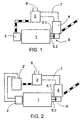
- the best application of the invention includes oil boiler 1, CMR burner 2, a fuel dryer attached to combustion gas line 6, which dryer is especially a dryer 4 with particle separator 3, in figure 1.
- the structure of the CMR burner has been explained in more detail in patent publication No 98854.
- a selective delay is created so that the coarse particles stay in the swirl chamber for a longer time and until they are smaller than of boundary size.
- the length of the flame can be made short exactly by way of only letting out particles from the burner that are smaller than of boundary size.
- a simple dryer can be made to function quite effectively when a combustion gas centre tap is fitted to the oil boiler, the duct of which has been marked with reference number 6.2 in the figure, when the usual exit duct has been marked with reference number 6.1.
- These ducts include adjustment valves by which the hot (200 - 700°C) and cold (100 - 150°C) combustion gas is mixed together in order to adjust the temperature of the drying gas.
- the humidity of the fuel for example sawdust or peat
- the temperature of the combustion gas which is fed onto the dryer 4 is 200 - 300°C and the amount of heat is enough to dry the amount of fuel of corresponding combustion capacity to a level of humidity of 10 - 15% with a moderate air surplus.
- Figure 2 presents an adaptation of the application in figure 1.
- a combination of carburetor 2' and gas burner 2 is used instead of the CMR burner in figure 1.
- the structure is more complex than that presented above, but still otherwise more advantageous than before. Also here, a great combustion capacity is obtained with dry fuel, when the water that is included in the oil does not circulate through the boiler.
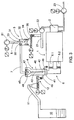
- FIG 3 presents the principle of the connection in figure 1 in more detail.
- the inner structures of dryer 4 and of particle separator 3 are presented schematically. Their most important help devices, as those of CMR burner 2 are further presented.
- a conventional oil boiler 1, of the flue - fire-tube boiler type, is equipped with a CMR burner 2 instead of an oil boiler. Its fuel supply is explained later.
- the boiler can also be a plate or pipe boiler.
- the boiler In addition to the actual combustion gas exit 6.1, the boiler has been fitted with a centre tap 6.2 in order to catch the hot combustion gas.
- the capacity of the boiler is 80 - 90% of its nominal capacity with oil.
- the temperature in the combustion gas duct 6 that leads to dryer 4 is the abovementioned 200 - 300°C.
- the moist fuel is transferred from storage silo 10 by transporter 11 via sluice feeder 12 to feed connection 48 of the dryer.
- dryer 4 The main parts of dryer 4 are: dryer pipe 40, air division chamber 41, an air division plate upon it, separator cyclone 46, which has on its upper side the tangential inlets 45, wastepipe 43 and outlet connection 49.
- the fuel is fed through the aforementioned feed connection 48 onto the air division plate 42. In case big lumps need to be removed, this is done through outlet connection 49.
- the fuel dries, it follows the strong flow upwards, arriving via the tangential feeding inlets 45 to cyclone 46, in which the heavier moist mass falls through wastepipe 43 back to air division plate 42, and the dry fuel that has circulated several times, and which is light, is let out through outlet 47.
- Outlet 47 is connected to transport duct 7 which transports the fuel-air mixture to particle separator 3 which here is formed out of cyclone 31, built on top of feeding silo 34.
- Intake connection 30 is tangential, bringing about the strong vortex that is required by the disparity.
- the bottom of cyclone 31 is slightly smaller in diameter than cone 32, the point of which shows upwards.
- the fuel particles flow along the cone surface down to the sides and further down to feeding silo 34.
- Screw transporter 35 that is included in the silo transports together with its sluice feeder the dry fuel to combustion air suction duct 21 of CMR burner 2.
- Blower 22 sucks the fuel up with the carrying airflow, and feeds it to the burner.
- the secondary airflow is produced with the help of blower 23.
- the fuel is set to be fed together with a sub-stoichiometric primary air amount into the swirl chamber and the secondary airflow is set to be fed in a concentric whirl into the swirl chamber, around the outflow.
- the rate of air is regulated with nominal effect with the help of secondary airflow to the area of 1,2 - 1,35.
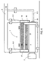
- FIG. 4 presents an arrangement in connection with a conventional oil boiler in detail.
- the oil boiler is marked with reference number 1 and it is of the flue - fire-tube boiler type. It has three passes, I, II and III, which have also been marked with reference numbers 13, 14 and 15.
- the first pass is formed by flue 13 itself.
- the second and third passes are formed by the fire-tubes.
- CMR burner 2 blows the hot combustion gases to flue 13.
- Return chamber 16 is placed at the other end, and it leads the combustion gases to the second pass 14. At the end of this, between the second pass 14 and the third pass 15, there is another return chamber 17.
- At the end of the third chamber there is an outlet chamber 18, onto which the normal combustion gas outlet connection has been fitted.
- Chambers 16, 17 and 18 are usually either provided with a maintenance hatch or they can be opened so that the fire surfaces can be cleaned.
- the abovementioned normal combustion gas duct 6.1 is connected to outlet chamber 18 connection. It is essential in relation to this invention that a centre tap 6.2 is made to the conventional boiler, which centre tap is connected to some centre chamber, here chamber 17. It would alternatively be possible to connect the centre tap also to chamber 16 by duct 6.3 which has been drawn by broken lines in the figure, for example through maintenance hatch 19, if a higher centre tap temperature were needed. Practical experiments have shown that the temperature after the second pass has been sufficient and that the required 200 - 300°C temperature is reached in all load circumstances before the dryer. Some other oil boiler might require an earlier centre tap.
- the arrangement can be fitted with a scrubber in order to further enhance the combustion gases or with a heat recovery unit in order to advance the efficiency.
Landscapes
- Engineering & Computer Science (AREA)
- Chemical & Material Sciences (AREA)
- Combustion & Propulsion (AREA)
- Mechanical Engineering (AREA)
- General Engineering & Computer Science (AREA)
- Fluidized-Bed Combustion And Resonant Combustion (AREA)
- Combustion Of Fluid Fuel (AREA)
- Liquid Carbonaceous Fuels (AREA)
- Solid Fuels And Fuel-Associated Substances (AREA)
- Drying Of Solid Materials (AREA)
Abstract
Description
- The invention relates to an arrangement for converting a conventional oil boiler to a boiler with moist, granular and solid fuel, which arrangement uses a fuel combustion gas dryer connected to the boiler's combustion gas line and a combustion device for solid fuel to replace the oil burner. Solid fuel means here mainly sawdust, peat and other biological fuel.
- Conventional heating, warm water and steam boilers which use oil are badly adaptable to solid fuel. Different pre-burner constructions are known, but they have several disadvantages. Full effect is normally not achieved, because the properties of fuel gases differ considerably from the measured values. The combustion gas temperature of a pre-burner that burns moist fuel stays much lower than that of oil heating which has been used as the standard measure. The share of water vapour is considerably greater than that measured. The situation will improve essentially if the moist fuel is dryed with combustion gas before it is burnt. Thereby the combustion temperature and together with it the combustion capacity will rise. However, no practical and economical way to convert a 0,5 - 10 MW oil boiler of low effect to a boiler with solid fuel has been found. It is difficult to make a fuel dryer work at the end of a conventional oil boiler, because the final temperature of combustion gas is too low. The aforementioned pre-burner solutions are quite awkward and expensive. The efficiency usually stays low and the greatest combustion capacity remains much lower than the nominal capacity of an oil boiler. Dust combustion does not normally come into question because it is so expensive.
- The object of the invention is to achieve a new sort of arrangement for converting a conventional oil boiler to a boiler with moist, granular and solid fuel, which gives a good efficiency and almost all the effect of the converted boiler. The characteristic features of the invention are presented in the accompanying patent claims. This invention makes use of solutions, known as such, in the way of a new combination, whereby the oil boiler can be made to function close to the optimal circumstances in a more simple way than before. Conventional oil boilers usually have several consecutive heat surfaces after the furnace. A centre tap can usually be installed somewhere in between these or even behind the furnace, for example in the maintenance hatch, whereby hot combustion gas is mixed in the desired proportion with cold combustion gases in order to obtain the desired temperature, 200 - 300°C. In this case the dryer can be a dryer, known in itself, which produces fuel with a moisture level of 10 - 15% for example to be used with a CMR burner.
- An especially advantageous application due to its simplicity can be obtained by using a CMR burner according to PCT publication WO 97/12177. CMR (Chemi mechanical reactor) is most suitable to replace an oil burner, because it gives a short flame length also with coarse fuel. The melt cyclone burners that are known are more complex and more expensive even if they could as such be used in this arrangement.
- In the following, the invention is presented with reference to the accompanying figures, which show some of the applications of the invention.
- Fig 1
- shows a boiler arrangement which uses a CMR burner
- Fig 2
- shows a boiler arrangement which uses a carburetor and a gas burner
- Fig 3
- shows the solution in figure 1 in more detail
- Fig 4
- shows the combustion gas and centre tap connection in a traditional flue - fire-tube boiler.
- The best application of the invention includes
oil boiler 1,CMR burner 2, a fuel dryer attached tocombustion gas line 6, which dryer is especially adryer 4 withparticle separator 3, in figure 1. The structure of the CMR burner has been explained in more detail in patent publication No 98854. In the publication, a selective delay is created so that the coarse particles stay in the swirl chamber for a longer time and until they are smaller than of boundary size. The length of the flame can be made short exactly by way of only letting out particles from the burner that are smaller than of boundary size. - Certain dryers have been presented in the Finnish patent applications 852594 and 903097, and in reference No 04252654 of the Compendex database, Ruottu, Seppo; Sarkomaa, Pertti: "Present state of regenerative CFB heat exchanger development", Proceedings of the International Conference on Fluidized bed Combustion, ASME, New York, NY, USA,
vol 1, pp. 419 - 422, 1995. The main principle is to circulate the fuel to be dryed with drying air until the characteristic weight of the fuel falls below such a level that it will, due to its lightness, leave the separation cyclone together with the outflow, after which the dry fuel is separated from the combustion gases in its own separation cyclone. A further drying apparatus is known from US 2 939 411. - Referring to figure 1, even a simple dryer can be made to function quite effectively when a combustion gas centre tap is fitted to the oil boiler, the duct of which has been marked with reference number 6.2 in the figure, when the usual exit duct has been marked with reference number 6.1. These ducts include adjustment valves by which the hot (200 - 700°C) and cold (100 - 150°C) combustion gas is mixed together in order to adjust the temperature of the drying gas. When the humidity of the fuel, for example sawdust or peat, is 45 - 55%, the temperature of the combustion gas which is fed onto the
dryer 4 is 200 - 300°C and the amount of heat is enough to dry the amount of fuel of corresponding combustion capacity to a level of humidity of 10 - 15% with a moderate air surplus. Afterseparator 3, the temperature of the combustion gases indeparting duct 8 is only 65 - 70°C which gives the whole arrangement a very good total efficiency (even 95%) despite the centre tap of the boiler. All of the outer components ofboiler 1 of the arrangement, the circulating fluidized bed (CFB)dryer 4, theparticle separator 3 and theCMR burner 2 are quite simple as to their structure. Especially the upper part ofdryer 4 and theparticle separator 3 must be made out of stainless steel or out of another material that can resist corrosion, because the combustion gases are close to dewpoint. - Figure 2 presents an adaptation of the application in figure 1. A combination of carburetor 2' and
gas burner 2 is used instead of the CMR burner in figure 1. The structure is more complex than that presented above, but still otherwise more advantageous than before. Also here, a great combustion capacity is obtained with dry fuel, when the water that is included in the oil does not circulate through the boiler. - Figure 3 presents the principle of the connection in figure 1 in more detail. The inner structures of
dryer 4 and ofparticle separator 3 are presented schematically. Their most important help devices, as those ofCMR burner 2 are further presented. - A
conventional oil boiler 1, of the flue - fire-tube boiler type, is equipped with aCMR burner 2 instead of an oil boiler. Its fuel supply is explained later. The boiler can also be a plate or pipe boiler. In addition to the actual combustion gas exit 6.1, the boiler has been fitted with a centre tap 6.2 in order to catch the hot combustion gas. The capacity of the boiler is 80 - 90% of its nominal capacity with oil. The temperature in thecombustion gas duct 6 that leads todryer 4 is the abovementioned 200 - 300°C. - The moist fuel is transferred from
storage silo 10 bytransporter 11 viasluice feeder 12 to feedconnection 48 of the dryer. - The main parts of
dryer 4 are:dryer pipe 40,air division chamber 41, an air division plate upon it,separator cyclone 46, which has on its upper side thetangential inlets 45,wastepipe 43 and outlet connection 49. The fuel is fed through theaforementioned feed connection 48 onto the air division plate 42. In case big lumps need to be removed, this is done through outlet connection 49. When the fuel dries, it follows the strong flow upwards, arriving via thetangential feeding inlets 45 tocyclone 46, in which the heavier moist mass falls throughwastepipe 43 back to air division plate 42, and the dry fuel that has circulated several times, and which is light, is let out throughoutlet 47. -
Outlet 47 is connected totransport duct 7 which transports the fuel-air mixture toparticle separator 3 which here is formed out ofcyclone 31, built on top of feeding silo 34.Intake connection 30 is tangential, bringing about the strong vortex that is required by the disparity. The bottom ofcyclone 31 is slightly smaller in diameter thancone 32, the point of which shows upwards. The fuel particles flow along the cone surface down to the sides and further down to feeding silo 34.Screw transporter 35 that is included in the silo transports together with its sluice feeder the dry fuel to combustionair suction duct 21 ofCMR burner 2.Blower 22 sucks the fuel up with the carrying airflow, and feeds it to the burner. The secondary airflow is produced with the help ofblower 23. - In the CMR burner, the fuel is set to be fed together with a sub-stoichiometric primary air amount into the swirl chamber and the secondary airflow is set to be fed in a concentric whirl into the swirl chamber, around the outflow. The rate of air is regulated with nominal effect with the help of secondary airflow to the area of 1,2 - 1,35.
- Figure 4 presents an arrangement in connection with a conventional oil boiler in detail. The oil boiler is marked with
reference number 1 and it is of the flue - fire-tube boiler type. It has three passes, I, II and III, which have also been marked withreference numbers flue 13 itself. The second and third passes are formed by the fire-tubes.CMR burner 2 blows the hot combustion gases toflue 13.Return chamber 16 is placed at the other end, and it leads the combustion gases to thesecond pass 14. At the end of this, between thesecond pass 14 and thethird pass 15, there is anotherreturn chamber 17. At the end of the third chamber there is anoutlet chamber 18, onto which the normal combustion gas outlet connection has been fitted.Chambers - The abovementioned normal combustion gas duct 6.1 is connected to
outlet chamber 18 connection. It is essential in relation to this invention that a centre tap 6.2 is made to the conventional boiler, which centre tap is connected to some centre chamber, herechamber 17. It would alternatively be possible to connect the centre tap also tochamber 16 by duct 6.3 which has been drawn by broken lines in the figure, for example throughmaintenance hatch 19, if a higher centre tap temperature were needed. Practical experiments have shown that the temperature after the second pass has been sufficient and that the required 200 - 300°C temperature is reached in all load circumstances before the dryer. Some other oil boiler might require an earlier centre tap. - The arrangement can be fitted with a scrubber in order to further enhance the combustion gases or with a heat recovery unit in order to advance the efficiency.
Claims (6)
- Arrangement for converting a conventional oil boiler (1) to a boiler with moist, granular and solid fuel, in which arrangement a fuel combustion gas dryer (3, 4) is used, connected to the combustion gas line (6, 7) of the boiler, and a combustion device (2) to replace the oil burner, wherein the combustion gas dryer (3, 4) is a so-called circulating fluidized bed (CFB) dryer (4) together with a particle separator (3) and wherein a combustion gas centre tap (6.2) has been fitted into the oil boiler, through which centre tap hot combustion gas has been set to be mixed with combustion gases of the normal outlet (6.1) in the desired proportion in order to regulate the temperature of the drying gas of the dryer (4), and wherein the combustion devices (2) alternatively include either a cyclone burner (2) or a carburetor/gas burner combination (2, 2') with its fuel feeder devices.
- Arrangement according to patent claim 1, characterised in that the temperature of the combustion gas before the dryer (4) has been fitted to the area 200 - 300°C and after the separator to 60 - 80°C when the air surplus is 1,2 - 1,35 at nominal effect.
- Arrangement according to patent claim 1 or 2, characterised in that the particle separator (3) is a cyclone (31) that has been formed on top of the fuel silo (34) in an integrated fashion, in which there is, on the bottom of the cylinder space, a centrally smaller cone (32) that points upwards, whereby the separated mass flows down to the silo (34) from in between the lower edge of the cone (32) and the cylinder.
- Arrangement according to one of patent claims 1 - 3, characterised in that the dryer (4) includes a vertical dryer pipe (40), the lower part of which is an air division chamber (41) and an air division plate (42) and the upper part of which has been centrally fitted with a separating cyclone (46), the central wastepipe (43) of which reaches down close to the air division plate (42).
- Arrangement according to one of patent claims 1 - 4, characterised in that the cyclone burner is a CMR burner, known in itself, in which the fuel has been set to be fed together with a sub-stoichiometric primary air amount into the swirl chamber and the secondary airflow has been fitted to be fed in a concentric whirl around the outflow of the swirl chamber.
- Arrangement according to one of patent claims 1 - 5 in connection with an oil boiler (1) of flue - fire-tube boiler type, in which there are one or more centre chambers (16, 17) on the way of the combustion gases, characterised in that the centre tap (6.2) is connected to one of the centre chambers (16, 17).
Applications Claiming Priority (3)
| Application Number | Priority Date | Filing Date | Title |
|---|---|---|---|
| FI970396U FI3296U1 (en) | 1997-09-10 | 1997-09-10 | Arrangement for conversion of a conventional oil boiler to a moist granular solid fuel boiler |
| FI970396U | 1997-09-10 | ||
| US09/280,220 US6098553A (en) | 1997-09-10 | 1999-03-29 | Arrangement for converting a conventional oil boiler to a boiler with moist, granular and solid fuel |
Publications (3)
| Publication Number | Publication Date |
|---|---|
| EP0902235A2 EP0902235A2 (en) | 1999-03-17 |
| EP0902235A3 EP0902235A3 (en) | 1999-11-17 |
| EP0902235B1 true EP0902235B1 (en) | 2003-04-16 |
Family
ID=26160317
Family Applications (1)
| Application Number | Title | Priority Date | Filing Date |
|---|---|---|---|
| EP98660089A Expired - Lifetime EP0902235B1 (en) | 1997-09-10 | 1998-09-08 | Arrangement for converting a conventional oil boiler to a boiler with moist, granular and solid fuel |
Country Status (6)
| Country | Link |
|---|---|
| US (1) | US6098553A (en) |
| EP (1) | EP0902235B1 (en) |
| AT (1) | ATE237785T1 (en) |
| DE (1) | DE69813421T9 (en) |
| DK (1) | DK0902235T3 (en) |
| FI (1) | FI3296U1 (en) |
Cited By (1)
| Publication number | Priority date | Publication date | Assignee | Title |
|---|---|---|---|---|
| US7770543B2 (en) | 2007-08-29 | 2010-08-10 | Honeywell International Inc. | Control of CFB boiler utilizing accumulated char in bed inventory |
Families Citing this family (5)
| Publication number | Priority date | Publication date | Assignee | Title |
|---|---|---|---|---|
| FI3296U1 (en) * | 1997-09-10 | 1998-02-24 | Vapo Oy | Arrangement for conversion of a conventional oil boiler to a moist granular solid fuel boiler |
| FI106817B (en) * | 1999-06-08 | 2001-04-12 | Pekka Ahtila | Dry biofuel drying system |
| US6412428B1 (en) * | 2000-12-20 | 2002-07-02 | Vincent Promuto | Method and apparatus for drying and incineration of sewage sludge |
| FI124016B (en) * | 2009-10-26 | 2014-01-31 | Vapo Oy | Process for heating drying air used in a biomass dryer by means of an intermediate circuit and using a water-glycol mixture or similar frost-free intermediate circuit liquid to heat drying air used in a biomass dryer |
| CN102628590B (en) * | 2012-03-20 | 2014-09-17 | 广东电网公司电力科学研究院 | Biomass circulating fluidized bed direct combustion apparatus |
Family Cites Families (14)
| Publication number | Priority date | Publication date | Assignee | Title |
|---|---|---|---|---|
| US1578181A (en) * | 1924-03-22 | 1926-03-23 | Balmer Corp | System of distribution of refuse-destructor gases |
| US2271157A (en) * | 1938-05-10 | 1942-01-27 | Day And Zimmerman Inc | System for burning bark |
| US2939411A (en) * | 1957-02-01 | 1960-06-07 | Dorr Oliver Inc | Drying apparatus and process |
| JPS58187778A (en) * | 1982-04-26 | 1983-11-02 | 株式会社大川原製作所 | Fluidized bed in turning fluidized bed drier |
| US4465022A (en) * | 1982-07-19 | 1984-08-14 | Virr Michael J | Fluidized bed retrofit boiler |
| US5027893A (en) * | 1988-02-01 | 1991-07-02 | Uop | Heat exchanger with backmix and flow-through particle cooling |
| US5231936A (en) * | 1989-03-30 | 1993-08-03 | Miyagi Ken | Apparatus for drying and burning high-hydrous combustible solids |
| US4938155A (en) * | 1989-05-01 | 1990-07-03 | Williams Robert M | Fluidized bed combustion apparatus for generating environmentally-innocent ash |
| DE58907585D1 (en) * | 1989-10-16 | 1994-06-01 | Deutsche Filterbau | Disposal facility. |
| US5324421A (en) * | 1990-10-04 | 1994-06-28 | Phillips Petroleum Company | Method of protecting heat exchange coils in a fluid catalytic cracking unit |
| DE4214496C2 (en) * | 1992-05-07 | 1994-09-22 | Steinmueller Gmbh L & C | Procedure for the operation of a lignite furnace and lignite furnace to carry out the method |
| US5429059A (en) * | 1993-05-24 | 1995-07-04 | The University Of Tennessee Research Corporation | Retrofitted coal-fired firetube boiler and method employed therewith |
| AU7087396A (en) * | 1995-09-28 | 1997-04-17 | Vapo Oy | Method and reactor for processing of fuels having a wide particle size distribution |
| FI3296U1 (en) * | 1997-09-10 | 1998-02-24 | Vapo Oy | Arrangement for conversion of a conventional oil boiler to a moist granular solid fuel boiler |
-
1997
- 1997-09-10 FI FI970396U patent/FI3296U1/en not_active IP Right Cessation
-
1998
- 1998-09-08 DK DK98660089T patent/DK0902235T3/en active
- 1998-09-08 AT AT98660089T patent/ATE237785T1/en active
- 1998-09-08 DE DE69813421T patent/DE69813421T9/en active Active
- 1998-09-08 EP EP98660089A patent/EP0902235B1/en not_active Expired - Lifetime
-
1999
- 1999-03-29 US US09/280,220 patent/US6098553A/en not_active Expired - Fee Related
Cited By (1)
| Publication number | Priority date | Publication date | Assignee | Title |
|---|---|---|---|---|
| US7770543B2 (en) | 2007-08-29 | 2010-08-10 | Honeywell International Inc. | Control of CFB boiler utilizing accumulated char in bed inventory |
Also Published As
| Publication number | Publication date |
|---|---|
| DE69813421D1 (en) | 2003-05-22 |
| US6098553A (en) | 2000-08-08 |
| ATE237785T1 (en) | 2003-05-15 |
| FI3296U1 (en) | 1998-02-24 |
| EP0902235A3 (en) | 1999-11-17 |
| FIU970396U0 (en) | 1997-09-10 |
| DE69813421T9 (en) | 2004-09-23 |
| EP0902235A2 (en) | 1999-03-17 |
| DE69813421T2 (en) | 2004-01-15 |
| DK0902235T3 (en) | 2003-07-28 |
Similar Documents
| Publication | Publication Date | Title |
|---|---|---|
| EP0082673B1 (en) | Fast fluidized bed reactor and method of operating the reactor | |
| US4548138A (en) | Fast fluidized bed reactor and method of operating the reactor | |
| CA1271326A (en) | Fluid bed hog fuel dryer | |
| EP0092622B1 (en) | Fast fluidized bed reactor and method of operating the reactor | |
| EP0103613B2 (en) | Fast fluidized bed boiler | |
| CA2740254C (en) | A circulating fluidized bed boiler | |
| GB2160119A (en) | Method and means for controlling the operation of a circulating fluidized bed reactor | |
| US5033413A (en) | Fluidized bed combustion system and method utilizing capped dual-sided contact units | |
| US4628833A (en) | Fluid bed hog fuel dryer | |
| CA2081956C (en) | Apparatus for reburning ash material of a previously burned primary fuel | |
| US5954000A (en) | Fluid bed ash cooler | |
| BR112017002756B1 (en) | Apparatus for burning solid fuel | |
| CA2089829A1 (en) | Fluidized bed combustion system utilizing improved connection between the reactor and separator | |
| EP0902235B1 (en) | Arrangement for converting a conventional oil boiler to a boiler with moist, granular and solid fuel | |
| US4589353A (en) | Wood burning furnace | |
| US4419964A (en) | Combustion plant | |
| KR950013959B1 (en) | Fluidized bed | |
| WO1992002762A1 (en) | Burner for solid fuels | |
| EP0852686B1 (en) | Method and reactor for processing of fuels having a wide particle size distribution | |
| EP0243156A1 (en) | A fluid-bed reactor | |
| JPS6149913A (en) | Circulating fluidized bed reactor and method for controlling its operation | |
| CA1240889A (en) | Fast fluidized bed boiler and a method of controlling such a boiler | |
| JPH0419290Y2 (en) | ||
| HU188819B (en) | Device for securing the heat flow and/or material flow between various materials,carrying out chemical and physical processes,first for burning or gasifying solid fuel | |
| Verhoeff | The Design of a Large Industrial Fluidized Bed Boiler |
Legal Events
| Date | Code | Title | Description |
|---|---|---|---|
| PUAI | Public reference made under article 153(3) epc to a published international application that has entered the european phase |
Free format text: ORIGINAL CODE: 0009012 |
|
| AK | Designated contracting states |
Kind code of ref document: A2 Designated state(s): AT BE CH DE DK ES FR GB GR IE IT LI NL PT SE |
|
| AX | Request for extension of the european patent |
Free format text: AL;LT;LV;MK;RO;SI |
|
| PUAL | Search report despatched |
Free format text: ORIGINAL CODE: 0009013 |
|
| AK | Designated contracting states |
Kind code of ref document: A3 Designated state(s): AT BE CH CY DE DK ES FI FR GB GR IE IT LI LU MC NL PT SE |
|
| AX | Request for extension of the european patent |
Free format text: AL;LT;LV;MK;RO;SI |
|
| 17P | Request for examination filed |
Effective date: 20000422 |
|
| AKX | Designation fees paid |
Free format text: AT BE CH DE DK ES FR GB GR IE IT LI NL PT SE |
|
| GRAH | Despatch of communication of intention to grant a patent |
Free format text: ORIGINAL CODE: EPIDOS IGRA |
|
| GRAH | Despatch of communication of intention to grant a patent |
Free format text: ORIGINAL CODE: EPIDOS IGRA |
|
| GRAA | (expected) grant |
Free format text: ORIGINAL CODE: 0009210 |
|
| AK | Designated contracting states |
Designated state(s): AT BE CH DE DK ES FR GB GR IE IT LI NL PT SE |
|
| PG25 | Lapsed in a contracting state [announced via postgrant information from national office to epo] |
Ref country code: NL Free format text: LAPSE BECAUSE OF FAILURE TO SUBMIT A TRANSLATION OF THE DESCRIPTION OR TO PAY THE FEE WITHIN THE PRESCRIBED TIME-LIMIT Effective date: 20030416 Ref country code: BE Free format text: LAPSE BECAUSE OF FAILURE TO SUBMIT A TRANSLATION OF THE DESCRIPTION OR TO PAY THE FEE WITHIN THE PRESCRIBED TIME-LIMIT Effective date: 20030416 |
|
| REG | Reference to a national code |
Ref country code: GB Ref legal event code: FG4D |
|
| REG | Reference to a national code |
Ref country code: CH Ref legal event code: EP |
|
| REF | Corresponds to: |
Ref document number: 69813421 Country of ref document: DE Date of ref document: 20030522 Kind code of ref document: P |
|
| REG | Reference to a national code |
Ref country code: IE Ref legal event code: FG4D |
|
| REG | Reference to a national code |
Ref country code: SE Ref legal event code: TRGR |
|
| REG | Reference to a national code |
Ref country code: CH Ref legal event code: NV Representative=s name: TROESCH SCHEIDEGGER WERNER AG |
|
| PG25 | Lapsed in a contracting state [announced via postgrant information from national office to epo] |
Ref country code: PT Free format text: LAPSE BECAUSE OF FAILURE TO SUBMIT A TRANSLATION OF THE DESCRIPTION OR TO PAY THE FEE WITHIN THE PRESCRIBED TIME-LIMIT Effective date: 20030716 Ref country code: GR Free format text: LAPSE BECAUSE OF FAILURE TO SUBMIT A TRANSLATION OF THE DESCRIPTION OR TO PAY THE FEE WITHIN THE PRESCRIBED TIME-LIMIT Effective date: 20030716 |
|
| REG | Reference to a national code |
Ref country code: DK Ref legal event code: T3 |
|
| PG25 | Lapsed in a contracting state [announced via postgrant information from national office to epo] |
Ref country code: IE Free format text: LAPSE BECAUSE OF NON-PAYMENT OF DUE FEES Effective date: 20030908 Ref country code: GB Free format text: LAPSE BECAUSE OF NON-PAYMENT OF DUE FEES Effective date: 20030908 |
|
| NLV1 | Nl: lapsed or annulled due to failure to fulfill the requirements of art. 29p and 29m of the patents act | ||
| PG25 | Lapsed in a contracting state [announced via postgrant information from national office to epo] |
Ref country code: ES Free format text: LAPSE BECAUSE OF FAILURE TO SUBMIT A TRANSLATION OF THE DESCRIPTION OR TO PAY THE FEE WITHIN THE PRESCRIBED TIME-LIMIT Effective date: 20031030 |
|
| ET | Fr: translation filed | ||
| PLBE | No opposition filed within time limit |
Free format text: ORIGINAL CODE: 0009261 |
|
| STAA | Information on the status of an ep patent application or granted ep patent |
Free format text: STATUS: NO OPPOSITION FILED WITHIN TIME LIMIT |
|
| 26N | No opposition filed |
Effective date: 20040119 |
|
| GBPC | Gb: european patent ceased through non-payment of renewal fee |
Effective date: 20030908 |
|
| REG | Reference to a national code |
Ref country code: IE Ref legal event code: MM4A |
|
| REG | Reference to a national code |
Ref country code: CH Ref legal event code: PFA Owner name: VAPO OY Free format text: VAPO OY#P.O. BOX 22#40101 JYVAESKYLAE (FI) -TRANSFER TO- VAPO OY#P.O. BOX 22#40101 JYVAESKYLAE (FI) |
|
| PGFP | Annual fee paid to national office [announced via postgrant information from national office to epo] |
Ref country code: CH Payment date: 20100923 Year of fee payment: 13 |
|
| PGFP | Annual fee paid to national office [announced via postgrant information from national office to epo] |
Ref country code: SE Payment date: 20100912 Year of fee payment: 13 Ref country code: AT Payment date: 20100909 Year of fee payment: 13 |
|
| PGFP | Annual fee paid to national office [announced via postgrant information from national office to epo] |
Ref country code: FR Payment date: 20101008 Year of fee payment: 13 Ref country code: DK Payment date: 20100921 Year of fee payment: 13 |
|
| PGFP | Annual fee paid to national office [announced via postgrant information from national office to epo] |
Ref country code: DE Payment date: 20101126 Year of fee payment: 13 |
|
| PGFP | Annual fee paid to national office [announced via postgrant information from national office to epo] |
Ref country code: IT Payment date: 20100929 Year of fee payment: 13 |
|
| REG | Reference to a national code |
Ref country code: CH Ref legal event code: PCAR Free format text: NOVAGRAAF SWITZERLAND SA;CHEMIN DE L'ECHO 3;1213 ONEX (CH) |
|
| REG | Reference to a national code |
Ref country code: CH Ref legal event code: PL Ref country code: DK Ref legal event code: EBP |
|
| PG25 | Lapsed in a contracting state [announced via postgrant information from national office to epo] |
Ref country code: IT Free format text: LAPSE BECAUSE OF NON-PAYMENT OF DUE FEES Effective date: 20110908 |
|
| REG | Reference to a national code |
Ref country code: FR Ref legal event code: ST Effective date: 20120531 |
|
| REG | Reference to a national code |
Ref country code: SE Ref legal event code: EUG |
|
| REG | Reference to a national code |
Ref country code: DE Ref legal event code: R119 Ref document number: 69813421 Country of ref document: DE Effective date: 20120403 |
|
| PG25 | Lapsed in a contracting state [announced via postgrant information from national office to epo] |
Ref country code: CH Free format text: LAPSE BECAUSE OF NON-PAYMENT OF DUE FEES Effective date: 20110930 Ref country code: LI Free format text: LAPSE BECAUSE OF NON-PAYMENT OF DUE FEES Effective date: 20110930 Ref country code: DE Free format text: LAPSE BECAUSE OF NON-PAYMENT OF DUE FEES Effective date: 20120403 |
|
| PG25 | Lapsed in a contracting state [announced via postgrant information from national office to epo] |
Ref country code: FR Free format text: LAPSE BECAUSE OF NON-PAYMENT OF DUE FEES Effective date: 20110930 |
|
| PG25 | Lapsed in a contracting state [announced via postgrant information from national office to epo] |
Ref country code: DK Free format text: LAPSE BECAUSE OF NON-PAYMENT OF DUE FEES Effective date: 20110930 |
|
| REG | Reference to a national code |
Ref country code: AT Ref legal event code: MM01 Ref document number: 237785 Country of ref document: AT Kind code of ref document: T Effective date: 20110908 |
|
| PG25 | Lapsed in a contracting state [announced via postgrant information from national office to epo] |
Ref country code: AT Free format text: LAPSE BECAUSE OF NON-PAYMENT OF DUE FEES Effective date: 20110908 |
|
| PG25 | Lapsed in a contracting state [announced via postgrant information from national office to epo] |
Ref country code: SE Free format text: LAPSE BECAUSE OF NON-PAYMENT OF DUE FEES Effective date: 20110909 |