EP0902211B1 - Hydraulic shock absorber - Google Patents
Hydraulic shock absorber Download PDFInfo
- Publication number
- EP0902211B1 EP0902211B1 EP98113231A EP98113231A EP0902211B1 EP 0902211 B1 EP0902211 B1 EP 0902211B1 EP 98113231 A EP98113231 A EP 98113231A EP 98113231 A EP98113231 A EP 98113231A EP 0902211 B1 EP0902211 B1 EP 0902211B1
- Authority
- EP
- European Patent Office
- Prior art keywords
- cylinder
- gas chamber
- shock absorber
- hydraulic shock
- piston
- Prior art date
- Legal status (The legal status is an assumption and is not a legal conclusion. Google has not performed a legal analysis and makes no representation as to the accuracy of the status listed.)
- Expired - Lifetime
Links
- 239000006096 absorbing agent Substances 0.000 title claims description 55
- 230000035939 shock Effects 0.000 title claims description 55
- 239000012530 fluid Substances 0.000 claims description 21
- 238000005452 bending Methods 0.000 claims description 20
- 238000005192 partition Methods 0.000 claims description 16
- 238000010273 cold forging Methods 0.000 claims description 5
- 239000007789 gas Substances 0.000 description 83
- 238000013016 damping Methods 0.000 description 12
- 230000003014 reinforcing effect Effects 0.000 description 11
- 230000006835 compression Effects 0.000 description 9
- 238000007906 compression Methods 0.000 description 9
- 230000003746 surface roughness Effects 0.000 description 9
- 238000003754 machining Methods 0.000 description 8
- IJGRMHOSHXDMSA-UHFFFAOYSA-N Atomic nitrogen Chemical compound N#N IJGRMHOSHXDMSA-UHFFFAOYSA-N 0.000 description 6
- 229910001873 dinitrogen Inorganic materials 0.000 description 6
- 238000000034 method Methods 0.000 description 6
- 230000002093 peripheral effect Effects 0.000 description 5
- 239000000725 suspension Substances 0.000 description 4
- 238000005461 lubrication Methods 0.000 description 3
- 238000005299 abrasion Methods 0.000 description 2
- 230000002708 enhancing effect Effects 0.000 description 2
- 239000004519 grease Substances 0.000 description 2
- 238000000926 separation method Methods 0.000 description 2
- 238000007792 addition Methods 0.000 description 1
- 238000004891 communication Methods 0.000 description 1
- 230000000694 effects Effects 0.000 description 1
- 238000003780 insertion Methods 0.000 description 1
- 230000037431 insertion Effects 0.000 description 1
- 238000004519 manufacturing process Methods 0.000 description 1
- 239000002184 metal Substances 0.000 description 1
- 230000002265 prevention Effects 0.000 description 1
- 238000004080 punching Methods 0.000 description 1
- 238000000638 solvent extraction Methods 0.000 description 1
- 238000003466 welding Methods 0.000 description 1
Images


Classifications
-
- B—PERFORMING OPERATIONS; TRANSPORTING
- B60—VEHICLES IN GENERAL
- B60G—VEHICLE SUSPENSION ARRANGEMENTS
- B60G13/00—Resilient suspensions characterised by arrangement, location or type of vibration dampers
- B60G13/001—Arrangements for attachment of dampers
- B60G13/005—Arrangements for attachment of dampers characterised by the mounting on the axle or suspension arm of the damper unit
- B60G13/008—Arrangements for attachment of dampers characterised by the mounting on the axle or suspension arm of the damper unit involving use of an auxiliary cylinder
-
- B—PERFORMING OPERATIONS; TRANSPORTING
- B60—VEHICLES IN GENERAL
- B60G—VEHICLE SUSPENSION ARRANGEMENTS
- B60G15/00—Resilient suspensions characterised by arrangement, location or type of combined spring and vibration damper, e.g. telescopic type
- B60G15/08—Resilient suspensions characterised by arrangement, location or type of combined spring and vibration damper, e.g. telescopic type having fluid spring
- B60G15/12—Resilient suspensions characterised by arrangement, location or type of combined spring and vibration damper, e.g. telescopic type having fluid spring and fluid damper
-
- F—MECHANICAL ENGINEERING; LIGHTING; HEATING; WEAPONS; BLASTING
- F16—ENGINEERING ELEMENTS AND UNITS; GENERAL MEASURES FOR PRODUCING AND MAINTAINING EFFECTIVE FUNCTIONING OF MACHINES OR INSTALLATIONS; THERMAL INSULATION IN GENERAL
- F16F—SPRINGS; SHOCK-ABSORBERS; MEANS FOR DAMPING VIBRATION
- F16F9/00—Springs, vibration-dampers, shock-absorbers, or similarly-constructed movement-dampers using a fluid or the equivalent as damping medium
- F16F9/06—Springs, vibration-dampers, shock-absorbers, or similarly-constructed movement-dampers using a fluid or the equivalent as damping medium using both gas and liquid
- F16F9/066—Units characterised by the partition, baffle or like element
- F16F9/067—Partitions of the piston type, e.g. sliding pistons
-
- F—MECHANICAL ENGINEERING; LIGHTING; HEATING; WEAPONS; BLASTING
- F16—ENGINEERING ELEMENTS AND UNITS; GENERAL MEASURES FOR PRODUCING AND MAINTAINING EFFECTIVE FUNCTIONING OF MACHINES OR INSTALLATIONS; THERMAL INSULATION IN GENERAL
- F16F—SPRINGS; SHOCK-ABSORBERS; MEANS FOR DAMPING VIBRATION
- F16F9/00—Springs, vibration-dampers, shock-absorbers, or similarly-constructed movement-dampers using a fluid or the equivalent as damping medium
- F16F9/32—Details
- F16F9/3207—Constructional features
- F16F9/3235—Constructional features of cylinders
-
- F—MECHANICAL ENGINEERING; LIGHTING; HEATING; WEAPONS; BLASTING
- F16—ENGINEERING ELEMENTS AND UNITS; GENERAL MEASURES FOR PRODUCING AND MAINTAINING EFFECTIVE FUNCTIONING OF MACHINES OR INSTALLATIONS; THERMAL INSULATION IN GENERAL
- F16F—SPRINGS; SHOCK-ABSORBERS; MEANS FOR DAMPING VIBRATION
- F16F9/00—Springs, vibration-dampers, shock-absorbers, or similarly-constructed movement-dampers using a fluid or the equivalent as damping medium
- F16F9/32—Details
- F16F9/48—Arrangements for providing different damping effects at different parts of the stroke
- F16F9/49—Stops limiting fluid passage, e.g. hydraulic stops or elastomeric elements inside the cylinder which contribute to changes in fluid damping
-
- B—PERFORMING OPERATIONS; TRANSPORTING
- B60—VEHICLES IN GENERAL
- B60G—VEHICLE SUSPENSION ARRANGEMENTS
- B60G2200/00—Indexing codes relating to suspension types
- B60G2200/10—Independent suspensions
- B60G2200/14—Independent suspensions with lateral arms
- B60G2200/142—Independent suspensions with lateral arms with a single lateral arm, e.g. MacPherson type
-
- B—PERFORMING OPERATIONS; TRANSPORTING
- B60—VEHICLES IN GENERAL
- B60G—VEHICLE SUSPENSION ARRANGEMENTS
- B60G2202/00—Indexing codes relating to the type of spring, damper or actuator
- B60G2202/10—Type of spring
- B60G2202/15—Fluid spring
- B60G2202/154—Fluid spring with an accumulator
-
- B—PERFORMING OPERATIONS; TRANSPORTING
- B60—VEHICLES IN GENERAL
- B60G—VEHICLE SUSPENSION ARRANGEMENTS
- B60G2202/00—Indexing codes relating to the type of spring, damper or actuator
- B60G2202/30—Spring/Damper and/or actuator Units
-
- B—PERFORMING OPERATIONS; TRANSPORTING
- B60—VEHICLES IN GENERAL
- B60G—VEHICLE SUSPENSION ARRANGEMENTS
- B60G2204/00—Indexing codes related to suspensions per se or to auxiliary parts
- B60G2204/10—Mounting of suspension elements
- B60G2204/12—Mounting of springs or dampers
- B60G2204/124—Mounting of coil springs
- B60G2204/1242—Mounting of coil springs on a damper, e.g. MacPerson strut
-
- B—PERFORMING OPERATIONS; TRANSPORTING
- B60—VEHICLES IN GENERAL
- B60G—VEHICLE SUSPENSION ARRANGEMENTS
- B60G2204/00—Indexing codes related to suspensions per se or to auxiliary parts
- B60G2204/10—Mounting of suspension elements
- B60G2204/12—Mounting of springs or dampers
- B60G2204/128—Damper mount on vehicle body or chassis
-
- B—PERFORMING OPERATIONS; TRANSPORTING
- B60—VEHICLES IN GENERAL
- B60G—VEHICLE SUSPENSION ARRANGEMENTS
- B60G2204/00—Indexing codes related to suspensions per se or to auxiliary parts
- B60G2204/10—Mounting of suspension elements
- B60G2204/12—Mounting of springs or dampers
- B60G2204/129—Damper mount on wheel suspension or knuckle
-
- B—PERFORMING OPERATIONS; TRANSPORTING
- B60—VEHICLES IN GENERAL
- B60G—VEHICLE SUSPENSION ARRANGEMENTS
- B60G2204/00—Indexing codes related to suspensions per se or to auxiliary parts
- B60G2204/40—Auxiliary suspension parts; Adjustment of suspensions
- B60G2204/43—Fittings, brackets or knuckles
- B60G2204/4304—Bracket for lower cylinder mount of McPherson strut
Definitions
- the present invention relates to a hydraulic shock absorber, which has an improved structure of a gas chamber defined by a partition wall member such as a free piston.
- the hydraulic shock absorber 1 has a cylinder 2 that is filled with a hydraulic fluid, and a piston 3 is slidably provided therein.
- the piston 3 is provided with a damping valve 4 for generating a damping force, and is connected to one end of a piston rod 5.
- the cylinder 2 is formed with a gas chamber 6, and a free piston 8 partitioning the gas chamber 6 and an oil chamber 7 is slidably provided in the cylinder 2.
- a surface roughness (coarseness) of the slidable range Y of the free piston 8 must be half the degree of the surface roughness of the slidable range X of the piston 3. For this reason, there is a problem of increasing the number of processes for machining the cylinder 2.
- the slidable range Y of the free piston 8 is set outside the slidable range X of the piston 3 ; for this reason, a stopper 9 for stopping a sliding motion of the free piston 8 must be fixed in the cylinder 2. This increases the number of processes for machining the cylinder 2.
- a stud 2A for vehicle body attachment is fixed onto the cylinder 2 by bending the end portion of the cylinder 2.
- a lateral direction (direction perpendicular to an axis of the hydraulic shock absorber) load (torsion (twisting) load F) is applied (acts) onto the stud 2A, an insertion length of the stud 2A with respect to the cylinder 2 is short. For this reason, there is a need of increasing a strength of bending the stud 2A to the end portion of the cylinder 2 in order to secure a strength against the torsion load F.
- DE 38 40 352 discloses a hydraulic shock absorber of the single pipe and gas pressure type comprising a closed cylindrical working cylinder having a first (upper) end and a second (lower) end; a piston rod; a piston connected to the free (upper) end of the piston rod and comprising hydraulic valves; a rod guide screwed to the second end of the cylinder; a substantially cylindrical gas chamber cartridge screwed into the first end of the cylinder, integrally comprising a cap and accommodating and guiding a partition wall member so as to provide a cylinder closure.
- the hydraulic shock damper further comprises a valve body arranged stationary in the open end of the gas chamber cartridge und comprising throttle valves so as to provide a separation of the other chamber of the gas chamber cartridge from the working space of the cylinder.
- the valve body allows reducing the gas pressure in said gas-filled one chamber of the gas chamber cartridge from high (typically about 25 bar) to lower gas pressure values (typically 5 to 10 bar).
- the partition wall member divides the gas chamber cartridge into one chamber comprising a gas sealed under a predetermined pressure and another chamber that is filled with hydraulic fluid and is in communication with the working space of the cylinder that is also filled with hydraulic fluid.
- the piston is guided by, and slidably disposed in, the cylinder and divides a working space of the cylinder of constant volume filled with hydraulic fluid into a first portion not comprising the piston rod and extending between piston and the valve body, and the a second portion extending between the rod guide and the piston.
- This hydraulic shock absorber comprises a relatively large number of parts. Manufacturing of this number of individual parts and assembly thereof is relatively costly.
- the present invention has been made in view of the aforesaid problems in the prior art. It is, therefore, an object of the present invention to provide a hydraulic shock absorber which can reduce the number of machining, processes and the number of assembling processes.
- the present invention provides a hydraulic shock absorber which comprises: a cylinder which is filled with a hydraulic fluid; a piston connected to one end of a piston rod and slidably disposed in the cylinder; and a partition wall member which is slidably disposed in the cylinder so as to partition the cylinder into a gas chamber and an oil chamber; wherein a gas chamber cartridge having an opening end portion and which is inserted into one side of the cylinder so as to be fixed thereto, the partition wall member is slidably disposed in a gas chamber case of the gas chamber cartridge, defining one chamber partitioned by the partition wall member of the gas chamber case as the gas chamber encloses a gas therein, and defining the other chamber partitioned by the partition wall member of the gas chamber case as connected to the oil chamber on the other side of the cylinder.
- the gas chamber case comprises a stopper for restricting the partition wall member and the stopper is formed by subjecting the opening end portion to bending.
- the gas chamber cartridge is fixed to the cylinder by a bending portion arranged at said one end side of the cylinder.
- the bending portion is formed by bending inwardly said one end portion of the cylinder.
- the gas chamber case is formed by cold forging.
- a hydraulic shock absorber 10 which is used in a four-wheeled vehicle is constructed integrally with a suspension spring (not shown) so as to constitute a cushion unit.
- This cushion unit is arranged on a vehicle body side and on an axle side.
- the suspension spring absorbs an impact from a road surface, and the hydraulic shock absorber 10 damps a vibration of the cushion unit, and thus, vibration of the vehicle body is restricted.
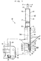
- Fig. 1 shows the most extended state of the hydraulic shock absorber 10.
- the hydraulic shock absorber 10 is constructed in a manner that cylinder 12 comprises a single tube filled with a hydraulic fluid, and a piston 14 is slidably provided therein and is connected to one end of a piston rod 15.
- a gas chamber cartridge 48 which will be described later
- a rod guide 18 Another end of the piston rod 15 penetrates through the rod guide 18 to extend outside the cylinder 12.
- the cylinder 12 is partitioned into a rod side chamber 16B which is filled with a hydraulic fluid and receives and houses the piston rod 15, and a piston-side chamber 16A which is filled with a hydraulic fluid and does not receive and house the piston rod 15.
- the rod guide 18 is provided adjacent to a seal 20, and this rod guide 18 is fixed on the cylinder 12 via the seal 20 in a state of being held between a stopper ring 19 and a retaining member 21.
- the retaining member 21 is supported on the cylinder 12 by means of a bending portion 29 on the other end portion of the cylinder 12.
- one end portion of the piston rod 15 penetrates through the center portion of the piston 14.
- a compression side channel 22 and an extension or expansion side channel (not shown) are alternately formed therethrough at the circumference of the piston rod 15.
- One side face of the piston 14 is provided with a compression side damping valve 24 for closing the compression side channel 22, and the other side face of the piston 14 is provided with an extension side damping valve 25 for closing the extension side channel.
- the piston 14, the compression side damping valve 24 and the extension side damping valve 25 are held down by means of valve retainers 26 and 30 and a nut 27, and are constructed integrally with the piston rod 15.
- the hydraulic fluid in the rod side chamber 16B passes through the extension side channel so as to elastically deform the extension side damping valve 25, and then flows into the piston side chamber 16A. At this time, an extension side damping force is generated by a fluid resistance when the hydraulic fluid elastically deforms the extension side damping valve 25.
- a rebound rubber 28 is fitted into the piston rod 15 in a state of contact with the valve retainer 26.
- the rebound rubber 28 abuts the rod guide 18, the maximum stroke of the hydraulic shock absorber 10 is reached.
- an end member 34 is fastened onto the other end portion of the piston rod 15 by means of a nut 35 and a reinforcing tube 36 is fixed on the outer circumference of the end member 34.
- the reinforcing tube 36 has a cylindrical shape, and is attached with an upper guide bush 37 and a lower guide bush 38 at a predetermined distance at an inner peripheral surface on one side thereof. Further, the reinforcing tube 36 is slidably supported on an outer peripheral surface 12A of the cylinder 12 via the upper guide bush 37 and lower guide bush 38.
- an axle bracket 39 for supporting an axle is fixed to an outer circumferential portion on the other end side of the reinforcing tube 36 by welding.
- the hydraulic shock absorber 10 is an inverted strut type hydraulic shock absorber.
- the hydraulic shock absorber 10 supports the axle via the axle bracket 39 fixed to the reinforcing tube 36, and is supported on the vehicle body via a stud 49 (described later) of the gas chamber cartridge 48. Therefore, the reinforcing tube 36 functions as a strength member for receiving a load between the vehicle side and the axle side, together with the piston rod 15.
- a lower spring bracket 40 is welded to the outer peripheral portion on one side of the reinforcing tube 36.
- An upper spring bracket (not shown) is fixed to the stud 49.
- the suspension spring is stretched between the lower spring bracket 40 and the upper spring bracket.
- a spring load from the suspension spring is supported on the cylinder 12 via the stud 49, and further, is supported on the piston rod 15 via the end member 34.
- a reference numeral 41 denotes a seal member, and the seal member 41 is lubricated by oil filled between the cylinder 12 and the reinforcing tube 36.
- the hydraulic shock absorber 10 is formed with a gas chamber 45 in which a gas such as nitrogen gas is encapsulated, in order to compensate a capacity variation or rate caused when the piston rod 15 enters the cylinder 12 or retreats from the cylinder 12.
- the gas chamber 45 is constructed in the following manner. More specifically, the nitrogen gas is encapsulated in a gas chamber case 46, and a free piston 47, which functions as a partition wall member, is slidably provided in the gas chamber case 46, and thus, a gas chamber cartridge 48, which is a cartridge type, is inserted and fixed to one end side of the cylinder 12.
- the gas chamber 45 and the rod side chamber 16A are partitioned by means of the free piston 47.
- the gas chamber case 46 of the gas chamber cartridge 48 shown in Fig. 3 and Fig. 4 is formed by cold forging. More specifically, a metal mass is placed on a die (not shown) and is extruded by means of punching (not shown) so as to form the gas chamber case. By doing so, a surface roughness on the inner peripheral surface of the case is produced at half of the surface roughness of the slidable range of the piston 14 in the cylinder 12. Further, by cold forging, the gas chamber case 46 is formed integrally with a stud 49 which is used as a fitting portion for attaching the hydraulic shock absorber to the vehicle body.
- the gas chamber cartridge 48 is constructed in the following manner. Nitrogen gas is encapsulated in the gas chamber case 46 thus formed with a predetermined gas pressure, and in this state, the free piston 47 pushed into the gas chamber case 46. Subsequently, an opening end portion of the gas chamber case 46 is bent inwardly so as to form a stopper 50 for preventing the free piston 47 from coming off. There is thus provided a gas chamber cartridge 48 which has a sealed structure encapsulating nitrogen gas, and is of a removable cartridge type.
- the gas chamber cartridge 48 thus constructed is inserted into one end side of the cylinder 12, that is, the end side where the piston rod 15 is not projected, and one end side of the cylinder 12 is bent inwardly, and thus, the gas chamber cartridge 48 is fixed to the cylinder 12 by a bending portion 51.
- an O ring 53 is fitted into a groove 52 formed in the overall outer circumference of the gas chamber case 46, and the gas chamber cartridge 48 and the cylinder 12 are mutually sealed by means of the O ring 53.
- the free piston 47 is prevented from coming off by the stopper 50, and is situated outside the slidable range of the piston 14 in the cylinder 12.
- the gas chamber cartridge 48 is inserted into one end side of the cylinder 12, and one end side of the cylinder 12 is bent inwardly, and thus, the gas chamber cartridge 48 is fixed to the cylinder 12 by the bending portion 51. At this time, the gas chamber cartridge 48 and one end side of the cylinder 12 are sealed by means of the O ring 53.
- the piston 14 connected to the piston rod 15 is inserted into the other end side of the cylinder 12, and the cylinder 12 is filled with a hydraulic fluid, and subsequently, the rod guide 18 and the seal 20 are inserted into the cylinder 12.
- the rod guide 18 and seal 20 are fixed to the cylinder 12 by means of the retaining member 21 supported on the stopper ring 19 and the bending portion 29, and then, the other end side of the cylinder 12 is sealed, and thus, a single-tube separation pressure type hydraulic shock absorber is constructed.
- the hydraulic shock absorber 10 of the aforesaid embodiment has the following effects 1 ⁇ to 4 ⁇ .
- the stopper 50 has been constructed by bending the opening end portion of the gas chamber case 46 of the gas chamber cartridge 48 so that the opening end portion thereof is bent inwardly. As shown by a chain double-dashed line in Fig. 3, a diameter of the inner peripheral surface of the opening end portion of the gas chamber cartridge 48 is reduced so as to form a reduced diameter portion 54. Then, the reduced diameter portion 54 may be used as a stopper for the free piston 47.
- the gas chamber cartridge 48 may be fixed to the cylinder 12 in a manner of forming a male screw on the outer periphery on one end side of the cylinder 12, and screwing a cap onto the male screw.
- the gas chamber cartridge 48 has been provided with the stud 49 for attaching the hydraulic shock absorber 10 to the vehicle body.
- An axle fitting portion having a bearing portion for supporting an axle is formed integrally with the gas chamber case 46 of the gas chamber cartridge 48, and thus, the hydraulic shock absorber 10 may be constructed as an erect strut type hydraulic shock absorber.
- the aforesaid hydraulic shock absorber 10 is a single tube type.
- the hydraulic shock absorber 10 may be a double tube type hydraulic shock absorber which is constructed in a manner that the gas chamber cartridge 48 is inserted into an inner tube, and an outer tube is provided outside the inner tube.
- a hydraulic shock absorber which can reduce the number of machining steps and the number of assembling steps.
Landscapes
- Engineering & Computer Science (AREA)
- General Engineering & Computer Science (AREA)
- Mechanical Engineering (AREA)
- Fluid-Damping Devices (AREA)
- Vehicle Body Suspensions (AREA)
Description
- The present invention relates to a hydraulic shock absorber, which has an improved structure of a gas chamber defined by a partition wall member such as a free piston.
- For hydraulic shock absorbers used in four-wheeled vehicles and two-wheeled vehicles, there has been proposed an erect strut type structure as disclosed in Japanese Utility Model Application Laid-Open (JP-U) No. 51-129988, and an inverted strut type structure shown in Fig. 5. As shown in the prior art, Fig. 5, the
hydraulic shock absorber 1 has a cylinder 2 that is filled with a hydraulic fluid, and apiston 3 is slidably provided therein. Thepiston 3 is provided with a damping valve 4 for generating a damping force, and is connected to one end of apiston rod 5. Further, in order to absorb the capacity resulting from thepiston rod 5 reciprocating in the cylinder 2, the cylinder 2 is formed with agas chamber 6, and afree piston 8 partitioning thegas chamber 6 and anoil chamber 7 is slidably provided in the cylinder 2. - On the inner circumferential surface of the cylinder 2, in the slidable range Y of the
free piston 8 is grease lubrication. In the slidable range X of thepiston 3 is a hydraulic fluid lubrication (oil lubrication). Thus, in order to improve the responsibility offree piston 8 and a resistant abrasion performance of thefree piston 8 and the cylinder 2, a surface roughness (coarseness) of the slidable range Y of thefree piston 8 must be half the degree of the surface roughness of the slidable range X of thepiston 3. For this reason, there is a problem of increasing the number of processes for machining the cylinder 2. - Further, in the cylinder 2, the slidable range Y of the
free piston 8 is set outside the slidable range X of thepiston 3 ; for this reason, a stopper 9 for stopping a sliding motion of thefree piston 8 must be fixed in the cylinder 2. This increases the number of processes for machining the cylinder 2. - Further, a gas is encapsulated in the cylinder 2, and thereafter, a hydraulic fluid is filled therein, and thus, the aforesaid
hydraulic shock absorber 1 is assembled. For this reason, an assembling apparatus becomes complicate, and is made into a large size, and in addition, the number of processes for assembling the hydraulic shock absorber 1 increase further. - Moreover, in the aforesaid hydraulic shock absorber 1, a
stud 2A for vehicle body attachment is fixed onto the cylinder 2 by bending the end portion of the cylinder 2. When a lateral direction (direction perpendicular to an axis of the hydraulic shock absorber) load (torsion (twisting) load F) is applied (acts) onto thestud 2A, an insertion length of thestud 2A with respect to the cylinder 2 is short. For this reason, there is a need of increasing a strength of bending thestud 2A to the end portion of the cylinder 2 in order to secure a strength against the torsion load F. -
DE 38 40 352 discloses a hydraulic shock absorber of the single pipe and gas pressure type comprising a closed cylindrical working cylinder having a first (upper) end and a second (lower) end; a piston rod; a piston connected to the free (upper) end of the piston rod and comprising hydraulic valves; a rod guide screwed to the second end of the cylinder; a substantially cylindrical gas chamber cartridge screwed into the first end of the cylinder, integrally comprising a cap and accommodating and guiding a partition wall member so as to provide a cylinder closure. The hydraulic shock damper further comprises a valve body arranged stationary in the open end of the gas chamber cartridge und comprising throttle valves so as to provide a separation of the other chamber of the gas chamber cartridge from the working space of the cylinder. The valve body allows reducing the gas pressure in said gas-filled one chamber of the gas chamber cartridge from high (typically about 25 bar) to lower gas pressure values (typically 5 to 10 bar). The partition wall member divides the gas chamber cartridge into one chamber comprising a gas sealed under a predetermined pressure and another chamber that is filled with hydraulic fluid and is in communication with the working space of the cylinder that is also filled with hydraulic fluid. The piston is guided by, and slidably disposed in, the cylinder and divides a working space of the cylinder of constant volume filled with hydraulic fluid into a first portion not comprising the piston rod and extending between piston and the valve body, and the a second portion extending between the rod guide and the piston. This hydraulic shock absorber comprises a relatively large number of parts. Manufacturing of this number of individual parts and assembly thereof is relatively costly. - The present invention has been made in view of the aforesaid problems in the prior art. It is, therefore, an object of the present invention to provide a hydraulic shock absorber which can reduce the number of machining, processes and the number of assembling processes.
- As claimed, to achieve the above object, the present invention provides a hydraulic shock absorber which comprises: a cylinder which is filled with a hydraulic fluid; a piston connected to one end of a piston rod and slidably disposed in the cylinder; and a partition wall member which is slidably disposed in the cylinder so as to partition the cylinder into a gas chamber and an oil chamber; wherein a gas chamber cartridge having an opening end portion and which is inserted into one side of the cylinder so as to be fixed thereto, the partition wall member is slidably disposed in a gas chamber case of the gas chamber cartridge, defining one chamber partitioned by the partition wall member of the gas chamber case as the gas chamber encloses a gas therein, and defining the other chamber partitioned by the partition wall member of the gas chamber case as connected to the oil chamber on the other side of the cylinder.
- According to the invention, the gas chamber case comprises a stopper for restricting the partition wall member and the stopper is formed by subjecting the opening end portion to bending.
- Preferably, the gas chamber cartridge is fixed to the cylinder by a bending portion arranged at said one end side of the cylinder.
- More preferably, the bending portion is formed by bending inwardly said one end portion of the cylinder.
- Preferably also, the gas chamber case is formed by cold forging.
- The present invention will be understood more fully from the detailed description of the accompanying drawings of some embodiments of the invention, which are given by way of example only, and are not intended to limit the present invention.
- Fig. 1 is a cross-sectional view showing a hydraulic shock absorber according to one embodiment of the present invention;
- Fig. 2 is an enlarged cross-sectional view showing an axial-direction central portion of the hydraulic shock absorber shown in Fig. 1;
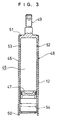
- Fig. 3 is an enlarged cross-sectional view showing an upper portion of the hydraulic shock absorber shown in Fig. 1;
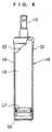
- Fig. 4 is a cross-sectional view showing a gas chamber cartridge of the hydraulic shock absorber shown in Fig. 1; and
- Fig. 5 is a cross-sectional view showing a conventional hydraulic shock absorber.
-
- As shown in Fig. 1, a
hydraulic shock absorber 10, which is used in a four-wheeled vehicle is constructed integrally with a suspension spring (not shown) so as to constitute a cushion unit. This cushion unit is arranged on a vehicle body side and on an axle side. The suspension spring absorbs an impact from a road surface, and the hydraulic shock absorber 10 damps a vibration of the cushion unit, and thus, vibration of the vehicle body is restricted. Fig. 1 shows the most extended state of thehydraulic shock absorber 10. - The
hydraulic shock absorber 10 is constructed in a manner thatcylinder 12 comprises a single tube filled with a hydraulic fluid, and apiston 14 is slidably provided therein and is connected to one end of apiston rod 15. One of the other sides of thecylinder 12 is watertightly closed by agas chamber cartridge 48, which will be described later, and by arod guide 18, respectively. Another end of thepiston rod 15 penetrates through therod guide 18 to extend outside thecylinder 12. By thepiston 14, thecylinder 12 is partitioned into arod side chamber 16B which is filled with a hydraulic fluid and receives and houses thepiston rod 15, and a piston-side chamber 16A which is filled with a hydraulic fluid and does not receive and house thepiston rod 15. - The
rod guide 18 is provided adjacent to aseal 20, and thisrod guide 18 is fixed on thecylinder 12 via theseal 20 in a state of being held between astopper ring 19 and aretaining member 21. The retainingmember 21 is supported on thecylinder 12 by means of abending portion 29 on the other end portion of thecylinder 12. - As shown in Fig. 2, one end portion of the
piston rod 15 penetrates through the center portion of thepiston 14. In thepiston 14, acompression side channel 22 and an extension or expansion side channel (not shown) are alternately formed therethrough at the circumference of thepiston rod 15. One side face of thepiston 14 is provided with a compressionside damping valve 24 for closing thecompression side channel 22, and the other side face of thepiston 14 is provided with an extensionside damping valve 25 for closing the extension side channel. Thepiston 14, the compressionside damping valve 24 and the extensionside damping valve 25 are held down by means ofvalve retainers nut 27, and are constructed integrally with thepiston rod 15. - In a compression stroke of the hydraulic shock absorber 10, the hydraulic fluid in the
piston side chamber 16A passes through thecompression side channel 22 so as to elastically deform the compressionside damping valve 24, and then, flows into therod side chamber 16B. At this time, a compression side damping force is generated by a fluid resistance when the hydraulic fluid elastically deforms the compressionside damping valve 24. - Further, in the extension stroke of the hydraulic shock absorber 10, the hydraulic fluid in the
rod side chamber 16B passes through the extension side channel so as to elastically deform the extensionside damping valve 25, and then flows into thepiston side chamber 16A. At this time, an extension side damping force is generated by a fluid resistance when the hydraulic fluid elastically deforms the extensionside damping valve 25. - In this case, a
rebound rubber 28 is fitted into thepiston rod 15 in a state of contact with thevalve retainer 26. When therebound rubber 28 abuts therod guide 18, the maximum stroke of thehydraulic shock absorber 10 is reached. - In the hydraulic shock absorber 10 shown in Fig. 1, an
end member 34 is fastened onto the other end portion of thepiston rod 15 by means of anut 35 and a reinforcingtube 36 is fixed on the outer circumference of theend member 34. The reinforcingtube 36 has a cylindrical shape, and is attached with anupper guide bush 37 and alower guide bush 38 at a predetermined distance at an inner peripheral surface on one side thereof. Further, thereinforcing tube 36 is slidably supported on an outerperipheral surface 12A of thecylinder 12 via theupper guide bush 37 andlower guide bush 38. - Moreover, an
axle bracket 39 for supporting an axle is fixed to an outer circumferential portion on the other end side of the reinforcingtube 36 by welding. Thehydraulic shock absorber 10 is an inverted strut type hydraulic shock absorber. Thus, the hydraulic shock absorber 10 supports the axle via theaxle bracket 39 fixed to the reinforcingtube 36, and is supported on the vehicle body via a stud 49 (described later) of thegas chamber cartridge 48. Therefore, the reinforcingtube 36 functions as a strength member for receiving a load between the vehicle side and the axle side, together with thepiston rod 15. - A
lower spring bracket 40 is welded to the outer peripheral portion on one side of the reinforcingtube 36. An upper spring bracket (not shown) is fixed to thestud 49. The suspension spring is stretched between thelower spring bracket 40 and the upper spring bracket. A spring load from the suspension spring is supported on thecylinder 12 via thestud 49, and further, is supported on thepiston rod 15 via theend member 34. In Fig. 1 and Fig. 2, areference numeral 41 denotes a seal member, and theseal member 41 is lubricated by oil filled between thecylinder 12 and the reinforcingtube 36. - Now, as shown in Fig. 1 and Fig. 3, the
hydraulic shock absorber 10 is formed with agas chamber 45 in which a gas such as nitrogen gas is encapsulated, in order to compensate a capacity variation or rate caused when thepiston rod 15 enters thecylinder 12 or retreats from thecylinder 12. Further, thegas chamber 45 is constructed in the following manner. More specifically, the nitrogen gas is encapsulated in agas chamber case 46, and afree piston 47, which functions as a partition wall member, is slidably provided in thegas chamber case 46, and thus, agas chamber cartridge 48, which is a cartridge type, is inserted and fixed to one end side of thecylinder 12. Thegas chamber 45 and therod side chamber 16A are partitioned by means of thefree piston 47. - The
gas chamber case 46 of thegas chamber cartridge 48 shown in Fig. 3 and Fig. 4 is formed by cold forging. More specifically, a metal mass is placed on a die (not shown) and is extruded by means of punching (not shown) so as to form the gas chamber case. By doing so, a surface roughness on the inner peripheral surface of the case is produced at half of the surface roughness of the slidable range of thepiston 14 in thecylinder 12. Further, by cold forging, thegas chamber case 46 is formed integrally with astud 49 which is used as a fitting portion for attaching the hydraulic shock absorber to the vehicle body. - The
gas chamber cartridge 48 is constructed in the following manner. Nitrogen gas is encapsulated in thegas chamber case 46 thus formed with a predetermined gas pressure, and in this state, thefree piston 47 pushed into thegas chamber case 46. Subsequently, an opening end portion of thegas chamber case 46 is bent inwardly so as to form astopper 50 for preventing thefree piston 47 from coming off. There is thus provided agas chamber cartridge 48 which has a sealed structure encapsulating nitrogen gas, and is of a removable cartridge type. - The
gas chamber cartridge 48 thus constructed is inserted into one end side of thecylinder 12, that is, the end side where thepiston rod 15 is not projected, and one end side of thecylinder 12 is bent inwardly, and thus, thegas chamber cartridge 48 is fixed to thecylinder 12 by a bendingportion 51. When assembling thegas chamber cartridge 48 into thecylinder 12, anO ring 53 is fitted into agroove 52 formed in the overall outer circumference of thegas chamber case 46, and thegas chamber cartridge 48 and thecylinder 12 are mutually sealed by means of theO ring 53. Also, thefree piston 47 is prevented from coming off by thestopper 50, and is situated outside the slidable range of thepiston 14 in thecylinder 12. - Next, the procedures for assembling the
hydraulic shock absorber 10 will be described. - First, the
gas chamber cartridge 48 is inserted into one end side of thecylinder 12, and one end side of thecylinder 12 is bent inwardly, and thus, thegas chamber cartridge 48 is fixed to thecylinder 12 by the bendingportion 51. At this time, thegas chamber cartridge 48 and one end side of thecylinder 12 are sealed by means of theO ring 53. - Next, the
piston 14 connected to thepiston rod 15 is inserted into the other end side of thecylinder 12, and thecylinder 12 is filled with a hydraulic fluid, and subsequently, therod guide 18 and theseal 20 are inserted into thecylinder 12. Therod guide 18 andseal 20 are fixed to thecylinder 12 by means of the retainingmember 21 supported on thestopper ring 19 and the bendingportion 29, and then, the other end side of thecylinder 12 is sealed, and thus, a single-tube separation pressure type hydraulic shock absorber is constructed. - Thereafter, the reinforcing
tube 36 is inserted into the outer circumference of thecylinder 12, and theend member 34 welded to the reinforcingtube 36 is fixed to thepiston rod 15 bynut 35. Oil is filled between thecylinder 12 and the reinforcingtube 36, that is, betweenguide bushes hydraulic shock absorber 10 is assembled. - Therefore, the
hydraulic shock absorber 10 of the aforesaid embodiment has thefollowing effects 1 ○ to 4 ○. - 1 ○. The
gas chamber 45 defined in thecylinder 12 is constructed by inserting thegas chamber cartridge 48 which is a cartridge type, into thecylinder 12, and is fixed to thecylinder 12 via the bending orcaulking portion 51. The inner cricumferential surface of thegas chamber case 46 of thegas chamber cartridge 48 where the innerfree piston 47 slides, is grease lubricated; on the other hand, the piston slidable range of thecylinder 12 where thepiston 14 slides, is hydraulic fluid lubricated. Thus, the former and latter are lubricated differently from each other, for this reason, in order to improve responsibility and resistant abrasion performance of thefree piston 47, the surface roughness of the gas chamber case must be enhanced more than (about twice as much as) the surface roughness of the piston slidable range of thecylinder 12. However, thegas chamber case 46 is formed by cold forging, so that the surface roughness of the inner circumferential surface can be constructed about half of that of the slidable range of thepiston 14 of thecylinder 12, without being subjected to additional machining. Further, in the inner surface of thecylinder 12, there is no need of enhancing the surface roughness of a portion corresponding to the slidable range of thefree piston 47 more than the surface roughness of the slidable range of thepiston 14. This serves to reduce the number of machining steps for thecylinder 12. - 2 ○ In the case of defining the
gas chamber 45 in thecylinder 12 by directly locating the free piston therein, thecylinder 12 is filled with the nitrogen gas, and thereafter, hydraulic fluid is injected therein; for this reason, an assembling apparatus for the hydraulic shock absorber is big and complicated. However, according to the present embodiment, thegas chamber 45 of thehydraulic shock absorber 10 is constructed with the use of thegas chamber cartridge 48 in which the nitrogen gas has previously been encapsulated by thefree piston 47. Therefore, it is possible to simplify the assembling apparatus for thehydraulic shock absorber 10, and to reduce the number of assembling steps. - 3 ○ In the
gas chamber case 46 of thegas chamber cartridge 48, thestopper 50 for restricting thefree piston 47 is formed by subjecting the opening end portion of thegas chamber case 46 to bending. Thus, even if the hydraulic fluid filled in thecylinder 12 leaks and the oil escapes, thefree piston 47 is restricted by means of thestopper 50 so as not to collide with thepiston 14. Further, thestopper 50 is formed by subjecting the opening end portion of thegas chamber case 46 to bending; therefore, machining can be more simple, and the machining cost can be reduced as compared with the case of constructing the stopper with the use of another member. - 4 ○ The
gas chamber case 46 of thegas chamber cartridge 48 is formed integrally with thestud 49 for attaching thehydraulic shock absorber 10 to the vehicle body. Thus, the strength and reliability of gas leakage prevention can be improved as compared with the case where the gas chamber case and the stud are formed of independent member and are connected to each other. In particular, in the case of the invert strut typehydraulic shock absorber 10 having thestud 49 attached to the vehicle body, even if a torsion load F of the direction perpendicular to the axis of thehydraulic shock absorber 10 is applied to thestud 49, a portion where thegas chamber case 46 is inserted into thecylinder 12 is long, so that the strength against the torsion load F can be enhanced depending upon the inserted length of thegas chamber case 46 without enhancing the bending strength of thecylinder 12 for fixing thegas chamber case 46 of thegas chamber cartridge 48. -
- Also, in the aforesaid embodiment, the
stopper 50 has been constructed by bending the opening end portion of thegas chamber case 46 of thegas chamber cartridge 48 so that the opening end portion thereof is bent inwardly. As shown by a chain double-dashed line in Fig. 3, a diameter of the inner peripheral surface of the opening end portion of thegas chamber cartridge 48 is reduced so as to form a reduceddiameter portion 54. Then, the reduceddiameter portion 54 may be used as a stopper for thefree piston 47. - Further, in place of the bending
portion 51 for fixing thegas chamber cartridge 48 to one end portion of thecylinder 12, thegas chamber cartridge 48 may be fixed to thecylinder 12 in a manner of forming a male screw on the outer periphery on one end side of thecylinder 12, and screwing a cap onto the male screw. - Furthermore, the
gas chamber cartridge 48 has been provided with thestud 49 for attaching thehydraulic shock absorber 10 to the vehicle body. An axle fitting portion having a bearing portion for supporting an axle is formed integrally with thegas chamber case 46 of thegas chamber cartridge 48, and thus, thehydraulic shock absorber 10 may be constructed as an erect strut type hydraulic shock absorber. - In addition, the aforesaid
hydraulic shock absorber 10 is a single tube type. Thehydraulic shock absorber 10 may be a double tube type hydraulic shock absorber which is constructed in a manner that thegas chamber cartridge 48 is inserted into an inner tube, and an outer tube is provided outside the inner tube. - As is evident from the above description, according to the present invention, there can be provided a hydraulic shock absorber which can reduce the number of machining steps and the number of assembling steps.
- Although the invendon has been illustrated and described with respect to several exemplary embodiments thereof, it should be understood by those skilled in the art that the foregoing and various other changes, omissions and additions may be made to the present invention without departing from the scope as defined by the appended claims. Therefore, the present invention should not be understood as limited to the specific embodiment set out above but to include all possible embodiments which can be embodied within a scope encompassed and equivalents thereof with respect to the feature set out in the appended claims.
Claims (6)
- A hydraulic shock absorber (10), comprising:a cylinder (12) which is filled with a hydraulic fluid;a piston (14) connected to one end of a piston rod (15), and which is slidably disposed in the cylinder (12); anda partition wall member (47) which is slidably disposed in the cylinder (12) so as to partition the cylinder (12) into a gas chamber (45) and an oil chamber (16A, 16B), anda gas chamber cartridge (48) having an opening end portion and which is inserted into one side of the cylinder (12) so as to be fixed thereto, said partition wall member (47) being slidably disposed in a gas chamber case (46) of the gas chamber cartridge (48), and defining one chamber partitioned by the partition wall member (47) of the gas chamber case (46) as the gas chamber (45) encloses a gas therein, and defining on other chamber partitioned by the partition wall member (47) of the gase chamber case connected to the oil chamber (16A, 16B) on the other side of the cylinder; characterized in that the gas chamber case (46) comprises a stopper (50) for restricting the partition wall member (47), the stopper (50) being formed by subjecting the opening end portion to bending.
- The hydraulic shock absorber according to claim 1, wherein the gas chamber cartridge (48) is fixed to the cylinder (12) by a bending portion (51) arranged at said one end side of the cylinder (12).
- The hydraulic shock absorber according to claim 1 or 2, wherein the bending portion (51) is formed by bending inwardly said one end portion of the cylinder (12).
- The hydraulic shock absorber according to anyone of the claim 1 to 3, wherein the gas chamber case (46) is formed by cold forging.
- The hydraulic shock absorber according to anyone of the preceding claims, wherein the gas chamber case (46) is formed integrally with a fitting portion (49, 59) for a attaching the hydraulic shock absorber (10) to a vehicle body or an axle.
- The hydraulic shook absorber according to claim 5, wherein the hydraulic shock absorber (10) is of an invert strut type and the fitting portion (41, 51) is formed integrally with the gas chamber case (46) attached to a vehicle body side, and the piston rod (15) is attached to an axle side.
Applications Claiming Priority (3)
| Application Number | Priority Date | Filing Date | Title |
|---|---|---|---|
| JP9259408A JPH1182590A (en) | 1997-09-09 | 1997-09-09 | Hydraulic shock absorber |
| JP25940897 | 1997-09-09 | ||
| JP259408/97 | 1997-09-09 |
Publications (3)
| Publication Number | Publication Date |
|---|---|
| EP0902211A2 EP0902211A2 (en) | 1999-03-17 |
| EP0902211A3 EP0902211A3 (en) | 2001-07-11 |
| EP0902211B1 true EP0902211B1 (en) | 2005-06-29 |
Family
ID=17333709
Family Applications (1)
| Application Number | Title | Priority Date | Filing Date |
|---|---|---|---|
| EP98113231A Expired - Lifetime EP0902211B1 (en) | 1997-09-09 | 1998-07-16 | Hydraulic shock absorber |
Country Status (4)
| Country | Link |
|---|---|
| US (1) | US6182806B1 (en) |
| EP (1) | EP0902211B1 (en) |
| JP (1) | JPH1182590A (en) |
| DE (1) | DE69830692T2 (en) |
Families Citing this family (12)
| Publication number | Priority date | Publication date | Assignee | Title |
|---|---|---|---|---|
| JP4100657B2 (en) * | 2000-07-05 | 2008-06-11 | カヤバ工業株式会社 | Shock absorber seal structure with vehicle height adjustment function |
| US6892865B2 (en) * | 2003-08-01 | 2005-05-17 | Arvin Technologies, Inc. | Monotube shock absorber remote reservoir fluid connection |
| US20050051397A1 (en) * | 2003-09-04 | 2005-03-10 | Brian Goscinski | Remote adjustable shock absorber |
| GB2418001A (en) * | 2004-09-09 | 2006-03-15 | Tenneco Automotive Operating | A piston and cylinder strut assembly in which an end of the piston rod defines a contoured surface |
| JP2008087592A (en) * | 2006-09-29 | 2008-04-17 | Yokohama Rubber Co Ltd:The | Vehicle body supporting system |
| KR101089574B1 (en) * | 2009-08-18 | 2011-12-05 | 황의배 | Car Shock Absorber |
| JP5865514B2 (en) * | 2012-10-08 | 2016-02-17 | ベイジンウェスト・インダストリーズ・カンパニー・リミテッドBeijingwest Industries Co., Ltd. | Fluid damper assembly having a gas cup lubrication chamber |
| KR101479515B1 (en) * | 2013-06-25 | 2015-01-07 | 주식회사 한국가스스프링 | A gas cylinder for shut off the grease |
| US9108484B2 (en) * | 2013-07-25 | 2015-08-18 | Tenneco Automotive Operating Company Inc. | Recuperating passive and active suspension |
| US10434835B2 (en) | 2016-02-24 | 2019-10-08 | Tenneco Automotive Operating Company Inc. | Monotube active suspension system having different system layouts for controlling pump flow distribution |
| DE102016014779A1 (en) | 2016-12-10 | 2018-06-14 | Hydac Technology Gmbh | Hydropneumatic piston-cylinder arrangement |
| CN112211942B (en) | 2019-11-04 | 2021-12-17 | 北京京西重工有限公司 | Bracket, hydraulic damper assembly and connection method between bracket and hydraulic damper assembly |
Family Cites Families (12)
| Publication number | Priority date | Publication date | Assignee | Title |
|---|---|---|---|---|
| DE2111967C3 (en) * | 1971-03-12 | 1974-11-28 | Peddinghaus Carl Ullrich Dr | Hydropneumatic vibration damper |
| US3955655A (en) * | 1972-03-17 | 1976-05-11 | Rene Pornin | Adjustable liquid-operated shock-absorber |
| DE2223968A1 (en) * | 1972-05-17 | 1973-12-06 | Carl Ullrich Dr Peddinghaus | HYDROPNEUMATIC VIBRATION DAMPER |
| JPS5434152Y2 (en) | 1975-03-24 | 1979-10-19 | ||
| JPS51129988A (en) | 1975-05-06 | 1976-11-11 | Om Seisakusho:Kk | Lathe for machining crank shaft |
| GB2149055B (en) * | 1983-09-26 | 1987-11-04 | Nhk Spring Co Ltd | Vehicle suspension unit with damping & spring rate adjustable |
| FR2608242B1 (en) * | 1986-12-12 | 1989-03-31 | Aerospatiale | SHOCK ABSORBER, CYLINDER PLUG COMPRISING SAME, AND LANDING GEAR EQUIPPED WITH SUCH A PLUG |
| DE3840352A1 (en) * | 1988-11-30 | 1990-06-21 | Irmscher Gmbh | Single-tube gas-pressure shock absorber |
| JPH03271014A (en) * | 1990-03-20 | 1991-12-03 | Tokico Ltd | suspension equipment |
| DE4403127C2 (en) * | 1993-08-04 | 1998-01-22 | Mannesmann Sachs Ag | Impact absorber with deformation body |
| JPH08210412A (en) * | 1995-02-06 | 1996-08-20 | Showa:Kk | Inverted strut damper |
| US5797594A (en) * | 1995-07-22 | 1998-08-25 | Tokico, Ltd. | Hydraulic shock absorber |
-
1997
- 1997-09-09 JP JP9259408A patent/JPH1182590A/en active Pending
-
1998
- 1998-07-16 DE DE69830692T patent/DE69830692T2/en not_active Expired - Fee Related
- 1998-07-16 EP EP98113231A patent/EP0902211B1/en not_active Expired - Lifetime
- 1998-08-12 US US09/132,832 patent/US6182806B1/en not_active Expired - Fee Related
Also Published As
| Publication number | Publication date |
|---|---|
| US6182806B1 (en) | 2001-02-06 |
| JPH1182590A (en) | 1999-03-26 |
| DE69830692T2 (en) | 2006-05-04 |
| EP0902211A3 (en) | 2001-07-11 |
| EP0902211A2 (en) | 1999-03-17 |
| DE69830692D1 (en) | 2005-08-04 |
Similar Documents
| Publication | Publication Date | Title |
|---|---|---|
| US11187298B2 (en) | Extension assembly for damper | |
| EP0902211B1 (en) | Hydraulic shock absorber | |
| US5518225A (en) | Pneumatic spring-vibration damper assembly | |
| EP0974476B1 (en) | Spring seat fixing structure for a hydraulic shock absorber | |
| US6913127B2 (en) | Adjacent baffle design for shock absorber | |
| EP0660008A2 (en) | Shock absorber with hydraulic rebound stop | |
| US20070051574A1 (en) | Rod guide seal | |
| CN111108302B (en) | Front fork and method for manufacturing front fork | |
| US5501438A (en) | Motor vehicle vibration damper | |
| JPS5912438Y2 (en) | hydraulic shock absorber | |
| US7252031B2 (en) | Cylinder apparatus | |
| US4966257A (en) | Shock absorbing or oscillation damper device | |
| JP2001180245A (en) | Vehicle suspension | |
| JPH10238582A (en) | Hydraulic shock absorber and method for filling hydraulic oil into hydraulic shock absorber | |
| US4331224A (en) | Hydraulic shock absorber for vehicles | |
| US20060042895A1 (en) | Base cup connection for shock absorber | |
| JP2000304082A (en) | Hydraulic shock absorber | |
| JP2005076713A (en) | Single cylinder hydraulic shock absorber support member mounting structure | |
| US7240776B2 (en) | Bottom valve apparatus of hydraulic shock absorber | |
| JP7113143B2 (en) | Cylinder device | |
| US6357734B1 (en) | Suspension damper with vehicle spring preload | |
| CN219472631U (en) | Cap member for automobile damper and automobile damper | |
| CN220248787U (en) | Cap member for automobile damper and automobile damper | |
| CN220248798U (en) | Cap member for automobile damper and automobile damper | |
| US12558934B2 (en) | Damper oil seal cap with seal protection feature |
Legal Events
| Date | Code | Title | Description |
|---|---|---|---|
| PUAI | Public reference made under article 153(3) epc to a published international application that has entered the european phase |
Free format text: ORIGINAL CODE: 0009012 |
|
| AK | Designated contracting states |
Kind code of ref document: A2 Designated state(s): DE GB |
|
| AX | Request for extension of the european patent |
Free format text: AL;LT;LV;MK;RO;SI |
|
| PUAL | Search report despatched |
Free format text: ORIGINAL CODE: 0009013 |
|
| AK | Designated contracting states |
Kind code of ref document: A3 Designated state(s): AT BE CH CY DE DK ES FI FR GB GR IE IT LI LU MC NL PT SE |
|
| AX | Request for extension of the european patent |
Free format text: AL;LT;LV;MK;RO;SI |
|
| 17P | Request for examination filed |
Effective date: 20020110 |
|
| AKX | Designation fees paid |
Free format text: DE GB |
|
| 17Q | First examination report despatched |
Effective date: 20031107 |
|
| GRAP | Despatch of communication of intention to grant a patent |
Free format text: ORIGINAL CODE: EPIDOSNIGR1 |
|
| GRAS | Grant fee paid |
Free format text: ORIGINAL CODE: EPIDOSNIGR3 |
|
| GRAA | (expected) grant |
Free format text: ORIGINAL CODE: 0009210 |
|
| AK | Designated contracting states |
Kind code of ref document: B1 Designated state(s): DE GB |
|
| REG | Reference to a national code |
Ref country code: GB Ref legal event code: FG4D |
|
| REF | Corresponds to: |
Ref document number: 69830692 Country of ref document: DE Date of ref document: 20050804 Kind code of ref document: P |
|
| PLBE | No opposition filed within time limit |
Free format text: ORIGINAL CODE: 0009261 |
|
| STAA | Information on the status of an ep patent application or granted ep patent |
Free format text: STATUS: NO OPPOSITION FILED WITHIN TIME LIMIT |
|
| 26N | No opposition filed |
Effective date: 20060330 |
|
| PGFP | Annual fee paid to national office [announced via postgrant information from national office to epo] |
Ref country code: DE Payment date: 20070711 Year of fee payment: 10 |
|
| PGFP | Annual fee paid to national office [announced via postgrant information from national office to epo] |
Ref country code: GB Payment date: 20070710 Year of fee payment: 10 |
|
| GBPC | Gb: european patent ceased through non-payment of renewal fee |
Effective date: 20080716 |
|
| PG25 | Lapsed in a contracting state [announced via postgrant information from national office to epo] |
Ref country code: DE Free format text: LAPSE BECAUSE OF NON-PAYMENT OF DUE FEES Effective date: 20090203 |
|
| PG25 | Lapsed in a contracting state [announced via postgrant information from national office to epo] |
Ref country code: GB Free format text: LAPSE BECAUSE OF NON-PAYMENT OF DUE FEES Effective date: 20080716 |