EP0901843A2 - Easy insert tube cleaner - Google Patents
Easy insert tube cleaner Download PDFInfo
- Publication number
- EP0901843A2 EP0901843A2 EP98116231A EP98116231A EP0901843A2 EP 0901843 A2 EP0901843 A2 EP 0901843A2 EP 98116231 A EP98116231 A EP 98116231A EP 98116231 A EP98116231 A EP 98116231A EP 0901843 A2 EP0901843 A2 EP 0901843A2
- Authority
- EP
- European Patent Office
- Prior art keywords
- scraping
- tube
- shaft
- tube cleaner
- tongue
- Prior art date
- Legal status (The legal status is an assumption and is not a legal conclusion. Google has not performed a legal analysis and makes no representation as to the accuracy of the status listed.)
- Granted
Links
Images

Classifications
-
- B—PERFORMING OPERATIONS; TRANSPORTING
- B08—CLEANING
- B08B—CLEANING IN GENERAL; PREVENTION OF FOULING IN GENERAL
- B08B9/00—Cleaning hollow articles by methods or apparatus specially adapted thereto
- B08B9/02—Cleaning pipes or tubes or systems of pipes or tubes
- B08B9/027—Cleaning the internal surfaces; Removal of blockages
- B08B9/04—Cleaning the internal surfaces; Removal of blockages using cleaning devices introduced into and moved along the pipes
- B08B9/053—Cleaning the internal surfaces; Removal of blockages using cleaning devices introduced into and moved along the pipes moved along the pipes by a fluid, e.g. by fluid pressure or by suction
- B08B9/055—Cleaning the internal surfaces; Removal of blockages using cleaning devices introduced into and moved along the pipes moved along the pipes by a fluid, e.g. by fluid pressure or by suction the cleaning devices conforming to, or being conformable to, substantially the same cross-section of the pipes, e.g. pigs or moles
- B08B9/0553—Cylindrically shaped pigs
-
- B—PERFORMING OPERATIONS; TRANSPORTING
- B08—CLEANING
- B08B—CLEANING IN GENERAL; PREVENTION OF FOULING IN GENERAL
- B08B9/00—Cleaning hollow articles by methods or apparatus specially adapted thereto
- B08B9/02—Cleaning pipes or tubes or systems of pipes or tubes
- B08B9/027—Cleaning the internal surfaces; Removal of blockages
- B08B9/04—Cleaning the internal surfaces; Removal of blockages using cleaning devices introduced into and moved along the pipes
- B08B9/053—Cleaning the internal surfaces; Removal of blockages using cleaning devices introduced into and moved along the pipes moved along the pipes by a fluid, e.g. by fluid pressure or by suction
- B08B9/055—Cleaning the internal surfaces; Removal of blockages using cleaning devices introduced into and moved along the pipes moved along the pipes by a fluid, e.g. by fluid pressure or by suction the cleaning devices conforming to, or being conformable to, substantially the same cross-section of the pipes, e.g. pigs or moles
- B08B9/0557—Pigs with rings shaped cleaning members, e.g. cup shaped pigs
-
- F—MECHANICAL ENGINEERING; LIGHTING; HEATING; WEAPONS; BLASTING
- F28—HEAT EXCHANGE IN GENERAL
- F28G—CLEANING OF INTERNAL OR EXTERNAL SURFACES OF HEAT-EXCHANGE OR HEAT-TRANSFER CONDUITS, e.g. WATER TUBES OR BOILERS
- F28G1/00—Non-rotary, e.g. reciprocated, appliances
- F28G1/12—Fluid-propelled scrapers, bullets, or like solid bodies
Definitions
- the present invention is to a tube cleaning device for use in cleaning the inner wall of a tube or conduit, and more specifically to a tube cleaner that is insertable into an open end of a tube, such as a condenser tube, and forced through the tube by a fluid, such as water, discharged from pressurized fluid gun to remove deposits on the inner wall surface of the tube.
- a tube cleaner that is insertable into an open end of a tube, such as a condenser tube, and forced through the tube by a fluid, such as water, discharged from pressurized fluid gun to remove deposits on the inner wall surface of the tube.
- a resilient scraping tool is inserted into an open end of the tube and a pressurized fluid is charged to the open end of the tube to propel the scraping tool through the tube.
- the scraping tool scrapes deposits from the inner wall of the tube and discharges the deposits from the other end of the tube.
- Such tube cleaners have been used extensively and examples of typical such tube cleaners are shown, for example, in U.S. 2,170,997; U.S. 2,418,509; U.S. 2,734,208, and U.S. 4,281,432.
- These tube cleaners use scraping elements that are spaced along a shaft, with scraping blades of adjacent scraping elements offset from each other so that the deposits on the inner tube wall are scraped away along the entire 360° inner circumference thereof.
- the scraper elements, with the scraper blades are usually formed from steel and are flexible enough to be inserted into the open end of a tube while making contact with and removing deposits from the tube wall upon passage through the tube.
- the easy insert tube cleaner of the present invention has a shaft with a nose portion at the front end, a tail portion at the rear end, and a plurality of spaced scraper devices between the nose portion and tail portion.
- the scraper device is a U-shaped scraper having a base and at least two leg portions, with each leg portion extending in the direction of the tail portion of the tube cleaner.
- Scraping sections are provided on the terminal ends of the leg portions of the scraper device which extend radially outwardly from the shaft of the tube cleaner.
- a tongue is provided on the leg portion of the scraper device which extends from the leg portion rearwardly and outwardly to a position adjacent a scraping edge of the scraping section of the scraper device.
- the tongue is preferably a section partially cut from the leg portion of the scraper device and bent outwardly so as to be outwardly and rearwardly extending.
- the tube cleaner of the present invention is constructed so as to enable easy insertion into an open end of a tube, such as a condenser tube, that is to be cleaned.
- the tube cleaner is made of a metal such as carbon steel or stainless steel which provides sufficient strength and resiliency to scrape deposits from the inner wall of a tube through which the tube cleaner is passed.
- an easy insert tube cleaner 1 that has shaft 2 with a nose portion 3 at the front end and a tail portion 4 at the rear end thereof.
- the nose portion 3 may have a rivet head which secures scraper devices on the shaft 2, while the tail portion 4 is adapted to provide a surface for impingement of pressurized fluid thereon to drive the tube cleaner through a tube, as known in the art.
- a plurality of scraper devices 5, shown as four scraper devices, 5a, 5b, 5c and 5d in Figure 1, are spaced along the shaft 2 between the nose portion 3 and tail portion 4.
- the scraper devices 5 are U-shaped and have a base 6 and at least two leg portions 7 which extend in the direction of the tail portion 4 of the easy insert tube cleaner 1 and have a scraping section 8 at the terminal end 9 of the leg portion 7 which scraping section 8 has a scraping edge 10.
- the scraper devices 5 are positioned along the shaft of the easy insert tube cleaner 1 in a manner such that the leg portions 7 and scraping edges 10 of adjacent scraper devices 5 are offset from each other. Such positioning is known in the art so as to provide scraping completely around the circumference of a pipe internal surface.
- a tongue 11 is provided on the leg portion 7 of the scraper device 5, which tongue extends from the leg portion rearwardly and outwardly to a position adjacent the scraping edge 10 of the scraping section 8 of the scraper device 5.
- the tongue 11 extends outwardly from the leg portion 7 and has an outer edge 12, which is spaced a distance d from the shaft 2 which is substantially equal to, but less than the distance d 1 which is the distance of the scraping edge 10 or the scraping section 8 from the shaft 2 of the easy insert tube cleaner 1.
- the outer edge of the tongue 11 is a distance d which is about 0.010 inch less than the distance d 1.
- the tongue 11 is readily formed by stamping the same out of the metal substrate that forms the leg portion 7 of the scraper device 5.
Abstract
Description
- The present invention is to a tube cleaning device for use in cleaning the inner wall of a tube or conduit, and more specifically to a tube cleaner that is insertable into an open end of a tube, such as a condenser tube, and forced through the tube by a fluid, such as water, discharged from pressurized fluid gun to remove deposits on the inner wall surface of the tube.
- In the cleaning of the inner wall of tube, such as condenser tubes, in power plants, to improve the efficiency of heat transfer therethrough, a resilient scraping tool is inserted into an open end of the tube and a pressurized fluid is charged to the open end of the tube to propel the scraping tool through the tube. During passage through the tube, the scraping tool scrapes deposits from the inner wall of the tube and discharges the deposits from the other end of the tube. Such tube cleaners have been used extensively and examples of typical such tube cleaners are shown, for example, in U.S. 2,170,997; U.S. 2,418,509; U.S. 2,734,208, and U.S. 4,281,432. These tube cleaners use scraping elements that are spaced along a shaft, with scraping blades of adjacent scraping elements offset from each other so that the deposits on the inner tube wall are scraped away along the entire 360° inner circumference thereof. The scraper elements, with the scraper blades, are usually formed from steel and are flexible enough to be inserted into the open end of a tube while making contact with and removing deposits from the tube wall upon passage through the tube.
- It is an object of the present invention to provide a tube cleaner which is more easily inserted into an open end of a tube to be cleaned.
- The easy insert tube cleaner of the present invention has a shaft with a nose portion at the front end, a tail portion at the rear end, and a plurality of spaced scraper devices between the nose portion and tail portion. The scraper device is a U-shaped scraper having a base and at least two leg portions, with each leg portion extending in the direction of the tail portion of the tube cleaner. Scraping sections are provided on the terminal ends of the leg portions of the scraper device which extend radially outwardly from the shaft of the tube cleaner. A tongue is provided on the leg portion of the scraper device which extends from the leg portion rearwardly and outwardly to a position adjacent a scraping edge of the scraping section of the scraper device. The tongue is preferably a section partially cut from the leg portion of the scraper device and bent outwardly so as to be outwardly and rearwardly extending.
- The easy insert tube cleaner of the present invention will be more readily understood by reference to the following description and the accompanying drawings, wherein:
- Figure 1 is a side elevational view of an embodiment of an easy insert tube cleaner of the present invention;
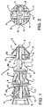
- Figure 2 is a front view of the easy insert tube cleaner of Figure 1;
- Figure 3 is a cross-sectional view through one of the scraper devices used on the easy insert tube cleaner shown in Figure 1; and
- Figure 4 is a view showing insertion of the easy insert tube cleaner of the present invention into the open end of a tube to be cleaned.
-
- The tube cleaner of the present invention is constructed so as to enable easy insertion into an open end of a tube, such as a condenser tube, that is to be cleaned. The tube cleaner is made of a metal such as carbon steel or stainless steel which provides sufficient strength and resiliency to scrape deposits from the inner wall of a tube through which the tube cleaner is passed.
- Referring now to the drawings, an easy insert tube cleaner 1 is shown that has
shaft 2 with anose portion 3 at the front end and a tail portion 4 at the rear end thereof. Thenose portion 3 may have a rivet head which secures scraper devices on theshaft 2, while the tail portion 4 is adapted to provide a surface for impingement of pressurized fluid thereon to drive the tube cleaner through a tube, as known in the art. A plurality ofscraper devices 5, shown as four scraper devices, 5a, 5b, 5c and 5d in Figure 1, are spaced along theshaft 2 between thenose portion 3 and tail portion 4. Thescraper devices 5 are U-shaped and have abase 6 and at least twoleg portions 7 which extend in the direction of the tail portion 4 of the easy insert tube cleaner 1 and have ascraping section 8 at theterminal end 9 of theleg portion 7 whichscraping section 8 has ascraping edge 10. Thescraper devices 5 are positioned along the shaft of the easy insert tube cleaner 1 in a manner such that theleg portions 7 andscraping edges 10 ofadjacent scraper devices 5 are offset from each other. Such positioning is known in the art so as to provide scraping completely around the circumference of a pipe internal surface. - In the present easy insert tube cleaner 1, a
tongue 11 is provided on theleg portion 7 of thescraper device 5, which tongue extends from the leg portion rearwardly and outwardly to a position adjacent thescraping edge 10 of thescraping section 8 of thescraper device 5. As shown in the drawings, thetongue 11 extends outwardly from theleg portion 7 and has anouter edge 12, which is spaced a distance d from theshaft 2 which is substantially equal to, but less than the distance d1 which is the distance of thescraping edge 10 or thescraping section 8 from theshaft 2 of the easy insert tube cleaner 1. Preferably, the outer edge of thetongue 11 is a distance d which is about 0.010 inch less than the distance d1. - The
tongue 11 is readily formed by stamping the same out of the metal substrate that forms theleg portion 7 of thescraper device 5. - The provision of the
tongue 11 on theleg portion 7 of thescraper device 5, causes theleg portions 7 to bend inwardly upon insertion into atube 12, as indicated by the arrows in Figure 4, and thus forces theleg portions 7 to move together and provides for a less severe contact with thescraping section 8 of the tube cleaner 1 with the end wall of the tube. By thus moving theleg portions 7 together, easier insertion of the tube cleaner 1 into an open end of a tube is effected.
Claims (9)
- A tube cleaner comprising a shaft having a nose portion at a front end and tail portion at a rear end thereof; and a plurality of spaced scraper devices secured to the shaft intermediate the nose portion and tail portion, said scraper device comprising a U-shaped scraper having a base and at least two leg portions, said leg portions extending in the direction of said tail portion and having scraping sections extending outwardly from a terminal end thereof; and a tongue on said leg portion extending from said leg portion rearwardly and outwardly to a position adjacent said scraping section.
- The tube cleaner as defined in Claim 1 wherein the scraping section of said scraper device has a scraping edge and said tongue has an outer edge, with said outer edge spaced a distance from said shaft which is substantially equal to but less than the distance of said scraping edge from said shaft.
- The tube cleaner as defined in Claim 1 wherein said scraper device is formed from steel and said tongue is punched out of said leg portion.
- The tube cleaner as defined in Claim 1 wherein said scraper device is formed of carbon steel.
- The tube cleaner as defined in Claim 1 wherein said scraper device is formed of stainless steel.
- The tube cleaner as defined in Claim 4 wherein said tongue has an outer edge which is spaced a distance from said shaft which is substantially equal to but less than a distance of a scraping edge of the scraping section from said shaft.
- The tube cleaner as defined in Claim 6 wherein the outer edge of said tongue is spaced about 0.010 inch from the scraping edge of said scraping section.
- The tube cleaner as defined in Claim 1 wherein said tongue is formed by punching the same from the leg portion.
- A tube cleaner comprising a shaft having a nose portion at a front end and tail portion at a rear end thereof; and a plurality of spaced scraper devices secured to the shaft intermediate the nose portion and tail portion, said scraper device comprising a U-shaped scraper having a base and at least two leg portions, said leg portions extending in the direction of said tail portion and having scraping sections extending outwardly from a terminal end thereof and having a scraping edge; and a tongue on said leg portion extending from said leg portion rearwardly and outwardly to a position adjacent said scraping section, said tongue having an outer edge which is spaced a distance from said shaft which is substantially equal to but less than the scraping edge of said scraping section.
Applications Claiming Priority (2)
| Application Number | Priority Date | Filing Date | Title |
|---|---|---|---|
| US928847 | 1997-09-12 | ||
| US08/928,847 US5784745A (en) | 1997-09-12 | 1997-09-12 | Easy insert tube cleaner |
Publications (3)
| Publication Number | Publication Date |
|---|---|
| EP0901843A2 true EP0901843A2 (en) | 1999-03-17 |
| EP0901843A3 EP0901843A3 (en) | 1999-12-22 |
| EP0901843B1 EP0901843B1 (en) | 2003-03-26 |
Family
ID=25456867
Family Applications (1)
| Application Number | Title | Priority Date | Filing Date |
|---|---|---|---|
| EP98116231A Expired - Lifetime EP0901843B1 (en) | 1997-09-12 | 1998-08-27 | Easy insert tube cleaner |
Country Status (8)
| Country | Link |
|---|---|
| US (1) | US5784745A (en) |
| EP (1) | EP0901843B1 (en) |
| AU (1) | AU705973B2 (en) |
| CA (1) | CA2246810C (en) |
| DE (1) | DE69812512T2 (en) |
| ES (1) | ES2195245T3 (en) |
| MX (1) | MXPA98007396A (en) |
| PT (1) | PT901843E (en) |
Families Citing this family (13)
| Publication number | Priority date | Publication date | Assignee | Title |
|---|---|---|---|---|
| KR200161158Y1 (en) * | 1996-07-23 | 1999-11-15 | 이종철 | Apparatus for eliminating pollutant from inside of pipe |
| US5983994A (en) * | 1997-10-30 | 1999-11-16 | Electric Power Research Institute, Inc. | Method and apparatus for on-line cleaning of and improvement of heat transfer in a heat exchanger tube |
| US6085376A (en) * | 1998-08-07 | 2000-07-11 | Itc, Inc. | Pipe cleaning apparatus |
| US20040035445A1 (en) * | 2002-08-23 | 2004-02-26 | Saxon Edward G. | Automated tube cleaner |
| US7601282B2 (en) * | 2005-10-24 | 2009-10-13 | Johns Manville | Processes for forming a fiber-reinforced product |
| CN101506611B (en) * | 2006-12-31 | 2011-05-11 | 北京化工大学 | A self-cleaning enhanced heat transfer device inside a tube |
| DE102010010280A1 (en) | 2010-03-07 | 2011-09-08 | Karl-Heinz Grüter | Device for internal cleaning of heat exchanger pipes, has nozzle, which is positioned in heat exchanger tubes, from which scratches are loaded with pressurized water |
| DE202010017794U1 (en) | 2010-02-12 | 2012-09-14 | Karl-Heinz Grüter | Device for cleaning the inside of pipes |
| DE102010010281A1 (en) | 2010-03-07 | 2011-09-08 | Karl-Heinz Grüter | Device for internal cleaning of heat exchanger pipes, has nozzle, which is positioned in heat exchanger tubes, from which scratches are loaded with pressurized water |
| EP2534437A2 (en) | 2010-02-12 | 2012-12-19 | Jarin GmbH | Device for internally cleaning pipes |
| USD770114S1 (en) * | 2014-08-29 | 2016-10-25 | Ningbo Rotchi Business Co., Ltd. | Brush for cleaning pipes |
| US9375765B1 (en) | 2015-10-09 | 2016-06-28 | Crossford International, Llc | Tube scraper projectile |
| WO2020076873A1 (en) * | 2018-10-08 | 2020-04-16 | Crossford International, Llc | Systems and methods for belt-fed tube cleaning |
Citations (3)
| Publication number | Priority date | Publication date | Assignee | Title |
|---|---|---|---|---|
| US2170997A (en) * | 1936-05-23 | 1939-08-29 | Cecil M Griffin | Tube cleaner |
| US2317542A (en) * | 1941-08-11 | 1943-04-27 | Bernard V Brunt | Device for cleaning tubes |
| EP0698423A1 (en) * | 1994-08-08 | 1996-02-28 | Conco Systems Inc. | Tube cleaner for removing hard deposits |
Family Cites Families (3)
| Publication number | Priority date | Publication date | Assignee | Title |
|---|---|---|---|---|
| US2734208A (en) * | 1956-02-14 | Tube cleaner | ||
| US2418509A (en) * | 1944-11-28 | 1947-04-08 | Cecil M Griffin | Fluid propelled articulated scraper for cleaning tubes |
| US4281432A (en) * | 1979-08-02 | 1981-08-04 | Condenser Cleaners Mfg. Co., Inc. | Tube cleaner |
-
1997
- 1997-09-12 US US08/928,847 patent/US5784745A/en not_active Expired - Lifetime
-
1998
- 1998-08-27 ES ES98116231T patent/ES2195245T3/en not_active Expired - Lifetime
- 1998-08-27 DE DE69812512T patent/DE69812512T2/en not_active Expired - Lifetime
- 1998-08-27 PT PT98116231T patent/PT901843E/en unknown
- 1998-08-27 EP EP98116231A patent/EP0901843B1/en not_active Expired - Lifetime
- 1998-09-08 CA CA002246810A patent/CA2246810C/en not_active Expired - Lifetime
- 1998-09-11 AU AU84208/98A patent/AU705973B2/en not_active Ceased
- 1998-09-11 MX MXPA98007396A patent/MXPA98007396A/en active IP Right Grant
Patent Citations (3)
| Publication number | Priority date | Publication date | Assignee | Title |
|---|---|---|---|---|
| US2170997A (en) * | 1936-05-23 | 1939-08-29 | Cecil M Griffin | Tube cleaner |
| US2317542A (en) * | 1941-08-11 | 1943-04-27 | Bernard V Brunt | Device for cleaning tubes |
| EP0698423A1 (en) * | 1994-08-08 | 1996-02-28 | Conco Systems Inc. | Tube cleaner for removing hard deposits |
Also Published As
| Publication number | Publication date |
|---|---|
| AU8420898A (en) | 1999-04-01 |
| MXPA98007396A (en) | 2004-04-05 |
| DE69812512D1 (en) | 2003-04-30 |
| ES2195245T3 (en) | 2003-12-01 |
| PT901843E (en) | 2003-07-31 |
| US5784745A (en) | 1998-07-28 |
| AU705973B2 (en) | 1999-06-03 |
| EP0901843A3 (en) | 1999-12-22 |
| CA2246810C (en) | 2003-03-25 |
| CA2246810A1 (en) | 1999-03-12 |
| EP0901843B1 (en) | 2003-03-26 |
| DE69812512T2 (en) | 2003-09-11 |
Similar Documents
| Publication | Publication Date | Title |
|---|---|---|
| US5784745A (en) | Easy insert tube cleaner | |
| EP0528958B1 (en) | Tube cleaner | |
| CA2070334C (en) | Tube cleaning tool | |
| EP0698423A1 (en) | Tube cleaner for removing hard deposits | |
| US5924158A (en) | Pipeline pig | |
| EP0881448A3 (en) | Multi-bored flat tube for use in a heat exchanger and heat exchanger including said tubes | |
| US6085376A (en) | Pipe cleaning apparatus | |
| US4281432A (en) | Tube cleaner | |
| US4937907A (en) | Cleaning plug assembly | |
| US5940922A (en) | Easy insert composite tube cleaner | |
| US5983994A (en) | Method and apparatus for on-line cleaning of and improvement of heat transfer in a heat exchanger tube | |
| US20160121378A1 (en) | Tube Cleaning Dart | |
| JPH06238249A (en) | Pipe interior cleaning device | |
| EP0745436A1 (en) | Pipe cleaning pig | |
| MXPA98007397A (en) | Tube cleaner composed of easy inserc | |
| EP1293266A2 (en) | Paddle support | |
| AU653725B2 (en) | Tube cleaner | |
| JPH06240718A (en) | Cleaning instrument for pipe inside | |
| US2750612A (en) | Wear-compensating pipe line scraper | |
| KR0138520Y1 (en) | Cleansing equipment for scale in heat exchange pipe | |
| KR0138521Y1 (en) | Cleansing equipment for scale in heat exchange pipe |
Legal Events
| Date | Code | Title | Description |
|---|---|---|---|
| PUAI | Public reference made under article 153(3) epc to a published international application that has entered the european phase |
Free format text: ORIGINAL CODE: 0009012 |
|
| 17P | Request for examination filed |
Effective date: 19980827 |
|
| AK | Designated contracting states |
Kind code of ref document: A2 Designated state(s): CH DE ES FR GB IT LI PT |
|
| AX | Request for extension of the european patent |
Free format text: AL;LT;LV;MK;RO;SI |
|
| PUAL | Search report despatched |
Free format text: ORIGINAL CODE: 0009013 |
|
| AK | Designated contracting states |
Kind code of ref document: A3 Designated state(s): AT BE CH CY DE DK ES FI FR GB GR IE IT LI LU MC NL PT SE |
|
| AX | Request for extension of the european patent |
Free format text: AL;LT;LV;MK;RO;SI |
|
| AKX | Designation fees paid |
Free format text: CH DE ES FR GB IT LI PT |
|
| 17Q | First examination report despatched |
Effective date: 20020423 |
|
| GRAH | Despatch of communication of intention to grant a patent |
Free format text: ORIGINAL CODE: EPIDOS IGRA |
|
| RAP1 | Party data changed (applicant data changed or rights of an application transferred) |
Owner name: CONCO SYSTEMS, INC. |
|
| GRAH | Despatch of communication of intention to grant a patent |
Free format text: ORIGINAL CODE: EPIDOS IGRA |
|
| GRAA | (expected) grant |
Free format text: ORIGINAL CODE: 0009210 |
|
| AK | Designated contracting states |
Designated state(s): CH DE ES FR GB IT LI PT |
|
| REG | Reference to a national code |
Ref country code: GB Ref legal event code: FG4D |
|
| REG | Reference to a national code |
Ref country code: CH Ref legal event code: NV Representative=s name: PATENTANWALTSBUERO JEAN HUNZIKER Ref country code: CH Ref legal event code: EP |
|
| REF | Corresponds to: |
Ref document number: 69812512 Country of ref document: DE Date of ref document: 20030430 Kind code of ref document: P |
|
| ET | Fr: translation filed | ||
| PLBE | No opposition filed within time limit |
Free format text: ORIGINAL CODE: 0009261 |
|
| STAA | Information on the status of an ep patent application or granted ep patent |
Free format text: STATUS: NO OPPOSITION FILED WITHIN TIME LIMIT |
|
| 26N | No opposition filed |
Effective date: 20031230 |
|
| REG | Reference to a national code |
Ref country code: FR Ref legal event code: PLFP Year of fee payment: 18 |
|
| PGFP | Annual fee paid to national office [announced via postgrant information from national office to epo] |
Ref country code: GB Payment date: 20150824 Year of fee payment: 18 Ref country code: CH Payment date: 20150824 Year of fee payment: 18 Ref country code: ES Payment date: 20150819 Year of fee payment: 18 Ref country code: PT Payment date: 20150723 Year of fee payment: 18 Ref country code: DE Payment date: 20150826 Year of fee payment: 18 |
|
| PGFP | Annual fee paid to national office [announced via postgrant information from national office to epo] |
Ref country code: FR Payment date: 20150824 Year of fee payment: 18 |
|
| PGFP | Annual fee paid to national office [announced via postgrant information from national office to epo] |
Ref country code: IT Payment date: 20150831 Year of fee payment: 18 |
|
| REG | Reference to a national code |
Ref country code: DE Ref legal event code: R119 Ref document number: 69812512 Country of ref document: DE |
|
| REG | Reference to a national code |
Ref country code: CH Ref legal event code: PL |
|
| GBPC | Gb: european patent ceased through non-payment of renewal fee |
Effective date: 20160827 |
|
| PG25 | Lapsed in a contracting state [announced via postgrant information from national office to epo] |
Ref country code: LI Free format text: LAPSE BECAUSE OF NON-PAYMENT OF DUE FEES Effective date: 20160831 Ref country code: CH Free format text: LAPSE BECAUSE OF NON-PAYMENT OF DUE FEES Effective date: 20160831 |
|
| REG | Reference to a national code |
Ref country code: FR Ref legal event code: ST Effective date: 20170428 |
|
| PG25 | Lapsed in a contracting state [announced via postgrant information from national office to epo] |
Ref country code: PT Free format text: LAPSE BECAUSE OF NON-PAYMENT OF DUE FEES Effective date: 20170227 |
|
| PG25 | Lapsed in a contracting state [announced via postgrant information from national office to epo] |
Ref country code: DE Free format text: LAPSE BECAUSE OF NON-PAYMENT OF DUE FEES Effective date: 20170301 Ref country code: FR Free format text: LAPSE BECAUSE OF NON-PAYMENT OF DUE FEES Effective date: 20160831 Ref country code: GB Free format text: LAPSE BECAUSE OF NON-PAYMENT OF DUE FEES Effective date: 20160827 |
|
| PG25 | Lapsed in a contracting state [announced via postgrant information from national office to epo] |
Ref country code: IT Free format text: LAPSE BECAUSE OF NON-PAYMENT OF DUE FEES Effective date: 20160827 |
|
| REG | Reference to a national code |
Ref country code: ES Ref legal event code: FD2A Effective date: 20180507 |
|
| PG25 | Lapsed in a contracting state [announced via postgrant information from national office to epo] |
Ref country code: ES Free format text: LAPSE BECAUSE OF NON-PAYMENT OF DUE FEES Effective date: 20160828 |