EP0901559B1 - Fraise a plusieurs decoupes constituant une fenetre - Google Patents
Fraise a plusieurs decoupes constituant une fenetre Download PDFInfo
- Publication number
- EP0901559B1 EP0901559B1 EP97926806A EP97926806A EP0901559B1 EP 0901559 B1 EP0901559 B1 EP 0901559B1 EP 97926806 A EP97926806 A EP 97926806A EP 97926806 A EP97926806 A EP 97926806A EP 0901559 B1 EP0901559 B1 EP 0901559B1
- Authority
- EP
- European Patent Office
- Prior art keywords
- cutting
- casing
- tool
- anchoring
- well
- Prior art date
- Legal status (The legal status is an assumption and is not a legal conclusion. Google has not performed a legal analysis and makes no representation as to the accuracy of the status listed.)
- Expired - Lifetime
Links
Images


Classifications
-
- E—FIXED CONSTRUCTIONS
- E21—EARTH DRILLING; MINING
- E21B—EARTH DRILLING, e.g. DEEP DRILLING; OBTAINING OIL, GAS, WATER, SOLUBLE OR MELTABLE MATERIALS OR A SLURRY OF MINERALS FROM WELLS
- E21B29/00—Cutting or destroying pipes, packers, plugs, or wire lines, located in boreholes or wells, e.g. cutting of damaged pipes, of windows; Deforming of pipes in boreholes or wells; Reconditioning of well casings while in the ground
- E21B29/06—Cutting windows, e.g. directional window cutters for whipstock operations
-
- E—FIXED CONSTRUCTIONS
- E21—EARTH DRILLING; MINING
- E21B—EARTH DRILLING, e.g. DEEP DRILLING; OBTAINING OIL, GAS, WATER, SOLUBLE OR MELTABLE MATERIALS OR A SLURRY OF MINERALS FROM WELLS
- E21B23/00—Apparatus for displacing, setting, locking, releasing, or removing tools, packers or the like in the boreholes or wells
-
- E—FIXED CONSTRUCTIONS
- E21—EARTH DRILLING; MINING
- E21B—EARTH DRILLING, e.g. DEEP DRILLING; OBTAINING OIL, GAS, WATER, SOLUBLE OR MELTABLE MATERIALS OR A SLURRY OF MINERALS FROM WELLS
- E21B7/00—Special methods or apparatus for drilling
- E21B7/04—Directional drilling
- E21B7/06—Deflecting the direction of boreholes
- E21B7/061—Deflecting the direction of boreholes the tool shaft advancing relative to a guide, e.g. a curved tube or a whipstock
Definitions
- the present invention relates generally to the formation of openings in well casings at a subsurface location within an existing well. More specifically, the present invention relates to a tool, system and method for cutting a window through the wall of a well casing at a desired subsurface location within the well with the window having desired dimensions and a desired orientation permitting subsequent drilling of a lateral well bore through the window.
- the present invention also relates to the provision of subsurface anchoring means that may be installed after the casing is run or may be installed in the casing string as the casing is run to function as an anchoring and orienting mechanism for the window cutting process as well as for subsequent operations conducted after the window is cut.
- Formation of a lateral well bore from a main well bore is well known in the prior art. Where the lateral bore is formed from an existing cased well, it is necessary to form an opening through the casing at the point the lateral well is to begin.
- the equipment used for this process usually includes a whipstock having a slanted guide surface that is used to direct a rotary mill against the casing wall. It is common to begin the process with a small "starting mill” that forms an initial cut used as a guide for a subsequent, larger cut made by a “window mill”. Using this procedure necessitates at least two trips into the well, the first for the starting cut and the second for the window cut.
- the whipstock used to initially form the window may also serve to direct the drill bit through the window and into the formation. While the presence of the whipstock assists in directing the drill bit and other equipment through the casing window, its presence presents an obstruction to the casing below the whipstock. Removal of the whipstock to obtain access to the casing below complicates re-entry of equipment or tools into the lateral bore.
- US-A-5 467 819 discloses a whipstock assembly in which a mill is employed to form a window in a casing, with the mill be oriented to only a single cutting position.
- the window formed by the mill has lateral dimensions that conform to the lateral dimensions of the mill.
- the mill diameter closely approximates the internal diameter of the casing that is being cut, so that only a single cut is employed to provide the desired opening for a lateral bore.
- a tool for forming a subsurface window in the wall of a longitudinally extending well casing comprising: a cutting assembly for cutting multiple, circumferentially spaced, longitudinally extending openings in said casing wall; an anchoring mechanism for anchoring said cutting assembly to the internal wall surface of said well casing at a selected subsurface well location; a slip setting structure operable when set for engaging and gripping said anchoring mechanism within said well casing at a subsurface location with said anchoring mechanism having a selected orientation relative to a selected geographic point; and an indexing device connecting said cutting assembly and said slip setting structure for changing the circumferential location within said casing of said longitudinally extending openings whereby a window is formed through said casing wall by combined adjacent openings formed by said cutting device.
- a system for forming a subsurface window in wall of a longitudinally extending well casing comprising: a tool in accordance with the above first aspect of the present invention; an anchoring area positioned at a first subsurface location along the internal surface of said well casing; an orienting system; and wherein said cutting assembly for cutting a window in said casing at a second subsurface location; wherein said anchoring mechanism connected with said cutting assembly to selectively engage and anchor said cutting assembly to said anchoring area for holding said cutting assembly while said window is cut in said casing; wherein said orienting system is for orienting said cutting assembly relative to said selected geographic point whereby said window is cut at a known circumferential position in said casing; wherein a cutting mechanism is carried in said cutting assembly for forming a first longitudinally extending cut through said casing at said second surface location; and wherein said indexing device is for changing the circumferential position of said cutting mechanism for forming a second longitudinally extending cut through said casing,
- a method for forming a subsurface window in a well casing comprising the steps of: placing a cutting tool at a desired subsurface location within a well casing; orienting the tool to a first cutting position; cutting a first longitudinally extending opening through the wall of said casing at said first cutting position; moving the tool to a second cutting position circumferentially spaced from said first cutting position; cutting a second longitudinally extending opening through the wall of the casing at a second cutting position, said second opening being adjacent to said first opening to form a combined opening having a circumferential development greater than that of either of said first or second openings; and retrieving the cutting tool to the well surface.
- the hereinafter described tool, system and method provide a novel single trip technique for forming a subsurface window in a well casing.
- the window is formed and a subsurface anchoring and orienting sleeve is installed in a single trip of the tool into the well.
- a drilling assembly or other subsurface equipment or tools may be re-engaged with the sleeve to be automatically oriented and anchored relative to the window.
- the tool is initially oriented and then anchored at a desired subsurface location within the well casing adjacent an area where a window is to be cut through the casing wall.
- Anchoring of the tool is accomplished by activating or "setting" hydraulically operated slips that lock against the internal casing wall to prevent downward movement of the tool.
- Weight is then applied to the tool through the drill string assembly to set weight-set slips that prevent upward movement of the tool. Initiation of the setting procedure with hydraulically set slips reduces the likelihood of premature setting or other setting problems that may occur when mechanically set slips using drag blocks or other restricting devices are employed in the setting mechanism.
- the hydraulic setting also prepares the tool for subsequent release from an anchoring and orienting sleeve that contains the slips and also contains an orienting arrangement for holding and orienting equipment or tools after the window is formed.
- an anchoring and orienting sleeve that contains the slips and also contains an orienting arrangement for holding and orienting equipment or tools after the window is formed.
- a substantially large central sleeve opening allows access to the well below the sleeve.
- the window is formed by cutting multiple longitudinally extending, contacting openings in the casing wall.
- the individual openings combine to produce a window having a desired circumferential development.
- An indexing mechanism is employed to move the cutting device of the tool angularly by a desired amount to bring the wall cut into contact with the preceding cut.
- the indexing mechanism also functions to hold the tool in place while the cut is being formed.
- the number of cuts and the angular indexing of the cutting device are selected as a function of the circumferential size of the cutting device's cut and the desired window size.
- a feature of the present invention is that the cutting device is supported for movement in the tool such that the cutting action is directed solely to the casing and not against the deflecting surface.
- the preferred form of the cutting device of the present invention is a rotary mill that is mounted for movement through the tool by a carriage that permits rotary, longitudinal and radial movement of the cutting device.
- the carriage rides on a longitudinally extending ramp that slowly advances toward the casing wall and then parallels the casing wall. As the carriage follows the ramp, the mill is slowly moved into contact with the casing wall to begin the cut. As the carriage advances up the ramp, it continues to make an increasingly deeper cut in the casing as it moves longitudinal, finally moving parallel to the casing axis after a full width cut is established. This incremental increase in cutting depth during the initial cutting action assists the mill in starting and maintaining a substantially straight track.
- an object of the present invention is to provide an apparatus and process for forming a subsurface window in a well casing on a single trip into the well.
- Another object of the present invention is to provide a device that forms multiple, adjacent, longitudinal cuts in a casing wall with a single cutting tool so that the cuts combine to form a single window through the casing wall.
- Still another object of the present invention is to provide a single trip method for forming a subsurface window in the casing of a well and installing an anchoring and orienting sleeve that is used during the window formation and that also provides an anchoring and orienting mechanism for subsequent well procedures and equipment installation.
- An object of the present invention is to provide a cutting tool that cuts the casing wall without cutting the deflecting tool surface and that may be advanced into increasing cutting engagement with the casing to initiate the cut in a manner to maintain a relatively straight cutting path.
- An object of a modified form of the present invention is to employ a coupling having a contoured internal surface in the casing string of a well to subsequently serve as an anchoring and orienting area for the cutting assembly of the present invention while maintaining a full drift opening through the casing.
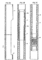
- the tool of the present invention is indicated generally at 10 in Fig. 1 at a subsurface location within a surrounding well casing 11.
- a central mandrel 12 connects to a drill string 13 (Fig. 3) which in turn extends to the well surface (not illustrated).
- the drill string 13 is manipulated from the well surface to position and operate the tool 10.
- the mandrel 12 extends through a tubular spline housing 14 at the upper end of the tool 10.
- the spline housing is secured to a tubular slotted mill housing 15 that is in turn connected at its lower end to an index slot mandrel 16.
- the lower end of the slot mandrel 16 necks down to a cylindrical slot surface section 17 that connects at its end to a mandrel latch section 18.
- a hydraulic seal sub-assembly 19 connects between the mandrel latch section 18 and a tubular mandrel release collet 20.
- the release collet 20 includes multiple collet fingers 21 having collet heads that are held in radial recesses 23 in a surrounding mandrel housing 24.
- the lower end of the housing 24 is surrounded by a dog retaining assembly indicated generally at 25 that employs upper and lower sets of Bellville spring washers 26a to urge contoured orienting and anchoring dogs 27 radially outwardly into engagement with slotted and grooved recesses 28 in the internal surface of an anchoring and orienting sleeve section 29.
- the upper end of the sleeve section 29 is connected to a tubular slip section 30.
- the slip section 30 carries hydraulically set slips 30a and weight set slips 30b that are used to anchor the slip section to the internal wall of the casing 11 to hold the slip section 30 and attached anchoring and orienting section 29 firmly in position within the casing.
- the tool 10 is comprised of four basic tool segments that may be moved longitudinally relative to each other.
- the first tool segment herein referred to as the milling segment, is comprised of the central mandrel 12 that carries a cutting mill 31 at its lower end.
- Splines 12a carried on the mandrel 12 are adapted to be received in slots 32 formed in the spline sleeve 14. (See Fig. 13). When the slots 32 receive the splines 12a, rotation of the mandrel 12 relative to the housing 14 is prevented.
- the second basic tool segment is comprised of the spline housing 14, mill housing 15, index slot mandrel 16, mandrel latch section 18, seal subassembly 19 and mandrel release collet 20.
- the third basic tool segment, or release segment, is comprised of the mandrel housing 24 and dog retaining assembly 25.
- the fourth basic tool segment, or anchor segment is comprised of the anchoring sleeve 29 and the tubular slip section 30.
- the tool 10 is run into the casing with the four basic segments fixed longitudinally relative to each other as best illustrated in Fig. 1.
- This running in configuration holds the slips 30a and 30b and mill 31 in radially retracted positions so that the combined assembly may be moved freely down through the casing 11.
- the tool is oriented with conventional orienting techniques so that the mill 31 is directed toward a selected geographic point.
- the anchor segment is then hydraulically set to hold the tool in place within the casing 11. Setting of the anchor segment is followed by release of temporary holding components that functioned before setting the tool to prevent movement of the tool sections relative to each other. Once released, the milling section may be moved longitudinally and radially to cut the casing wall.
- control segment may be moved longitudinally and angularly to index or shift the mill to a new circumferential cutting area along the casing.
- release segment may be pulled free of the anchor segment to permit retrieval of the assembly comprised of the milling, control and release segments to the well surface.
- the anchor segment remains in place to provide an anchoring and orienting area within the casing that functions to receive, anchor and orient tools or other well equipment lowered into the well for additional work or installation of equipment relative to the casing window.
- the assembly 10 is lowered through the well casing 11 to the desired subsurface location, typically being a point immediately below that at which the casing window is to be formed.
- the tool 10 is oriented circumferentially so that the mill 31 is facing a desired geographic point or area. This may typically be a hydrocarbon bearing formation that is laterally offset from the main well bore.
- the tool is anchored in place within the casing 11 by a sequence of operations commencing with the application of hydrostatic pressure through the drill string 13.
- the hydrostatic pressure communicates from the drill string through the central mandrel 12, through a flexible fluid line 33, through the index slot mandrel 16, through the seal subassembly 19 and through radial ports 34 into the hydraulic setting structure acting on the slips 30a.
- the described setting procedure which is conventional, causes the slips 30a to extend radially outwardly into firm gripping engagement with the internal wall of the casing 11.
- Weight is then applied to the tool 10 through the drill string 13 in a conventional manner to set the slips 30b, which act to prevent upward movement of the tool 10.
- the slips 30a are set with an application of hydrostatic pressure of approximately 103 bar (1500 psi) and the slips 30b are set with the application of approximately 45 kN (10,000 pounds of weight) on the tool 10.
- the hydrostatic pressure in the drill string is increased to approximately 172 bar (2,500 psi) to shear temporary restraining pins and force the hydraulic piston 20a down through the mandrel release collet 20 as best illustrated in Fig. 2.
- This downward shift of the piston 20a displaces the retainer ring 26 away from the collet heads 22 to free the collet (and attached central segment) for longitudinal movement relative to the surrounding release segment (mandrel 24) and anchor segment (slip section 30).
- the mill segment is released by increasing the amount of weight applied to the tool 10 to approximately 90 kN (20,000 pounds), shearing a temporary retaining shear pin holding the central mandrel 12 to the spline housing 14. This action frees the milling segment to move longitudinally relative to the control segment.
- a re-engageable detent 35a secures the central mandrel 12 to the control segment (housing 14).
- a force of approximately 18 kN (4000 pounds) is required to separate the mandrel 12 from the detent.
- the detent is automatically re-engaged with the mandrel 12 each time the spline is moved back to its starting point (illustrated in Fig. 1).
- the drill string 13 is lowered sufficiently to displace splines 12a on the mandrel 12 from receiving slots formed in the slot housing 14 to permit rotation of the mill 31.
- the drill string is then rotated and advanced downwardly to propel the mill 31 along sloped tracks 36 and 37 (see Fig. 13) through a mill housing opening 38 into contact with the surrounding casing wall.
- the mill 31 is supported between the tracks 36 and 37 by front and rear carriage mounts 39 and 40, respectively, that permit rotary motion of the bit while spacing the bit to prevent it from cutting the underlying mill housing.
- the initial rotation of the mill 31 ruptures the hydraulic fluid line 33.
- the mill advances along the sloping tracks 36 and 37, it is slowly advanced into engagement with the casing wall to begin the cut with a minimum of offsetting forces that tend to cause the mill to drift in the direction of the cutting rotation.
- the cut becomes deeper during the initial mill travel, extending through the casing wall and slightly into the cement (not illustrated) or other material surrounding the casing.
- the tracks direct the mill along a path substantially parallel to the axis of the tool 10 to form the major portion of the longitudinal casing cut which, as will be described, cooperates with subsequent longitudinal cuts to form a window 41 through the casing.
- the end of the mill cut is reached when the mill carriage mount 39 engages the end of the mill housing opening 38 as indicated in Fig. 3.
- the second cut of the mill is accomplished by changing the angular position of the control segment (slot section 17) relative to the anchor segment (sleeve 29).
- the angular position of the control segment is changed by selectively lowering, raising and rotating the drill string 13 to advance a slot surface pattern 42 (see Fig. 6) formed on the external cylindrical surface of the slot section 17 over splines 43 positioned within a spline sleeve 44 at the upper end of the mandrel housing 24.
- the slot pattern 42 is configured to produce three separate angular positions of the milling segment (housing 15) relative to the control segment (slot mandrel 16).
- Each of the three angular positions is selected to be approximately 60° from the adjacent section so that, with a suitably sized mill 31, the three cuts combine to form a window of approximately 180° in circumferential development.
- the drill pipe 13 is initially raised until the splines 12a are received within the spline housing latching the detent 35 and then raised further to pull the control segment (slot mandrel 16) up through the release segment (spline sleeve 44).
- the milling segment is releasably secured to the control segment by spring loaded dogs 45 that mesh with recesses 46 or 47, formed on the mandrel latch section 18.
- the spring loading is imposed by a set of Bellville springs 48 that cooperate with tapered bearing surfaces to urge the dogs 45 radially inwardly against the mandrel latch section 18.
- the dogs 45 and recesses 46 and 47 have matching tapered contours that permit the dogs to be displaced longitudinally from the recesses when sufficient longitudinal force is exerted between the two components.
- an upward force of approximately 36 kN (8,000 pounds) is required to displace the dogs 45 upwardly from their engagement with the recess 46 or 47.
- a downward force on the control segment of approximately only 4 kN (2000 pounds) is required to displace the dogs 45 downwardly from the recesses 46 or 47.
- the milling segment (slot mandrel 16 and slot surface section 17) are free to move up until the recesses 46 and 47 have passed the dogs 45 and a shoulder 42a in slot 1 of the slot pattern engages the splines 43.
- the shoulder engagement is noted by a change in lifting force in the drill string 13 above the 36 kN (8000 pound force) required to move the two recesses 46 and 47 past the dogs 45.
- the drill string is torqued to the right to shift the lower end of slot 1 over the splines 43 to allow the mill segment to be moved relative to the splines 43 into the relative position illustrated by the dotted line representation 43a of the splines 43.
- the drill string is then lowered while maintaining a right hand torque so that the slot pattern 42 advances over the splines 43 to move into the relative position indicated by the dotted line spline representation 43b.
- the dogs 45 are landed in the recess 46 to temporarily hold the milling assembly (mill housing 15) fixed relative to the control assembly (housing 24) during the formation of the second mill cut.
- the longitudinal position of the mill segment is higher when the mill segment is indexed in its second cut (spline in position 43b) to provide a window having a high center top opening.
- the drill string 13 With the milling segment and control segment thus aligned, the drill string 13 is lowered to release the detent 35a and move the splines 12a out of the spline housing 14. The drill string 13 is then lowered and rotated, as described previously, to cut a second cut in the casing wall to form a partial window as indicated in Fig. 11. Following completion of the second cut, the described sequence of drill pipe movement and torque is repeated to index the tool for the third cut to complete the window 41 as indicated in Fig. 12.
- the milling segment, control segment and release segment are retrieved to the well surface as a unit. This is effected by exerting an upward pull on the drill string that pulls the dogs 27 free of the anchor recesses 28. An upward force of approximately 112.5 kN (25,000 pounds) is required to release the dogs.
- the anchor segment, illustrated in Fig. 7, remains fixed in place below the window 41 to be used at a later time for holding and orienting a whipstock or other subsurface tool or equipment that may be required to drill complete or workover the well.
- the tubular opening through anchor segment allows ready access to the well casing below the anchor.
- FIG 14 illustrates a modified form of the anchoring assembly, indicated generally at 100, that may be employed with the present invention.
- the assembly 100 is comprised of a casing coupling 101 having a pattern of slots S and grooves G that are adapted to mate with corresponding contours formed on the dogs 27 of the anchoring segment of the invention.
- the coupling 101 as more fully described in the related application hereinbefore identified, is placed in the casing string of a well when the well is initially drilled.
- the pattern and placement of the slots and grooves in the coupling 101 function similarly to those within the anchoring segment (sleeve 29) described in the first form of the invention.
- the assembly substantially as retrieved from the set anchor segment of the previous embodiment is run into the well and landed in the coupling 101.
- the advantage of equipping the well with a coupling such as the coupling 101 is that the anchoring and orienting functions required for milling a casing window may be provided with a device that permits a fully open, or full drift, casing.
Claims (27)
- Outil (10) destiné à réaliser une fenêtre souterraine (41) dans la paroi d'un tubage de puits s'étendant longitudinalement (11) comprenant :un ensemble de coupe (12, 31) destiné à découper de multiples ouvertures espacées le long de la circonférence et s'étendant longitudinalement dans ledit tubage de puits ;un mécanisme d'ancrage (29, 30) destiné à l'ancrage dudit ensemble de coupe sur la surface interne de la paroi dudit tubage de puits à un emplacement défini du puits souterrain ;une structure de mise en place par glissement (30a, 30b) susceptible d'être mise en oeuvre une fois en place pour engager et accrocher ledit mécanisme d'ancrage à l'intérieur dudit tubage de puits à un emplacement souterrain, ledit mécanisme d'ancrage ayant une orientation définie par rapport à un point géographique choisi ; et,un dispositif d'indexation (14, 15, 16, 18, 19, 20) reliant ledit ensemble de coupe (12, 31) et ladite structure de mise en place par glissement (30) afin de modifier l'emplacement le long de la circonférence à l'intérieur dudit tubage (11) desdites ouvertures s'étendant longitudinalement, ce par quoi une fenêtre (41) est réalisée au travers de ladite paroi de tubage au moyen d'ouvertures adjacentes combinées réalisées au moyen dudit dispositif de coupe.
- Outil selon la revendication 1, comprenant, en outre :une structure de libération (24, 25) reliant ladite structure de mise en place par glissement (30) audit ensemble de coupe (12, 31), afin de libérer de manière sélective ledit ensemble de coupe (12, 31), pour le retrait, de ladite structure de mise en place par glissement, après que ladite structure de mise en place est positionnée ; et,une chemise d'orientation et d'ancrage (29) placée dans ladite structure de mise en place par glissement, susceptible d'être mise en oeuvre après libération et retrait dudit ensemble de coupe (12, 31), ladite chemise (29) comprenant un ensemble tubulaire (30) concentrique audit tubage de puits (11) et munie de contours internes de paroi, destinés à l'ancrage et à l'orientation de l'équipement de puits dans ledit tubage à un emplacement prédéterminé par rapport à ladite fenêtre (41).
- Outil selon la revendication 1 ou la revendication 2, dans lequel ledit ensemble de coupe (12, 31) comprend en outre un chariot (39, 40) destiné à supporter un dispositif des mouvements de coupe pour assurer des mouvements de rotation et de translation longitudinale et radiale dans ledit tubage.
- Outil selon la revendication 3, comprenant en outre une section de support de rail incliné (36, 37) destinée audit chariot pour réaliser une coupe de profondeur croissante dans ladite paroi de tubage au fur et à mesure de l'avance dudit dispositif de coupe le long dudit support de rail incliné.
- Outil selon la revendication 3 ou la revendication 4, comprenant en outre des doubles supports de rail (36, 37) destinés au montage dudit chariot avec ledit dispositif de coupe disposé de manière centrale entre lesdits doubles supports de rail.
- Outil selon la revendication 5, dans lequel au moins une partie dudit double support de rail présente une pente s'écartant de l'axe central dudit tubage.
- Outil selon l'une quelconque des revendications précédentes, comprenant en outre une structure de libération actionnée de manière hydraulique (24, 25) reliant ladite structure de mise en place par glissement (30) audit ensemble de coupe afin de libérer de manière sélective ledit ensemble de coupe (12, 31), pour le retrait, de ladite structure de mise en place par glissement (30) après le positionnement de ladite structure de mise en place.
- Outil selon l'une quelconque des revendications précédentes, comprenant en outre :des mécanismes d'accrochage actionnés de manière hydraulique (30a) placés dans ladite structure de mise en place par glissement, susceptibles d'être mis en oeuvre lors d'une action destinée à prévenir le mouvement descendant de ladite structure de mise en place par glissement (30) dans ledit tubage de puits ; et,des mécanismes d'accrochage actionnés par gravité (30b) susceptibles d'être mis en oeuvre après actionnement desdits mécanismes actionnés de manière hydraulique pour éviter le mouvement ascendant de ladite structure de mise en place par glissement (30) dans ledit tubage de puits (11).
- Système destiné à former une fenêtre souterraine dans la paroi d'un tubage de puits s'étendant longitudinalement (11) comprenant :dans lequel ledit ensemble de coupe (12, 31) permet de découper une fenêtre dans ledit tubage à un deuxième emplacement souterrain ;un outil (10) selon la revendication 1 ;une zone d'ancrage positionnée à un premier emplacement souterrain le long de la surface interne dudit tubage de puits (11) ; et,un système d'orientation ;
dans lequel ledit mécanisme d'ancrage (29, 30) est relié audit ensemble de coupe (12, 31) afin d'assurer sélectivement l'engagement et l'ancrage dudit ensemble de coupe dans ladite zone d'ancrage pour maintenir ledit ensemble de coupe pendant que ladite fenêtre est découpée dans ledit tubage ;
dans lequel ledit système d'orientation est destiné à orienter ledit ensemble de coupe (12, 31) par rapport audit point géographique défini, ce qui permet la découpe de ladite fenêtre au niveau d'une position connue de la circonférence, dans ledit tubage (11) ;
dans lequel un mécanisme de coupe est porté dans ledit ensemble de coupe (12, 31) afin de réaliser une première coupe s'étendant longitudinalement au travers dudit tubage (11) au niveau dudit deuxième emplacement souterrain ; et,
dans lequel ledit dispositif d'indexation (14, 15, 16, 18, 19, 20) sert à modifier la position circonférentielle dudit mécanisme de coupe pour réaliser une deuxième découpe s'étendant longitudinalement au travers dudit tubage, ladite deuxième découpe étant adjacente à ladite première découpe ce qui permet de combiner lesdites première et deuxième découpes pour former une fenêtre à travers ledit tubage. - Système selon la revendication 9, dans lequel ledit dispositif d'indexation (14, 15, 16, 18, 19, 20) modifie la position circonférentielle dudit mécanisme de coupe (12, 31) par rapport audit mécanisme d'ancrage (29, 30).
- Système selon la revendication 9 ou la revendication 10, dans lequel ledit mécanisme d'ancrage (29, 30) comprend un couplage de tubage reliant ensemble des sections dudit tubage.
- Système selon la revendication 11, dans lequel ledit couplage de tubage comprend une surface interne munie de contours multiples, adaptée pour s'engager dans et s'accoupler avec des contours correspondants dudit mécanisme d'ancrage afin d'ancrer et d'orienter ledit ensemble de coupe.
- Système selon l'une quelconque des revendications 9 à 12, comprenant en outre une structure de libération (24, 25) dans ledit mécanisme d'ancrage (29, 30) destinée à libérer ledit mécanisme d'ancrage (29, 30) et ledit ensemble de coupe (12, 31) de ladite zone d'ancrage après réalisation de ladite fenêtre.
- Système selon la revendication 13 dans lequel ladite zone d'ancrage comprend un couplage reliant ensemble des sections dudit tubage.
- Outil ou système selon l'une quelconque des revendications 9 à 14, dans lequel ledit mécanisme de coupe comprend une fraiseuse circulaire (31).
- Système selon la revendication 15, comprenant en outre :un chariot (39, 40) destiné à supporter ladite fraiseuse circulaire pour assurer des mouvements de rotation et de translation longitudinale et radiale par rapport audit tubage ; et,un rail (36, 37) porté par ledit ensemble de coupe (12, 31) et muni d'une section inclinée destinée à déplacer ledit chariot (39, 40) radialement au fur et à mesure du déplacement dudit chariot longitudinalement sur ledit rail, ledit rail étant configuré pour supporter ledit chariot (39, 40) et ladite fraiseuse (31), ce qui permet à ladite fraiseuse de découper ledit tubage sans découper ledit ensemble de coupe (12, 31).
- Procédé de formation d'une fenêtre souterraine (41) dans un tubage de puits (11) comprenant les étapes consistant à :placer un outil de coupe (31) à un emplacement souterrain souhaité dans un tubage de puits (11) ;orienter l'outil dans une première position de coupe ;découper une première ouverture s'étendant longitudinalement à travers la paroi dudit tubage au niveau de ladite première position de coupe ;déplacer l'outil dans une deuxième position de coupe espacée, le long de la circonférence, de ladite première position de coupe ;découper une deuxième ouverture s'étendant longitudinalement à travers la paroi du tubage au niveau d'une deuxième position de coupe, ladite deuxième ouverture étant adjacente à ladite première ouverture pour former une ouverture combinée ayant une portée plus importante le long de la circonférence que celle, soit de ladite première, soit de ladite deuxième ouverture ; et,extraire l'outil de coupe (31) jusqu'à la surface du puits.
- Procédé selon la revendication 17, comprenant en outre les étapes consistant à :ancrer l'outil de coupe dans le tubage au moyen d'un dispositif d'ancrage et d'orientation (29, 30) ; et,séparer l'outil de coupe du dispositif d'ancrage et d'orientation.
- Procédé selon la revendication 18, comprenant en outre l'étape consistant à placer le dispositif d'ancrage et d'orientation dans le tubage de puits pendant la mise en place de l'outil de coupe (31).
- Procédé selon l'une quelconque des revendications 17 à 19, comprenant en outre l'étape consistant à déplacer un élément de coupe dans l'outil de coupe vers différentes positions circonférentielles par rapport à l'outil afin de découper lesdites ouvertures s'étendant longitudinalement.
- Procédé selon la revendication 20, comprenant en outre l'étape consistant à déplacer l'outil de coupe vers trois positions de découpe différentes espacées approximativement de 60° les unes des autres pour réaliser une fenêtre de tubage ayant une portée d'environ 180° le long de la circonférence.
- Procédé selon la revendication 17, comprenant en outre les étapes consistant à :verrouiller l'outil de coupe (31) au niveau de ladite première position de découpe pour éviter le déplacement circonférentiel de l'outil par rapport au tubage (11);libérer l'outil de coupe de sa position verrouillée au niveau de ladite première position de coupe ;déplacer l'outil de coupe vers ladite deuxième position de coupe ; et,verrouiller l'outil dans ladite deuxième position de coupe pour éviter le déplacement circonférentiel de l'outil par rapport au tubage.
- Procédé selon la revendication 22, incluant en outre les étapes consistant à assurer la rotation et le déplacement longitudinal de l'outil de coupe pour verrouiller et libérer l'outil au niveau desdites première et deuxième positions de coupe.
- Procédé selon la revendication 17, comprenant en outre les étapes consistant à :ancrer l'outil de coupe dans le tubage au moyen d'un dispositif d'ancrage et d'orientation (29, 30) ; et,mettre en place le dispositif d'ancrage et d'orientation par pression hydraulique et gravité pour éviter le déplacement longitudinal du dispositif d'ancrage et d'orientation (29, 30) dans le tubage de puits.
- Procédé selon la revendication 18 ou la revendication 19, comprenant en outre l'étape consistant à orienter l'équipement de puits au moyen du dispositif d'ancrage et d'orientation, ce qui permet de mettre en oeuvre les procédures d'orientation de-puits souterrain au moyen de l'équipement de puits.
- Procédé selon la revendication 19 ou la revendication 25, comprenant en outre l'étape consistant à ancrer l'équipement de puits au moyen du dispositif d'ancrage et d'orientation (29, 30).
- Procédé selon la revendication 22, comprenant en outre les étapes consistant à :contraindre l'outil de coupe en position fixe dans le sens longitudinal au niveau des première et deuxième positions longitudinales dans le tubage pendant qu'une tête de coupe placée dans ledit outil se déplace longitudinalement par rapport au tubage ; et,s'opposer à la contrainte appliquée sur ledit outil de coupe pour déplacer l'outil longitudinalement dans le tubage.
Applications Claiming Priority (3)
| Application Number | Priority Date | Filing Date | Title |
|---|---|---|---|
| US654984 | 1996-05-29 | ||
| US08/654,984 US5778980A (en) | 1996-05-29 | 1996-05-29 | Multicut casing window mill and method for forming a casing window |
| PCT/US1997/009182 WO1997045619A1 (fr) | 1996-05-29 | 1997-05-22 | Fraise a plusieurs decoupes constituant une fenetre |
Publications (3)
| Publication Number | Publication Date |
|---|---|
| EP0901559A1 EP0901559A1 (fr) | 1999-03-17 |
| EP0901559A4 EP0901559A4 (fr) | 2002-03-20 |
| EP0901559B1 true EP0901559B1 (fr) | 2004-07-14 |
Family
ID=24627010
Family Applications (1)
| Application Number | Title | Priority Date | Filing Date |
|---|---|---|---|
| EP97926806A Expired - Lifetime EP0901559B1 (fr) | 1996-05-29 | 1997-05-22 | Fraise a plusieurs decoupes constituant une fenetre |
Country Status (6)
| Country | Link |
|---|---|
| US (1) | US5778980A (fr) |
| EP (1) | EP0901559B1 (fr) |
| AU (1) | AU3148297A (fr) |
| CO (1) | CO4700358A1 (fr) |
| NO (1) | NO315172B1 (fr) |
| WO (1) | WO1997045619A1 (fr) |
Families Citing this family (21)
| Publication number | Priority date | Publication date | Assignee | Title |
|---|---|---|---|---|
| US6209636B1 (en) | 1993-09-10 | 2001-04-03 | Weatherford/Lamb, Inc. | Wellbore primary barrier and related systems |
| US6283208B1 (en) * | 1997-09-05 | 2001-09-04 | Schlumberger Technology Corp. | Orienting tool and method |
| CA2248287C (fr) * | 1998-09-22 | 2002-05-21 | Laurier E. Comeau | Coupleur a surete integree pour dispositif de verrouillage |
| US6318466B1 (en) | 1999-04-16 | 2001-11-20 | Schlumberger Technology Corp. | Method and apparatus for accurate milling of windows in well casings |
| US6209645B1 (en) | 1999-04-16 | 2001-04-03 | Schlumberger Technology Corporation | Method and apparatus for accurate milling of windows in well casings |
| US6267179B1 (en) | 1999-04-16 | 2001-07-31 | Schlumberger Technology Corporation | Method and apparatus for accurate milling of windows in well casings |
| US6474415B1 (en) * | 2000-11-15 | 2002-11-05 | Schlumberger Technology Corporation | Method and apparatus for milling openings in downhole structures |
| US6715567B2 (en) | 2001-05-02 | 2004-04-06 | Weatherford/Lamb, Inc. | Apparatus and method for forming a pilot hole in a formation |
| US6568480B2 (en) * | 2001-05-03 | 2003-05-27 | Smith International, Inc. | Orientation and locator system and method of use |
| DE10325684B4 (de) * | 2003-06-02 | 2005-07-28 | Siemens Ag | Schalteranordnung |
| US7661477B2 (en) * | 2006-03-31 | 2010-02-16 | Schlumberger Technology Corporation | System and method for unsticking a tool stuck in a wellbore |
| US7607478B2 (en) * | 2006-04-28 | 2009-10-27 | Schlumberger Technology Corporation | Intervention tool with operational parameter sensors |
| US7540327B2 (en) * | 2006-04-28 | 2009-06-02 | Schlumberger Technology Corporation | Abrasive jet cutting system and method for cutting wellbore tubulars |
| MX342598B (es) | 2009-12-23 | 2016-10-06 | Schlumberger Tech B V * | Colocacion hidraulica de un mecanismo de aislamiento de pozo. |
| CN104428482B (zh) | 2012-07-03 | 2017-03-08 | 哈利伯顿能源服务公司 | 通过第二井眼交叉第一井眼的方法 |
| SG11201407865YA (en) * | 2012-07-11 | 2014-12-30 | Halliburton Energy Services Inc | Systems and methods for managing milling debris |
| MX358887B (es) | 2013-01-18 | 2018-08-29 | Halliburton Energy Services Inc | Sistemas y metodos para sostener una ventana multilateral. |
| CN103334711B (zh) * | 2013-06-17 | 2015-09-23 | 中国石油集团长城钻探工程有限公司 | 电控井下套管开窗工具 |
| BR112016013177B1 (pt) * | 2013-12-31 | 2021-05-18 | Halliburton Energy Services, Inc | sistema, e, método para fresagem de revestimento |
| CN111206896B (zh) * | 2020-03-06 | 2021-07-23 | 西华大学 | 一种机械液压双作用导斜器锚定工具 |
| US20230138954A1 (en) * | 2021-11-02 | 2023-05-04 | Baker Hughes Oilfield Operations Llc | Hydrostatic module interlock, method and system |
Family Cites Families (14)
| Publication number | Priority date | Publication date | Assignee | Title |
|---|---|---|---|---|
| US3908759A (en) * | 1974-05-22 | 1975-09-30 | Standard Oil Co | Sidetracking tool |
| EP0353962A3 (fr) * | 1988-07-30 | 1991-03-27 | Tri-State Oil Tool (UK), a division of Baker Hughes Limited | Outil pour couper les tubages |
| US5035292A (en) * | 1989-01-11 | 1991-07-30 | Masx Energy Service Group, Inc. | Whipstock starter mill with pressure drop tattletale |
| GB9003047D0 (en) * | 1990-02-10 | 1990-04-11 | Tri State Oil Tool Uk | Insert type window mill |
| US5154231A (en) * | 1990-09-19 | 1992-10-13 | Masx Energy Services Group, Inc. | Whipstock assembly with hydraulically set anchor |
| US5193620A (en) * | 1991-08-05 | 1993-03-16 | Tiw Corporation | Whipstock setting method and apparatus |
| US5322127C1 (en) * | 1992-08-07 | 2001-02-06 | Baker Hughes Inc | Method and apparatus for sealing the juncture between a vertical well and one or more horizontal wells |
| US5301760C1 (en) * | 1992-09-10 | 2002-06-11 | Natural Reserve Group Inc | Completing horizontal drain holes from a vertical well |
| US5277251A (en) * | 1992-10-09 | 1994-01-11 | Blount Curtis G | Method for forming a window in a subsurface well conduit |
| US5335737A (en) * | 1992-11-19 | 1994-08-09 | Smith International, Inc. | Retrievable whipstock |
| US5467819A (en) * | 1992-12-23 | 1995-11-21 | Tiw Corporation | Orientable retrievable whipstock and method of use |
| CA2095306A1 (fr) * | 1993-04-30 | 1994-10-31 | Michael Robert Konopczynski | Dispositif de demarrage auxiliaire au percage |
| US5439051A (en) * | 1994-01-26 | 1995-08-08 | Baker Hughes Incorporated | Lateral connector receptacle |
| US5592991A (en) * | 1995-05-31 | 1997-01-14 | Baker Hughes Inc. | Method and apparatus of installing a whipstock |
-
1996
- 1996-05-29 US US08/654,984 patent/US5778980A/en not_active Expired - Lifetime
-
1997
- 1997-05-22 WO PCT/US1997/009182 patent/WO1997045619A1/fr active IP Right Grant
- 1997-05-22 EP EP97926806A patent/EP0901559B1/fr not_active Expired - Lifetime
- 1997-05-22 AU AU31482/97A patent/AU3148297A/en not_active Abandoned
- 1997-05-29 CO CO97029948A patent/CO4700358A1/es unknown
-
1998
- 1998-11-27 NO NO19985556A patent/NO315172B1/no not_active IP Right Cessation
Also Published As
| Publication number | Publication date |
|---|---|
| NO985556L (no) | 1999-01-27 |
| NO985556D0 (no) | 1998-11-27 |
| NO315172B1 (no) | 2003-07-21 |
| EP0901559A1 (fr) | 1999-03-17 |
| CO4700358A1 (es) | 1998-12-29 |
| AU3148297A (en) | 1998-01-05 |
| WO1997045619A1 (fr) | 1997-12-04 |
| EP0901559A4 (fr) | 2002-03-20 |
| US5778980A (en) | 1998-07-14 |
Similar Documents
| Publication | Publication Date | Title |
|---|---|---|
| EP0901559B1 (fr) | Fraise a plusieurs decoupes constituant une fenetre | |
| EP1153195B1 (fr) | Appareil et procede fond-de-trou permettant de percer une fenetre et au moins un chemin de clavette dans un tubage de puits | |
| CA2164774C (fr) | Appareil de coupe recuperable et methode connexe | |
| US6619400B2 (en) | Apparatus and method to complete a multilateral junction | |
| US5467819A (en) | Orientable retrievable whipstock and method of use | |
| US5954130A (en) | Retrievable milling guide anchor apparatus and associated methods | |
| US5335737A (en) | Retrievable whipstock | |
| US5924491A (en) | Thru-tubing anchor seal assembly and/or packer release devices | |
| EP0701042B1 (fr) | Procédé et dispositif de décentrage, notamment pour puits avec plusieurs forages latéraux | |
| US7997336B2 (en) | Method and apparatus for retrieving an assembly from a wellbore | |
| JPH04231591A (ja) | ホイップストック組立体及びその走行及び固定方法 | |
| US6554062B1 (en) | Anchor apparatus and method | |
| WO1999064713A1 (fr) | Outil de forage | |
| WO1993003252A1 (fr) | Procede et dispositif de reglage d'un biseau de deviation | |
| USRE36526E (en) | Retrievable through tubing tool and method | |
| CA2308846C (fr) | Troncon de petit diametre dans le sifflet deviateur et methode de mise en place d'un tubage de grand diametre | |
| WO1995023274A1 (fr) | Dispositif et procede de recuperation d'un sifflet deviateur | |
| CA2391678C (fr) | Methode et appareil de fraisage pour un puits | |
| AU2018434354B2 (en) | Method and apparatus for introducing a junction assembly |
Legal Events
| Date | Code | Title | Description |
|---|---|---|---|
| PUAI | Public reference made under article 153(3) epc to a published international application that has entered the european phase |
Free format text: ORIGINAL CODE: 0009012 |
|
| 17P | Request for examination filed |
Effective date: 19981201 |
|
| AK | Designated contracting states |
Kind code of ref document: A1 Designated state(s): GB NL |
|
| A4 | Supplementary search report drawn up and despatched |
Effective date: 20020205 |
|
| AK | Designated contracting states |
Kind code of ref document: A4 Designated state(s): GB NL |
|
| 17Q | First examination report despatched |
Effective date: 20021125 |
|
| RAP1 | Party data changed (applicant data changed or rights of an application transferred) |
Owner name: HALLIBURTON ENERGY SERVICES, INC. |
|
| GRAP | Despatch of communication of intention to grant a patent |
Free format text: ORIGINAL CODE: EPIDOSNIGR1 |
|
| GRAS | Grant fee paid |
Free format text: ORIGINAL CODE: EPIDOSNIGR3 |
|
| GRAA | (expected) grant |
Free format text: ORIGINAL CODE: 0009210 |
|
| AK | Designated contracting states |
Kind code of ref document: B1 Designated state(s): GB NL |
|
| REG | Reference to a national code |
Ref country code: GB Ref legal event code: FG4D |
|
| PLBE | No opposition filed within time limit |
Free format text: ORIGINAL CODE: 0009261 |
|
| STAA | Information on the status of an ep patent application or granted ep patent |
Free format text: STATUS: NO OPPOSITION FILED WITHIN TIME LIMIT |
|
| 26N | No opposition filed |
Effective date: 20050415 |
|
| PGFP | Annual fee paid to national office [announced via postgrant information from national office to epo] |
Ref country code: NL Payment date: 20060424 Year of fee payment: 10 |
|
| PG25 | Lapsed in a contracting state [announced via postgrant information from national office to epo] |
Ref country code: NL Free format text: LAPSE BECAUSE OF NON-PAYMENT OF DUE FEES Effective date: 20071201 |
|
| NLV4 | Nl: lapsed or anulled due to non-payment of the annual fee |
Effective date: 20071201 |
|
| PGFP | Annual fee paid to national office [announced via postgrant information from national office to epo] |
Ref country code: GB Payment date: 20160408 Year of fee payment: 20 |
|
| REG | Reference to a national code |
Ref country code: GB Ref legal event code: PE20 Expiry date: 20170521 |
|
| PG25 | Lapsed in a contracting state [announced via postgrant information from national office to epo] |
Ref country code: GB Free format text: LAPSE BECAUSE OF EXPIRATION OF PROTECTION Effective date: 20170521 |