EP0901423B1 - Motor vehicle power train - Google Patents
Motor vehicle power train Download PDFInfo
- Publication number
- EP0901423B1 EP0901423B1 EP97926093A EP97926093A EP0901423B1 EP 0901423 B1 EP0901423 B1 EP 0901423B1 EP 97926093 A EP97926093 A EP 97926093A EP 97926093 A EP97926093 A EP 97926093A EP 0901423 B1 EP0901423 B1 EP 0901423B1
- Authority
- EP
- European Patent Office
- Prior art keywords
- change speed
- speed transmission
- power train
- pair
- transmission
- Prior art date
- Legal status (The legal status is an assumption and is not a legal conclusion. Google has not performed a legal analysis and makes no representation as to the accuracy of the status listed.)
- Expired - Lifetime
Links
- 230000005540 biological transmission Effects 0.000 claims abstract description 118
- 230000008859 change Effects 0.000 claims abstract description 80
- 230000008878 coupling Effects 0.000 claims description 4
- 238000010168 coupling process Methods 0.000 claims description 4
- 238000005859 coupling reaction Methods 0.000 claims description 4
- 230000007246 mechanism Effects 0.000 description 4
- 230000004048 modification Effects 0.000 description 3
- 238000012986 modification Methods 0.000 description 3
- 238000004806 packaging method and process Methods 0.000 description 3
- 239000010687 lubricating oil Substances 0.000 description 2
- 239000000725 suspension Substances 0.000 description 2
- 230000004308 accommodation Effects 0.000 description 1
- 230000008901 benefit Effects 0.000 description 1
- 230000003197 catalytic effect Effects 0.000 description 1
- 238000010276 construction Methods 0.000 description 1
- 230000007423 decrease Effects 0.000 description 1
- 230000009467 reduction Effects 0.000 description 1
Images
Classifications
-
- B—PERFORMING OPERATIONS; TRANSPORTING
- B60—VEHICLES IN GENERAL
- B60K—ARRANGEMENT OR MOUNTING OF PROPULSION UNITS OR OF TRANSMISSIONS IN VEHICLES; ARRANGEMENT OR MOUNTING OF PLURAL DIVERSE PRIME-MOVERS IN VEHICLES; AUXILIARY DRIVES FOR VEHICLES; INSTRUMENTATION OR DASHBOARDS FOR VEHICLES; ARRANGEMENTS IN CONNECTION WITH COOLING, AIR INTAKE, GAS EXHAUST OR FUEL SUPPLY OF PROPULSION UNITS IN VEHICLES
- B60K17/00—Arrangement or mounting of transmissions in vehicles
- B60K17/34—Arrangement or mounting of transmissions in vehicles for driving both front and rear wheels, e.g. four wheel drive vehicles
- B60K17/344—Arrangement or mounting of transmissions in vehicles for driving both front and rear wheels, e.g. four wheel drive vehicles having a transfer gear
- B60K17/346—Arrangement or mounting of transmissions in vehicles for driving both front and rear wheels, e.g. four wheel drive vehicles having a transfer gear the transfer gear being a differential gear
-
- B—PERFORMING OPERATIONS; TRANSPORTING
- B60—VEHICLES IN GENERAL
- B60K—ARRANGEMENT OR MOUNTING OF PROPULSION UNITS OR OF TRANSMISSIONS IN VEHICLES; ARRANGEMENT OR MOUNTING OF PLURAL DIVERSE PRIME-MOVERS IN VEHICLES; AUXILIARY DRIVES FOR VEHICLES; INSTRUMENTATION OR DASHBOARDS FOR VEHICLES; ARRANGEMENTS IN CONNECTION WITH COOLING, AIR INTAKE, GAS EXHAUST OR FUEL SUPPLY OF PROPULSION UNITS IN VEHICLES
- B60K17/00—Arrangement or mounting of transmissions in vehicles
- B60K17/04—Arrangement or mounting of transmissions in vehicles characterised by arrangement, location or kind of gearing
- B60K17/06—Arrangement or mounting of transmissions in vehicles characterised by arrangement, location or kind of gearing of change-speed gearing
- B60K17/08—Arrangement or mounting of transmissions in vehicles characterised by arrangement, location or kind of gearing of change-speed gearing of mechanical type
-
- B—PERFORMING OPERATIONS; TRANSPORTING
- B60—VEHICLES IN GENERAL
- B60K—ARRANGEMENT OR MOUNTING OF PROPULSION UNITS OR OF TRANSMISSIONS IN VEHICLES; ARRANGEMENT OR MOUNTING OF PLURAL DIVERSE PRIME-MOVERS IN VEHICLES; AUXILIARY DRIVES FOR VEHICLES; INSTRUMENTATION OR DASHBOARDS FOR VEHICLES; ARRANGEMENTS IN CONNECTION WITH COOLING, AIR INTAKE, GAS EXHAUST OR FUEL SUPPLY OF PROPULSION UNITS IN VEHICLES
- B60K17/00—Arrangement or mounting of transmissions in vehicles
- B60K17/22—Arrangement or mounting of transmissions in vehicles characterised by arrangement, location, or type of main drive shafting, e.g. cardan shaft
-
- B—PERFORMING OPERATIONS; TRANSPORTING
- B60—VEHICLES IN GENERAL
- B60K—ARRANGEMENT OR MOUNTING OF PROPULSION UNITS OR OF TRANSMISSIONS IN VEHICLES; ARRANGEMENT OR MOUNTING OF PLURAL DIVERSE PRIME-MOVERS IN VEHICLES; AUXILIARY DRIVES FOR VEHICLES; INSTRUMENTATION OR DASHBOARDS FOR VEHICLES; ARRANGEMENTS IN CONNECTION WITH COOLING, AIR INTAKE, GAS EXHAUST OR FUEL SUPPLY OF PROPULSION UNITS IN VEHICLES
- B60K5/00—Arrangement or mounting of internal-combustion or jet-propulsion units
- B60K5/02—Arrangement or mounting of internal-combustion or jet-propulsion units with the engine main axis, e.g. crankshaft axis, substantially in or parallel to the longitudinal centre line of the vehicle
Definitions
- the invention relates to a motor vehicle power trains and is particularly concerned with a power trains of four wheel drive vehicles of the type which have a longitudinally mounted engine.
- a power train in accordance with the features of the preamble of claim 1 is known from US-A-4 805 720.
- Known power trains of conventional four wheel drive vehicles typically comprise a change speed transmission mounted axially in line with the engine and a transfer transmission which is mounted directly on the change speed transmission to drive front and rear differentials through propshafts offset from the engine and the change speed transmission.
- a separate transfer transmission is spaced from the change speed transmission and connected to it through a short universally jointed propshaft.
- an object of the present invention is to provide a motor vehicle power train which helps to optimise the available space.
- a power train for a motor vehicle having a pair of front wheels and a pair of rear wheels
- the power train comprising an engine which, in use, is mounted longitudinally in the vehicle, a change speed transmission drivably connected to the engine, a front differential disposed, in use, between the front wheels and drivably connected thereto, a rear differential disposed, in use, between the rear wheels and drivably connected thereto and a transfer transmission mounted on the change speed transmission and drivably connected to the front differential through a front propshaft and to the rear differential through a rear propshaft, the change speed transmission having an input shaft arranged to receive drive from the engine at one end of the change speed transmission and an output shaft axially offset from the input shaft and having a drive output at the opposite end of the change speed transmission, the transfer transmission being arranged at said opposite end of the change speed transmission for receiving the drive output therefrom and including a centre differential having differential output shafts drivably connected to the front and rear propshafts and
- the change speed transmission includes constant mesh gear trains each comprising a pair of gears, one gear of each pair being mounted on the input shaft and the other of each pair being mounted on the output shaft, in which case one gear of each pair may be fixed to or integral with the input shaft, the other gear of each pair being selectably connected to the output shaft.
- the transfer transmission may includes constant mesh gear trains each comprising a pair of gears, one gear of each pair being mounted on the output shaft and the other of each pair being mounted on the centre differential, in which case said one gear of each pair may be fixed to or integral with the centre differential, the other gear of each pair being selectably connected to the output shaft.
- a drive coupling such as a clutch or torque converter may be mounted on the engine and the input propshaft be interposed between the drive coupling and the input shaft of the change speed transmission.
- a change speed transmission used in the present invention can be based on one which has been initially designed for use on front wheel drive motor cars with transverse engines. Such transmissions have been increasingly popular since about 1960. Since then, most drive lines have comprised a change speed transmission mounted in line with the engine, an input shaft of the transmission being axially aligned with the engine and an output shaft being parallel with and spaced from the input shaft with the input shaft and the output shaft both extending from the change speed transmission at the same end.
- the output shaft has a gear which directly drives a gear mounted on a cage of a differential mounted on the rear of the change speed transmission, the differential having drive shafts directly connected to the front wheels.
- the change speed transmission used in the conventional type of four wheel drive power trains described above was usually able to use a casing, rotary drive components and selector components substantially identical to those produced for the change speed transmission used for conventional front engine, rear wheel drive motor vehicles where the change speed transmission was directly connected to a rear axle through a longitudinal propshaft.
- the production of new designs of change speed transmission for such conventional drive arrangements is becoming increasingly rare as change speed transmissions are designed and developed for the large numbers of vehicles now produced with transverse engines.
- the change speed transmission used in the power train in accordance with the invention preferably includes a casing, rotary drive components and selector components substantially identical to those produced for a change speed transmission used in a front wheel drive motor vehicle where the change speed transmission has a drive input shaft and a drive output shaft extending from the same end of the change speed transmission, the change speed transmission having been modified to position the drive input shaft at the opposite end to the drive output shaft for receiving drive from the input propshaft.
- Such an arrangement is particularly advantageous as a known type of front wheel drive change speed transmission can be used and modified to position its drive input shaft at the opposite end from that for which the transmission was designed. In practice, such a modification is fairly straightforward as it will leave the internal selector components and gear trains unchanged thereby minimising the cost of the change speed transmission.
- the transfer gearing is positioned substantially midway between the front and rear differentials.
- the front and rear propshafts can be made of substantially equal length.
- a motor vehicle which incorporates a power train according to said one aspect of the invention.
- the change speed transmission can be housed partly within a tunnel formed in a floor of the motor vehicle in which it is installed.
- the tunnel projects upwardly into the interior of the vehicle between foot wells for front and rear passengers so as not to intrude into either of the foot wells.
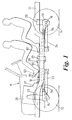
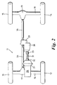
- a motor vehicle 11 includes a pair of front wheels 12, 13 and a pair of rear wheels 14, 15.
- the front wheels 12, 13 are carried by a front axle 16 having a differential unit 17.
- the rear wheels 14, 15 are carried by a rear axle 18 having a differential 19.
- the front axle 17 is suspended from a vehicle chassis 21 by means of leading links 22 and coil springs 23.
- the rear axle 18 is suspended from the chassis 21 by means of trailing links 24 and air springs 25.
- the front and rear axles 16, 18 form part of a power train which also includes an engine 26, a bell housing 27 which covers a flywheel and a clutch attached to a crankshaft of the engine 26, a change speed transmission 28 and a transfer transmission 29 mounted on the change speed transmission 28.
- the change speed transmission 28 and the transfer transmission 29 are mounted spaced from and independently of the engine 26, the change speed transmission 28 being drivingly connected to the engine by an input propshaft 31 having universal joints 32 and 33 arranged one each end.
- the transfer transmission 29 is drivingly connected to the front differential 17 by a front propshaft 34 and to the rear differential 19 through a rear propshaft 35.
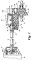
- Fig.3 shows the change speed transmission 28 and transfer transmission 29 in more detail.
- the change speed transmission 28 has a housing which comprises a main casing 36 and an end plate 37.
- the transfer transmission 29 includes a housing comprising a main casing 38 and the end plate 37 which it shares with the change speed transmission 28.
- Rotating components of the change speed transmission 28 include a input shaft 39 and an output shaft 41 both journalled in the main casing 36 of the change speed transmission and in the end plate 37.
- the input shaft 39 and the output shaft 41 are axially offset, i.e.
- the output shaft 41 drives a lubricating oil pump 50.
- the change speed transmission 28 includes first, second, third, fourth and fifth forward ratio constant mesh gear trains 42, 23, 44, 45 and 46 respectively, each gear train comprising a pair of gears, one gear of each pair being fixed to or integral with the input shaft 39 and the other of each pair being mounted on the output shaft 41 for selection by synchromesh clutches.
- a conventional selector mechanism (not shown) is used to select the gears and a reverse gear train 47 is engaged by moving a reverse idler gear (not shown) into mesh.
- the output shaft 41 acts as an input shaft for the transfer transmission 29, the driving gears of two pairs of output gear trains 53, 54 being mounted on the output shaft 41 and selectable by a synchromesh mechanism 55 to give a high range output (gear train 53) or a low range output (gear train 54).
- the driven gears of the gear trains 53 and 54 form part of an input member of a centre differential 56.
- the differential may be of a limited slip type, e.g. a Torsen (Trade Mark).
- the outputs of the centre differential 56 are connected to flanged stub shafts 57 and 58 which are connected to the front propshaft 34 and the rear propshaft 35 respectively.
- the stub shafts 57, 58 are axially offset from the input shaft 39 and the output shaft 41.
- the front and rear propshafts 34, 45 are of substantially equal length which will help to reduce any vibration and harshness caused or exacerbated by the use of excessively short propshafts and increases the service life of the associated universal joints.
- the transfer transmission 29 substantially midway between the axles 16 and 18, the polar moment of inertia of the vehicle is reduced and the various components of the transmission can be packaged to provide good ground clearance without undue difficulty.
- a tunnel 60 formed in a floor 61 of the vehicle will be positioned well forward of a rear passenger foot well 62 and will not intrude into a front passenger foot well 63. That feature is particularly advantageous from the point of view of passenger leg room and comfort.
- a catalytic converter can be positioned close to the engine 26 i.e. with only a short intermediate length of pipe, so that it can reach its operational temperature much sooner that if it is positioned further from the engine.
- mountings for the engine 26 are required to absorb engine torque only.
- the bell housing 27 and the casing of the change speed transmission 28 are connected by a tubular housing which surrounds the input propshaft and which eliminates the need for universal joints.
- the change speed transmission 28 and the transfer transmission 29 are integrated to a large extent and, in the arrangement shown in Fig.3, use a common lubricating oil system.
- the main casing 36, the input shaft 39 and all the gear wheels and parts of the synchromesh mechanism associated with the gear trains 42, 43, 44, 45, 46 and 47 are all common to or substantially identical to corresponding parts of a "parent" transmission produced for a front wheel drive motor vehicle having an engine mounted transversely in the vehicle, the output shaft in the parent transmission normally driving a differential connected to output shafts which drive the front wheels.
- the parent change speed transmission is, however, modified so that the input shaft 39 extends from the opposite end for which it was designed so that the transfer transmission 29 and the input shaft 39 will be arranged at opposite ends of the change speed transmission.
- the modification does not involve any changes to the gear trains and synchromesh mechanisms.
- a transmission assembly comprising the change speed transmission 28 and the transfer transmission 29 can be considerably more compact than a comparable assembly of a conventional longitudinal engine 4x4 drive train where the output from the change speed transmission is axially in line with the input, this is largely achieved by the differential output shafts 57, 58 and the change speed transmission output shaft being axially offset from the input shaft 39, allowing the input gears of the transfer transmission gear trains 53, 54 to be axially offset from the input shaft 39. Further space saving is achieved by having the fixed gears of the gear trains 42, 43, 44, 45 and 46 on the input shaft 39, these generally being smaller than the gears on the output shaft which have to accommodate the synchromesh clutches.
- the change speed transmission could comprise an automatic transmission and the input propshaft 31 could, in such a case, transmit drive from a torque converter mounted on the engine 26.
- the transfer transmission 39 shown is of a two speed ratio High/Low range-change type, the invention may be used with a single speed ratio transfer transmission.
- the vehicle shown in Fig.1 has a chassis 21 around which a body of the vehicle is built.
- the vehicle may instead be of monocoque construction.
Landscapes
- Engineering & Computer Science (AREA)
- Chemical & Material Sciences (AREA)
- Combustion & Propulsion (AREA)
- Transportation (AREA)
- Mechanical Engineering (AREA)
- Arrangement And Driving Of Transmission Devices (AREA)
- Reciprocating, Oscillating Or Vibrating Motors (AREA)
- General Details Of Gearings (AREA)
- Lock And Its Accessories (AREA)
- Arrangement Or Mounting Of Propulsion Units For Vehicles (AREA)
- Control Of Motors That Do Not Use Commutators (AREA)
Abstract
Description
Claims (15)
- A power train for a motor vehicle having a pair of front wheels (12, 13) and a pair of rear wheels (14, 15), the power train comprising an engine (26) which, in use, is mounted longitudinally in the vehicle, a change speed transmission (28) drivably connected to the engine, a front differential (17) disposed, in use, between the front wheels and drivably connected thereto, a rear differential (19) disposed, in use, between the rear wheels and drivably connected thereto and a transfer transmission (29) mounted on the change speed transmission and drivably connected to the front differential through a front propshaft (34) and to the rear differential through a rear propshaft (35), the change speed transmission having an input shaft (39) arranged to receive drive from the engine at one end of the change speed transmission and an output shaft (41) axially offset from the input shaft and having a drive output at the opposite end of the change speed transmission, the transfer transmission being arranged at said opposite end of the change speed transmission for receiving the drive output therefrom and including a centre differential (56) having differential output shafts (57, 58) drivably connected to the front and rear propshafts and axially offset from the input shaft and from the change speed transmission output shaft, characterised in that the engine (26) is, in use, mounted adjacent one end of the vehicle and that the change speed transmission (28) is spaced from and drivably connected to the engine by an input propshaft (31).
- A power train according to Claim 1 in which the change speed transmission (28) includes constant mesh gear trains (42, 43, 44 45 and 46) each comprising a pair of gears, one gear of each pair being mounted on the input shaft (39) and the other of each pair being mounted on the output shaft (41).
- A power train according to any preceding claim in which the transfer transmission (29) includes constant mesh gear trains (53 and 54) each comprising a pair of gears, one gear of each pair being mounted on the output shaft (41) and the other of each pair being mounted on the centre differential (56).
- A power train according to any preceding claim in which the change speed transmission (28) includes a casing (36), rotary drive components (42, 43, 44, 45, 46 and 47) and selector components substantially identical to those produced for a change speed transmission used in a front wheel drive motor vehicle where the change speed transmission has a drive input shaft and a drive output shaft extending from the same end of the change speed transmission, the change speed transmission having been modified to position the drive input shaft at the opposite end to the drive output shaft for receiving drive from the input propshaft.
- A power train according to any preceding claim in which the change speed transmission (28) and the transfer transmission (29) are integrated and share common components (37, 41).
- A power train according to any any preceding claim in which a bell housing (27) on the engine (26) and a casing of the change speed transmission (28) are connected by a tubular housing which surrounds the input propshaft (31).
- A power train according to any preceding claim wherein the input propshaft (31) has a universal joint (32) at each end.
- A power train according to any preceding claim in which the transfer transmission (29) is in use mounted substantially midway between the front and rear differentials.
- A motor vehicle incorporating a power train according to any preceding claim.
- A motor vehicle according to claim 9 in which the change speed transmission is housed partly within a tunnel (60) which projects upwardly into the interior of the vehicle between footwells (62, 63) for front and rear passengers so as not to intrude into either footwell.
- A power train according to Claim 2 in which said one gear of each pair is fixed to or integral with the input shaft (39) and the other gear of each pair is selectably connected to the output shaft (41).
- A power train according to Claim 3 in which said one gear of each pair is fixed to or integral with the centre differential (56) and the other gear of each pair is selectably connected to the output shaft (41).
- A power train according to any of claims 1 to 8 or 11 or 12 in which a drive coupling (27B) is mounted on the engine (26) and the input propshaft (31) is interposed between the drive coupling and the input shaft (39) of the change speed transmission (28).
- A power train according to any of claims 1 to 8 or 11 to 13 in which the change speed transmission (28) and the transfer transmission (29) are mounted independently of the engine (26).
- A power train according to any of claims 1 to 8 or 11 to 14 in which the front and rear propshafts (34, 35) are of substantially equal length.
Applications Claiming Priority (3)
| Application Number | Priority Date | Filing Date | Title |
|---|---|---|---|
| GB9611819 | 1996-06-06 | ||
| GBGB9611819.5A GB9611819D0 (en) | 1996-06-06 | 1996-06-06 | A power train for a motor vehicle |
| PCT/GB1997/001516 WO1997046407A1 (en) | 1996-06-06 | 1997-06-05 | Motor vehicle power train |
Publications (2)
| Publication Number | Publication Date |
|---|---|
| EP0901423A1 EP0901423A1 (en) | 1999-03-17 |
| EP0901423B1 true EP0901423B1 (en) | 2000-05-17 |
Family
ID=10794831
Family Applications (1)
| Application Number | Title | Priority Date | Filing Date |
|---|---|---|---|
| EP97926093A Expired - Lifetime EP0901423B1 (en) | 1996-06-06 | 1997-06-05 | Motor vehicle power train |
Country Status (6)
| Country | Link |
|---|---|
| US (1) | US6250411B1 (en) |
| EP (1) | EP0901423B1 (en) |
| AT (1) | ATE192977T1 (en) |
| DE (1) | DE69702057T2 (en) |
| GB (1) | GB9611819D0 (en) |
| WO (1) | WO1997046407A1 (en) |
Cited By (2)
| Publication number | Priority date | Publication date | Assignee | Title |
|---|---|---|---|---|
| DE10143886C1 (en) * | 2001-09-07 | 2002-12-12 | Bayerische Motoren Werke Ag | Power take-off gear for vehicles has a pinion gear with hollow cylindrical recesses in which bearings are arranged |
| DE102004053121A1 (en) * | 2004-11-03 | 2006-05-04 | Iglhaut Gmbh | Two-wheel driven motor vehicle e.g. passenger car, has four-wheel drive with transfer gear-box having open flange bearing, at its front sides, which is covered by locking unit e.g. locking plate, over outer contour of housing of box |
Families Citing this family (14)
| Publication number | Priority date | Publication date | Assignee | Title |
|---|---|---|---|---|
| GB9518056D0 (en) * | 1995-09-05 | 1995-11-08 | Rover Group | A power train for a motor vehicle |
| US5704866A (en) * | 1996-07-26 | 1998-01-06 | New Venture Gear, Inc. | Transmission for four-wheel drive vehicles |
| DE10148088C5 (en) * | 2000-10-13 | 2019-03-07 | Schaeffler Technologies AG & Co. KG | assembly unit |
| US7059440B1 (en) | 2001-09-07 | 2006-06-13 | Polaris Industries Inc. | Snowmobile |
| US6796395B1 (en) | 2001-09-07 | 2004-09-28 | Polaris Industries Inc. | Snowmobile |
| US7370550B1 (en) | 2005-08-30 | 2008-05-13 | Dymos Co., Ltd. | Power take-off unit |
| WO2014047488A1 (en) | 2012-09-20 | 2014-03-27 | Polaris Industries Inc. | Utiliy vehicle |
| US9440671B2 (en) | 2012-09-20 | 2016-09-13 | Polaris Industries Inc. | Vehicle |
| JP6509084B2 (en) * | 2015-09-14 | 2019-05-08 | ジヤトコ株式会社 | Transmission case of transmission for vehicle |
| US20170089445A1 (en) * | 2015-09-30 | 2017-03-30 | Dimitris Korres | Differential housing |
| US9878614B1 (en) | 2016-01-27 | 2018-01-30 | Textron Innovations Inc. | All-terrain vehicle |
| US10793181B2 (en) | 2018-02-13 | 2020-10-06 | Polaris Industries Inc. | All-terrain vehicle |
| CN108468775B (en) * | 2018-05-18 | 2024-03-26 | 湖南农业大学 | Differential type four-wheel drive transmission of articulated vehicle |
| CN117320906A (en) * | 2021-05-20 | 2023-12-29 | 采埃孚股份公司 | Drive device for motor vehicle drive system of electric vehicle |
Family Cites Families (12)
| Publication number | Priority date | Publication date | Assignee | Title |
|---|---|---|---|---|
| GB453838A (en) | 1934-03-15 | 1936-09-15 | Daimler Benz Ag | Improvements in and relating to motor vehicles |
| GB476619A (en) | 1936-02-29 | 1937-12-13 | Nydqvist & Holm Ab | Improved driving mechanism for motor vehicles |
| US2904905A (en) * | 1954-09-14 | 1959-09-22 | Gen Motors Corp | All wheel drive scraper |
| US3073405A (en) * | 1960-05-25 | 1963-01-15 | Ferguson Res Ltd Harry | Vehicle braking control |
| US4381828A (en) | 1980-11-13 | 1983-05-03 | American Motors Corporation | Vehicle drive system having first and second operating modes and method of operating same |
| JPS59154427U (en) * | 1983-04-01 | 1984-10-17 | 日産自動車株式会社 | 4 wheel drive vehicle |
| JPS6076422A (en) * | 1983-09-30 | 1985-04-30 | Iseki & Co Ltd | Tractor transmission mechanism |
| US4805720A (en) | 1986-02-27 | 1989-02-21 | Clenet Alain J M | Vehicle drivetrain |
| DE3840004A1 (en) * | 1988-11-26 | 1990-05-31 | Daimler Benz Ag | MOTOR VEHICLE WITH OVER DIFFERENTIAL GEARBOX OD. DGL. DRIVED WHEELS |
| AT395566B (en) * | 1988-12-21 | 1993-01-25 | Steyr Daimler Puch Ag | MOTOR VEHICLE WITH A MULTI-STAGE MANUAL GEARBOX AND TWO DRIVEN AXLES |
| JPH0419233A (en) * | 1990-05-10 | 1992-01-23 | Nissan Motor Co Ltd | Lubricating structure for vehicular power transmission device |
| FR2695880B1 (en) | 1992-09-18 | 1994-10-21 | Renault | Propulsion and longitudinal transmission assembly for four-wheel drive vehicle. |
-
1996
- 1996-06-06 GB GBGB9611819.5A patent/GB9611819D0/en active Pending
-
1997
- 1997-06-05 AT AT97926093T patent/ATE192977T1/en not_active IP Right Cessation
- 1997-06-05 US US09/180,709 patent/US6250411B1/en not_active Expired - Lifetime
- 1997-06-05 EP EP97926093A patent/EP0901423B1/en not_active Expired - Lifetime
- 1997-06-05 DE DE69702057T patent/DE69702057T2/en not_active Expired - Fee Related
- 1997-06-05 WO PCT/GB1997/001516 patent/WO1997046407A1/en not_active Ceased
Cited By (5)
| Publication number | Priority date | Publication date | Assignee | Title |
|---|---|---|---|---|
| DE10143886C1 (en) * | 2001-09-07 | 2002-12-12 | Bayerische Motoren Werke Ag | Power take-off gear for vehicles has a pinion gear with hollow cylindrical recesses in which bearings are arranged |
| EP1291557A2 (en) | 2001-09-07 | 2003-03-12 | Bayerische Motoren Werke Aktiengesellschaft | Power divider for vehicles |
| US6814176B2 (en) | 2001-09-07 | 2004-11-09 | Bayerische Motoren Werke Aktiengesellschaft | Differential case for motor vehicles |
| DE102004053121A1 (en) * | 2004-11-03 | 2006-05-04 | Iglhaut Gmbh | Two-wheel driven motor vehicle e.g. passenger car, has four-wheel drive with transfer gear-box having open flange bearing, at its front sides, which is covered by locking unit e.g. locking plate, over outer contour of housing of box |
| DE102004053121B4 (en) * | 2004-11-03 | 2011-12-29 | Iglhaut Gmbh | Motor vehicle with four-wheel drive |
Also Published As
| Publication number | Publication date |
|---|---|
| US6250411B1 (en) | 2001-06-26 |
| ATE192977T1 (en) | 2000-06-15 |
| WO1997046407A1 (en) | 1997-12-11 |
| DE69702057D1 (en) | 2000-06-21 |
| EP0901423A1 (en) | 1999-03-17 |
| GB9611819D0 (en) | 1996-08-07 |
| DE69702057T2 (en) | 2000-11-09 |
Similar Documents
| Publication | Publication Date | Title |
|---|---|---|
| US6250411B1 (en) | Motor vehicle power train | |
| USRE32565E (en) | Four-wheel vehicle drive system | |
| EP0180374B1 (en) | Power transmission for four-wheel drive vehicle | |
| US4422520A (en) | Transmission apparatus for four-wheel drive motor vehicle | |
| EP0131892B1 (en) | Power transfer device for four wheel drive | |
| US4778026A (en) | Propeller shaft | |
| US5188574A (en) | Power train for automotive vehicle | |
| EP0901422B1 (en) | Motor vehicle power train | |
| US5042610A (en) | Four-wheel drive vehicle | |
| JP4533579B2 (en) | Power train | |
| US7357210B2 (en) | Vehicle power transmission system | |
| US4754659A (en) | Quill shaft input cluster gear for manual transmission | |
| EP0246926B1 (en) | Power transfer device for four-wheel drive | |
| US4450734A (en) | Transmission apparatus for a four-wheel drive motor vehicle | |
| EP0399502A1 (en) | Vehicular engine and power train mounting arrangement | |
| US6557439B2 (en) | Driving force distributing structure for four wheel drive vehicle | |
| US4915191A (en) | Transfer device for a four-wheel drive vehicle | |
| RU2043214C1 (en) | Transmission of four-wheel drive vehicle | |
| GB2304659A (en) | A power train for a four-wheel drive motor vehicle | |
| SU1585180A1 (en) | Vehicle transmission | |
| JPH03235721A (en) | Power train for four-wheel drive vehicle | |
| JPS635293B2 (en) | ||
| JPH04266531A (en) | Vehicle powertrain structure | |
| JPS6327218B2 (en) | ||
| EP1306261A1 (en) | A permanent four wheel drive motor vehicle |
Legal Events
| Date | Code | Title | Description |
|---|---|---|---|
| PUAI | Public reference made under article 153(3) epc to a published international application that has entered the european phase |
Free format text: ORIGINAL CODE: 0009012 |
|
| 17P | Request for examination filed |
Effective date: 19981208 |
|
| AK | Designated contracting states |
Kind code of ref document: A1 Designated state(s): AT DE ES FR IT |
|
| GRAG | Despatch of communication of intention to grant |
Free format text: ORIGINAL CODE: EPIDOS AGRA |
|
| 17Q | First examination report despatched |
Effective date: 19990503 |
|
| GRAG | Despatch of communication of intention to grant |
Free format text: ORIGINAL CODE: EPIDOS AGRA |
|
| GRAG | Despatch of communication of intention to grant |
Free format text: ORIGINAL CODE: EPIDOS AGRA |
|
| GRAH | Despatch of communication of intention to grant a patent |
Free format text: ORIGINAL CODE: EPIDOS IGRA |
|
| GRAG | Despatch of communication of intention to grant |
Free format text: ORIGINAL CODE: EPIDOS AGRA |
|
| GRAH | Despatch of communication of intention to grant a patent |
Free format text: ORIGINAL CODE: EPIDOS IGRA |
|
| GRAH | Despatch of communication of intention to grant a patent |
Free format text: ORIGINAL CODE: EPIDOS IGRA |
|
| GRAA | (expected) grant |
Free format text: ORIGINAL CODE: 0009210 |
|
| AK | Designated contracting states |
Kind code of ref document: B1 Designated state(s): AT DE ES FR IT |
|
| PG25 | Lapsed in a contracting state [announced via postgrant information from national office to epo] |
Ref country code: IT Free format text: LAPSE BECAUSE OF FAILURE TO SUBMIT A TRANSLATION OF THE DESCRIPTION OR TO PAY THE FEE WITHIN THE PRE;WARNING: LAPSES OF ITALIAN PATENTS WITH EFFECTIVE DATE BEFORE 2007 MAY HAVE OCCURRED AT ANY TIME BEFORE 2007. THE CORRECT EFFECTIVE DATE MAY BE DIFFERENT FROM THE ONE RECORDED.SCRIBED TIME-LIMIT Effective date: 20000517 Ref country code: ES Free format text: THE PATENT HAS BEEN ANNULLED BY A DECISION OF A NATIONAL AUTHORITY Effective date: 20000517 |
|
| REF | Corresponds to: |
Ref document number: 192977 Country of ref document: AT Date of ref document: 20000615 Kind code of ref document: T |
|
| REF | Corresponds to: |
Ref document number: 69702057 Country of ref document: DE Date of ref document: 20000621 |
|
| ET | Fr: translation filed | ||
| PLBE | No opposition filed within time limit |
Free format text: ORIGINAL CODE: 0009261 |
|
| STAA | Information on the status of an ep patent application or granted ep patent |
Free format text: STATUS: NO OPPOSITION FILED WITHIN TIME LIMIT |
|
| 26N | No opposition filed | ||
| PGFP | Annual fee paid to national office [announced via postgrant information from national office to epo] |
Ref country code: AT Payment date: 20040506 Year of fee payment: 8 |
|
| PG25 | Lapsed in a contracting state [announced via postgrant information from national office to epo] |
Ref country code: AT Free format text: LAPSE BECAUSE OF NON-PAYMENT OF DUE FEES Effective date: 20050605 |
|
| PGFP | Annual fee paid to national office [announced via postgrant information from national office to epo] |
Ref country code: FR Payment date: 20060605 Year of fee payment: 10 |
|
| PGFP | Annual fee paid to national office [announced via postgrant information from national office to epo] |
Ref country code: DE Payment date: 20060630 Year of fee payment: 10 |
|
| REG | Reference to a national code |
Ref country code: FR Ref legal event code: TP |
|
| REG | Reference to a national code |
Ref country code: FR Ref legal event code: TP |
|
| REG | Reference to a national code |
Ref country code: FR Ref legal event code: ST Effective date: 20080229 |
|
| PG25 | Lapsed in a contracting state [announced via postgrant information from national office to epo] |
Ref country code: DE Free format text: LAPSE BECAUSE OF NON-PAYMENT OF DUE FEES Effective date: 20080101 |
|
| PG25 | Lapsed in a contracting state [announced via postgrant information from national office to epo] |
Ref country code: FR Free format text: LAPSE BECAUSE OF NON-PAYMENT OF DUE FEES Effective date: 20070702 |