EP0901400B1 - Improved breathing regulator apparatus having automatic flow control - Google Patents
Improved breathing regulator apparatus having automatic flow control Download PDFInfo
- Publication number
- EP0901400B1 EP0901400B1 EP97915960A EP97915960A EP0901400B1 EP 0901400 B1 EP0901400 B1 EP 0901400B1 EP 97915960 A EP97915960 A EP 97915960A EP 97915960 A EP97915960 A EP 97915960A EP 0901400 B1 EP0901400 B1 EP 0901400B1
- Authority
- EP
- European Patent Office
- Prior art keywords
- regulator
- piston
- air
- chamber
- deflector member
- Prior art date
- Legal status (The legal status is an assumption and is not a legal conclusion. Google has not performed a legal analysis and makes no representation as to the accuracy of the status listed.)
- Expired - Lifetime
Links
Images


Classifications
-
- B—PERFORMING OPERATIONS; TRANSPORTING
- B63—SHIPS OR OTHER WATERBORNE VESSELS; RELATED EQUIPMENT
- B63C—LAUNCHING, HAULING-OUT, OR DRY-DOCKING OF VESSELS; LIFE-SAVING IN WATER; EQUIPMENT FOR DWELLING OR WORKING UNDER WATER; MEANS FOR SALVAGING OR SEARCHING FOR UNDERWATER OBJECTS
- B63C11/00—Equipment for dwelling or working underwater; Means for searching for underwater objects
- B63C11/02—Divers' equipment
- B63C11/18—Air supply
- B63C11/22—Air supply carried by diver
- B63C11/2227—Second-stage regulators
Definitions
- the present invention relates generally to pressure regulation and self-contained breathing systems such as those used in scuba diving equipment and more specifically, to a new improved means for automatically altering the breathing characteristics of a demand-type regulator by automatic adjustment of the venturi action in the regulator in accordance with depth during diving.
- Pressure regulators such as those employed in underwater breathing apparatus, utilize the pressure differential on opposite sides of a flexible diaphragm to operate an air valve which supplies air to a breathing chamber from which the diver breathes.
- a flexible diaphragm is mounted to cover an opening in the wall of the breathing chamber whereby expansion of the diaphragm actuates the air valve. More specifically, when the diver inhales while the air inlet valve is closed, the pressure in the breathing chamber is reduced causing the diaphragm to bow inwards inside the breathing chamber and thereby allowing an air inlet valve to open. When the diver exhales, pressure in the chamber increases causing the diaphragm to move out to its original condition thereby closing the air inlet valve.
- Recent prior art includes disclosure of various pressure regulator structures which provide a reduction in the effort required by the diver to breathe from such regulators. More specifically, regulators have been designed so that a portion of the inlet air travels into the breathing mouthpiece area in the form of a stream of air which produces a venturi effect. This venturi effect further reduces the pressures in the breathing chamber so that in effect the diver is not necessarily doing all the work required to sufficiently reduce the breathing chamber pressure to pull in and retain the diaphragm and cracking effort force setting whereby to open the air inlet valve. Thus. the venturi effect makes its easier for the diver to inhale air from the regulator. Breathing regulators which employ such venturi-type action to assist in responding to the breathing demand of the diver are highly advantageous. Unfortunately, they are not always optimally configured for the breathing requirements for each diver or for particular diving depths where ambient pressure increases as a function of depth thereby changing the parameters for the diver's degree of breathing difficulty and breathing requirements.
- the requirement for the second stage regulator can change. On the surface, the regulator must be stable. The second stage should not accidentally flow air without stopping on its own. Unfortunately, when a scuba regulator is tuned for stable surface operation (no venturi), the performance under deeper diving conditions can suffer. And if the regulator second stage is adjusted for deep diving, the surface performance can be too sensitive causing uncontrolled free flow of air forcing the scuba diver to manually stop the flow of air by blocking the mouthpiece exit with his finger or glove.
- Patent No. 4,214,580 to Pedersen discloses a breathing apparatus of the venturi action regulator-type hereinabove discussed which utilizes an additional moving baffle to alter the venturi effect after the diver initially inhales. While such modification to the venturi action is accomplished automatically, it does not appear to be responsive to ambient water pressure variation with depth.
- Patent No. 4,147,176 to Christianson discloses the concept of using a conical platform in conjunction with a diaphragm wherein the diaphragm gradually flattens down against the platform to reduce the effect of sensing area during the breathing cycle.
- One embodiment is disclosed which has an adjustable aspirator which permits the diver to externally change the aspiration effect during the dive.
- the diaphragm and conical platform interact to control the venturi assist during the breathing cycle which makes the performance of the regulator substantially non-uniform during the breathing cycle.
- the diver may adjust the regulator characteristics to provide him with an advantageous operation for one aspect of the breathing cycle only to find that during another portion of the breathing cycle the adjustment is unsuitable.
- U.S. Patent No. 3,526,241 to Veit is directed to an oxygen-air diluter for breathing apparatus employing an altitude controlled Venturi mixing mechanism.
- the diluter apparatus is shown in its low altitude configuration with conically shaped valve member 24 sealing conical valve seat 18.
- the diluter is shown in a high altitude configuration.
- bellows 47 has expanded due to the lower air pressure exposed through aperture 49.
- conically shaped valve member 24 is drawn away from conical valve seat 18. thereby permitting oxygen to enter Venturi throat portion 22 from inlet 12.
- U.S. Patent No. 4,796,618 to Garrafffa which contains the features of the preamble of independent claim 1, is directed to a breathing regulator apparatus having a manually adjusted Venturi valve.
- flow vane 22 is adjusted so that all or virtually all of the air stream 28 emanating from the air inlet valve 18 is directed into the mouthpiece tube 19.
- the position of flow vane 22 has the effect of splitting the air stream 28 into two components, namely, a first component 30 which is directed towards the diaphragm 16 and a second component 32 which is directed through the mouthpiece tube 19.
- U.S. Patent No. 3,308,817 to Seeler is directed to a reduction regulator valve for a scuba system having an automatic depth controlled mixing adjustment system.
- the pressure exerted by the water within the end cap 25 on the bellows 49 will contract the bellows, which in turn will permit the coil spring 57 to extend, thereby lessening the pressure on the diaphragm 54, permitting the valve 36 to close under the action of the valve spring 37.
- FIG. 7 shows a type B reducer which increases the flow of gas with increasing environmental pressure.
- This reducer comprises a body 200, a diaphragm 201 cooperating with a disk 202 which, by means of a mechanical connection member 203, cooperates with a further disk 204 associated with a diaphragm 205 which, by means of the disk 206 and the mechanical connection element 207, cooperates with a plug 208.
- blades or vanes can also be manually repositioned to allow rapid unobstructed air passa ge through the second stage causing the second stage to venturi assist (free flow).
- This venturi assist will increase the regulator performance by lowering the mechanical effort (or diver inhalation effort) required to breath the second stage.
- a disadvantage of the manual design is that the scuba regulator second stage is located in the mouth and held by the teeth by means of a rubber mouthpiece. Locating the manual switch is difficult and confusing. This adjustment is made by feel not sight when the regulator is in the mouth. These manual switches tend to be small and located in difficult locations to reach with the fingers. Also, divers that wear a thermally protecting glove cannot locate these manual switches. Sometimes the adjustment is so difficult to locate, the entire second stage must be removed from the mouth so the diver can see where the exact tuning position is with respect to incremental notching or indicator numbers. This is deemed an unsafe procedure. A better non-manual flow control is needed.
- the present invention comprises an inhalation demand breathing regulator which solves the aforementioned need. More specifically, the present invention comprises a breathing regulator in which an automatically adjustable flow deflector or flow vane is utilized to create a diversion of high velocity air to direct it at the mouthpiece area of the regulator housing whereby to provide an automatic means for increasing the vacuum assist in demand regulators. When the flow vane is withdrawn, the air stream is redirected back into the housing, thus balancing the low pressure area behind the diaphragm which prevents a free flow condition and allows the demand regulator to be less sensitive to ambient water conditions.
- the automatic flow control, or A.F.C. is used in scuba diving regulator second stages to automatically regulate the venturi or aspirated flow of air to the diver at different depths.
- A.F.C. allows the regulator second stage to be stable on the surface (no venturi) and yet provides excellent performance at depth (maximum venturi) automatically freeing the diver of making any needed manual adjustments to the second stage under water.
- the present invention does not depend upon the relative position of a diaphragm and for example, a conical platform which relationship varies non-linearly during a breathing cycle.
- the effect of the present invention is a venturi assisted demand regulator which is less complex in structure, more reliable and more predictable in performance and which varies automatically with depth increasing the venturi effect or assist level as the diver descends and reducing the venturi effect or assist level as the diver ascends.
- the improved breathing regulator apparatus 10 of the present invention comprises a demand valve 12 having an air inlet tube 13 which will be connected to a suitable source of pressurized air supply in a well-known manner.
- Apparatus 10 also comprises a diaphragm 16 cooperating with a lever 20 to selectively actuate the air inlet demand valve 12 in response to the breather's inhalation requirements.
- Lever 20 unseats a poppet 22 from an orifice 14 to open valve 12.
- Apparatus 10 also provides a mouthpiece tube 28 connected to a mouthpiece (not shown) which is normally retained within the mouth of the user permitting access to incoming air from air passage 26.
- Apparatus 10 also provides a piston-controlled deflector or flow vane 30 which comprises the critical component of the present invention as is hereinafter discussed.
- Apparatus 10 also comprises exhaust ports and an exhaust valve (not shown) which in combination, provide means for exhausting the exhalation gas of the user through the regulator 10.
- the position of diaphragm 16 is determined by the relative pressure differential on opposing sides of the diaphragm within the diaphragm cover 18 and housing 19.
- the center of the diaphragm is provided with a bearing surface which bears against the lever 20 the position of which determines whether the air inlet valve 12 is opened or closed.
- the air pressure in the interior of the regulator is reduced. This reduction in the air pressure causes the central portion of diaphragm 16 to be sucked in towards the mouthpiece tube and compresses lever 20 and opens the air inlet valve 12.
- the air inlet valve is opened, a stream of air is generated and flows through air exit 24 in the general direction of the mouthpiece tube 28 through the mouthpiece tube passage 26 thereby responding to the user's inhalation requirements, but also creating a venturi effect generated by the high velocity air emanating from the air inlet valve 12. This high velocity air pulls the still air inside the regulator along with it, causing a secondary pressure drop or a vacuum to exist inside the interior of the regulator.
- the initial inhalation effort required to open the air inlet valve 12 is commonly referred to as the cracking effort.
- the extent of inhalation effort required after the cracking effort level has been reached depends on the extent to which the level of venturi assist is utilized during the remainder of the breathing cycle.
- the user may incur a disadvantageous condition in which the air inlet valve remains open due to the venturi effect thus creating a condition of free flow which in effect forces air into the user's lungs.
- Such a condition may be desirable for the experienced diver under certain deep dive or other difficult breathing conditions.
- the less experienced diver may find such a free flow condition to be frightening or otherwise disadvantageous.
- free flow conditions occurring when the regulator is out of the mouth of the user can create a pani cky environment for the diver who feels great concern over the loss of air from his tanks.
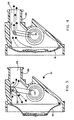
- FIGs. 1 and 2 illustrate two different automatic adjustment configurations of the flow deflector tip or vane 30 of the present invention.
- Air from the first stage is passed through an air pressure hose to the orifice 14.
- the inhalation diaphragm 16 bows inward and forces the demand lever 20 down moving the poppet 22 away from the orifice 14. Air travels past the poppet and exits from the air exit 24 and into the mouthpiece tube 28. Due to the position of the air exit, the exiting air cannot build up enough velocity to sustain a free flow venturi effect.
- the position of the deflector tip 30 is retracted in its surface resting position.
- a piston comprising piston head 33 and piston rod 32 remains static by a low ambient pressure in a pressure cavity 38 which merely balances the pressure in a sealed pressure chamber 36.
- Spring 34 assures retraction of the flow vane and the surface performance is stable due to no venturi, free flow.
- the air stream bypasses the deflector tip.
- a significant portion of the air flow from air exit 24 is redirected toward the diaphragm after deflecting off of the top portion of the mouthpiece tube 28.
- the deflector tip 30 As the diver descends under water, ambient water pressure increases in the ambient water pressure cavity 38 and presses the piston head 33 and rod 32 forward, compressing the return spring 34 and increasing the pressure in the sealed pressure chamber 36.
- the deflector tip 30 now straightens the air leaving the air exit 24 thus creating a venturi effect and increasing regulator performance. As shown in FIG. 4, at significant depths, the deflector tip 30 enters the air stream deflecting a major portion toward the mouthpiece tube 28 and through the passage 26. This deflected flow creates a vacuum assist to bow the diaphragm 16 inwardly and lower the effort required to sustain flow.
- the pressure is relieved from the ambient water pressure cavity 38 and the deflector tip 30 returns to its surface resting position and the second stage becomes stable once again.
- the O-rings 40 and 41 assure pressure integrity of chamber 36 and cavity 38 and retaining cap 42 secures return spring 34 and the piston.
- the present invention provides a novel second stage scuba diving breathing regulator having automatic flow control wherein a venturi assist effect is automatically adjusted with depth to provide no venturi effect at the surface and an increasing venturi effect as the diver descends.
- the precise location and structure of the flow control mechanism may be altered while still achieving the novel objective of automatic flow control with depth of the diver as the variable parameter.
- the deflector tip of the invention may be configured to travel in either direction with increasing depth and thus alter air flow either proportional to depth or inversely proportional to depth.
- the latter configuration can be used to increase vacuum assist with increasing depth by altering the direction of the nominal air flow to provide more deflection away from the mouthpiece tube with increasing extension of the deflector tip at shallower depths. This would constitute a reversal of the disclosed embodiment while achieving the same result. Accordingly, all such modifications are deemed to be within the scope of the invention which is to be limited only by the appended claims and their equivalents.
Description
Claims (10)
- A second stage breathing regulator (10) for divers, the regulator having a demand valve (12) to be connected to a source of pressurized air and a pressure-activated device (16, 20, 22) for opening the demand valve (12) to direct air into the regulator (10) and to a mouthpiece tube (28) to be held in the mouth by a diver, the regulator of the type wherein changes in the direction of air flow out of an air exit (24) within the regulator (10) produces a variation in venturi effect from small to large to progressively reduce the breathing effort required to keep open the demand valve (12);
a deflector member (30) located within said regulator (10) for movement relative to said air exit (24) for redirecting said air flow relative to said mouthpiece tube (28) to change said venturi effect characterised by
an ambient water pressure responsive controlling means for controlling the movement of said deflector member (30) in response to the ambient water pressure surrounding said regulator (10). - A second stage breathing regulator according to claim 1 wherein said movement controlling means comprises a piston having a piston head (33) and a piston rod (32), the piston head (33) separating two respectively isolated chambers including a first chamber (38) having ambient water pressure therein and a second chamber (36) having surface water pressure therein; the relative difference in the pressures in said first and second chambers (36, 38) determining the position of said piston.
- A second stage breathing regulator according to claim 2 wherein said deflector member (30) comprises a distal end of said piston rod (32).
- A second stage breathing regulator according to claim 2 wherein said movement controlling means further comprises a compression spring (34) located for resisting the movement of said piston rod (32) toward said air exit (24).
- A second stage breathing regulator according to claim 2 further comprising an O-ring (40) positioned annularly around said piston head (33) for isolating the first and second chambers (36, 38) from one another.
- A second stage breathing regulator according to claim 1 wherein said movement controlling means comprises a piston having a rod portion (32) and a head portion (33); the head portion (33) providing a movable sealing surface between a first chamber (38) at ambient water pressure and a second chamber (36) at a selected constant water pressure, said rod portion (32) having a distal end terminating in said deflector member (30), whereby increasing ambient water pressure forces said piston to move said deflector member (30) toward said air exit (24).
- A second stage breathing regulator according to claim 1, said regulator (10) having a first chamber (38) open to ambient water pressure and a second chamber (36) having an initially selected pressure therein, said means comprising a piston having a sealing head (33) separating said first and second chambers (36, 38) and said piston also having a rod (32) terminating in said deflector member (30), said piston being forced to move in accordance with the pressure difference between said first and second chambers (36, 38).
- A second stage breathing regulator according to claim 7 further comprises a spring (34) positioned relative to said piston rod (32) to add resistance to movement of said deflector member (30) toward said air exit (24) whereby tending to return said deflector member (30) to a stable position of minimum venturi effect.
- A second stage breathing regulator according to claim 7 further comprising at least one O-ring (40) for isolating said first chamber (38) from said second chamber (36).
- A second stage breathing regulator according to claim 7 further comprising at least one O-ring (41) for isolating said second chamber (36) from said deflector member (30).
Applications Claiming Priority (3)
| Application Number | Priority Date | Filing Date | Title |
|---|---|---|---|
| US616223 | 1996-03-15 | ||
| US08/616,223 US5678541A (en) | 1996-03-15 | 1996-03-15 | Breathing regulator apparatus having automatic flow control |
| PCT/US1997/004027 WO1997033651A1 (en) | 1996-03-15 | 1997-03-15 | Improved breathing regulator apparatus having automatic flow control |
Publications (3)
| Publication Number | Publication Date |
|---|---|
| EP0901400A1 EP0901400A1 (en) | 1999-03-17 |
| EP0901400A4 EP0901400A4 (en) | 2002-01-02 |
| EP0901400B1 true EP0901400B1 (en) | 2003-11-26 |
Family
ID=24468524
Family Applications (1)
| Application Number | Title | Priority Date | Filing Date |
|---|---|---|---|
| EP97915960A Expired - Lifetime EP0901400B1 (en) | 1996-03-15 | 1997-03-15 | Improved breathing regulator apparatus having automatic flow control |
Country Status (4)
| Country | Link |
|---|---|
| US (1) | US5678541A (en) |
| EP (1) | EP0901400B1 (en) |
| DE (1) | DE69726418T2 (en) |
| WO (1) | WO1997033651A1 (en) |
Families Citing this family (14)
| Publication number | Priority date | Publication date | Assignee | Title |
|---|---|---|---|---|
| US5690100A (en) * | 1996-08-23 | 1997-11-25 | Johnson Worldwide Assoc., Inc. | Scuba diving breathing regulator |
| US6098622A (en) * | 1998-10-15 | 2000-08-08 | Ntc Technology Inc. | Airway valve to facilitate re-breathing, method of operation, and ventilator circuit so equipped |
| USD424193S (en) * | 1998-10-15 | 2000-05-02 | Ntc Technology, Inc. | Airway valve |
| SE9902180D0 (en) * | 1999-06-10 | 1999-06-10 | Siemens Elema Ab | Apparatus for the supply of a breathing gas |
| JP3281339B2 (en) * | 1999-09-24 | 2002-05-13 | 株式会社タバタ | Diving regulator |
| JP2001088780A (en) * | 1999-09-24 | 2001-04-03 | Tabata:Kk | Regulator for diving |
| JP3317941B2 (en) * | 1999-09-24 | 2002-08-26 | 株式会社タバタ | Diving regulator |
| GB0022285D0 (en) * | 2000-09-09 | 2000-10-25 | Viamed Ltd | Breathing aid device |
| US6745770B2 (en) * | 2002-01-08 | 2004-06-08 | Resmed Limited | Flow diverter for controlling the pressure and flow rate in a CPAP device |
| US20040035415A1 (en) * | 2002-08-22 | 2004-02-26 | Michel Faligant | Breathing apparatus |
| US20060018488A1 (en) * | 2003-08-07 | 2006-01-26 | Roar Viala | Bone conduction systems and methods |
| ITGE20120027A1 (en) * | 2012-03-06 | 2013-09-07 | Mares Spa | SECOND STAGE OF PRESSURE REDUCTION FOR UNDERWATER USE PROVIDED WITH A BYPASS DUCT AND MEANS OF ADJUSTMENT OF THE GAS FLOW IN ENTRY OR OF THE PASSING FLOW TO THE INSIDE OF THAT BYPASS |
| EP2895225B1 (en) | 2012-09-14 | 2017-11-08 | Fisher & Paykel Healthcare Limited | External sensor arrangement for patient interface |
| WO2017180836A1 (en) | 2016-04-13 | 2017-10-19 | Carleton Life Support Systems, Inc. | Semi-closed circuit underwater breathing apparatus ratio regulator |
Family Cites Families (16)
| Publication number | Priority date | Publication date | Assignee | Title |
|---|---|---|---|---|
| US3308817A (en) * | 1964-04-24 | 1967-03-14 | Henry W Seeler | Reduction regulator valve for scuba system |
| US3526241A (en) * | 1967-11-24 | 1970-09-01 | Robertshaw Controls Co | Oxygen-air diluter for breathing apparatus |
| US4147176A (en) * | 1975-06-30 | 1979-04-03 | Christianson Raymond | Diaphragm assembly for the demand regulator of a breathing apparatus |
| US4214580A (en) | 1978-05-01 | 1980-07-29 | Dacor Corporation | Breathing apparatus |
| US4219017A (en) * | 1978-11-09 | 1980-08-26 | Burr John D | Pilot regulator |
| US4266538A (en) * | 1979-05-08 | 1981-05-12 | General Diving Corporation | Pressure regulator |
| US4711263A (en) * | 1985-09-18 | 1987-12-08 | Nils T. Ottestad | Double-acting valve system for underwater breathing or the like |
| US4683881A (en) * | 1985-10-30 | 1987-08-04 | U.S.D. Corp. | Breathing regulator mouthpiece |
| US4796618A (en) * | 1986-01-21 | 1989-01-10 | Undersea Industries, Inc. | Breathing regulator apparatus |
| US5251618A (en) * | 1987-09-30 | 1993-10-12 | Tony Christianson | Regulator second stage for scuba |
| US5097860A (en) * | 1991-01-04 | 1992-03-24 | Dacor Corporation | Pressure regulator for underwater breathing apparatus |
| FR2676000B1 (en) * | 1991-05-02 | 1995-12-22 | Spirotech Ind Commerc | RESPIRATORY GAS SUPPLY DEVICE. |
| US5222490A (en) * | 1991-09-26 | 1993-06-29 | Dacor Corporation | Breathing regulator having air injector feature |
| US5259375A (en) * | 1992-06-19 | 1993-11-09 | Manfred Schuler | Second stage scuba regulator with balanced piston volume control |
| EP0583531A1 (en) * | 1992-08-18 | 1994-02-23 | Claudio Beux | An improvement to automatic breathing apparatus for underwater immersion at medium and great depth |
| US5549107A (en) * | 1995-08-08 | 1996-08-27 | Under Sea Industries, Inc. | Second stage scuba diving regulator |
-
1996
- 1996-03-15 US US08/616,223 patent/US5678541A/en not_active Expired - Lifetime
-
1997
- 1997-03-15 EP EP97915960A patent/EP0901400B1/en not_active Expired - Lifetime
- 1997-03-15 DE DE69726418T patent/DE69726418T2/en not_active Expired - Fee Related
- 1997-03-15 WO PCT/US1997/004027 patent/WO1997033651A1/en active IP Right Grant
Also Published As
| Publication number | Publication date |
|---|---|
| EP0901400A4 (en) | 2002-01-02 |
| DE69726418T2 (en) | 2004-08-26 |
| EP0901400A1 (en) | 1999-03-17 |
| DE69726418D1 (en) | 2004-01-08 |
| WO1997033651A1 (en) | 1997-09-18 |
| US5678541A (en) | 1997-10-21 |
Similar Documents
| Publication | Publication Date | Title |
|---|---|---|
| EP0901400B1 (en) | Improved breathing regulator apparatus having automatic flow control | |
| US4796618A (en) | Breathing regulator apparatus | |
| US5042473A (en) | Demand valve for a respirator | |
| US4219017A (en) | Pilot regulator | |
| US5259375A (en) | Second stage scuba regulator with balanced piston volume control | |
| US4068657A (en) | Constant volume buoyancy compensation system | |
| US4273120A (en) | Underwater breathing apparatus | |
| US5467766A (en) | Valve for a pressure breathing system which accomplishes the Valsalva maneuver | |
| US4436090A (en) | Piston actuated, pilot valve operated breathing regulator | |
| EP0433406B1 (en) | Diving regulator demand valve | |
| EP1341582B1 (en) | Breathing apparatus | |
| EP1262402B1 (en) | A pressure regulator | |
| US4045835A (en) | Power deflator mechanism for scuba buoyancy vests | |
| SE501097C2 (en) | Pneumatic control valve | |
| US4214580A (en) | Breathing apparatus | |
| US3866253A (en) | Divers buoyancy vest | |
| US4137912A (en) | Diving apparatus | |
| US4446859A (en) | Breathing apparatus | |
| US4289126A (en) | Pressure regulator for breathing apparatus | |
| US4211220A (en) | Diving helmet assembly | |
| US4971050A (en) | Open circuit emergency breathing apparatus and pressure demand valve therefor | |
| US5222490A (en) | Breathing regulator having air injector feature | |
| CA1090673A (en) | Breathing apparatus | |
| EP0615899A2 (en) | Scuba breathing apparatus | |
| US4182323A (en) | Breathing apparatus |
Legal Events
| Date | Code | Title | Description |
|---|---|---|---|
| PUAI | Public reference made under article 153(3) epc to a published international application that has entered the european phase |
Free format text: ORIGINAL CODE: 0009012 |
|
| 17P | Request for examination filed |
Effective date: 19990108 |
|
| AK | Designated contracting states |
Kind code of ref document: A1 Designated state(s): DE FR GB IT |
|
| RBV | Designated contracting states (corrected) |
Designated state(s): DE FR GB IT |
|
| A4 | Supplementary search report drawn up and despatched |
Effective date: 20011115 |
|
| AK | Designated contracting states |
Kind code of ref document: A4 Designated state(s): DE FR GB IT |
|
| GRAH | Despatch of communication of intention to grant a patent |
Free format text: ORIGINAL CODE: EPIDOS IGRA |
|
| GRAH | Despatch of communication of intention to grant a patent |
Free format text: ORIGINAL CODE: EPIDOS IGRA |
|
| GRAA | (expected) grant |
Free format text: ORIGINAL CODE: 0009210 |
|
| AK | Designated contracting states |
Kind code of ref document: B1 Designated state(s): DE FR GB IT |
|
| REG | Reference to a national code |
Ref country code: GB Ref legal event code: FG4D |
|
| REF | Corresponds to: |
Ref document number: 69726418 Country of ref document: DE Date of ref document: 20040108 Kind code of ref document: P |
|
| PGFP | Annual fee paid to national office [announced via postgrant information from national office to epo] |
Ref country code: GB Payment date: 20040407 Year of fee payment: 8 |
|
| PGFP | Annual fee paid to national office [announced via postgrant information from national office to epo] |
Ref country code: FR Payment date: 20040408 Year of fee payment: 8 Ref country code: DE Payment date: 20040408 Year of fee payment: 8 |
|
| ET | Fr: translation filed | ||
| PLBE | No opposition filed within time limit |
Free format text: ORIGINAL CODE: 0009261 |
|
| STAA | Information on the status of an ep patent application or granted ep patent |
Free format text: STATUS: NO OPPOSITION FILED WITHIN TIME LIMIT |
|
| 26N | No opposition filed |
Effective date: 20040827 |
|
| PG25 | Lapsed in a contracting state [announced via postgrant information from national office to epo] |
Ref country code: IT Free format text: LAPSE BECAUSE OF NON-PAYMENT OF DUE FEES Effective date: 20050315 Ref country code: GB Free format text: LAPSE BECAUSE OF NON-PAYMENT OF DUE FEES Effective date: 20050315 |
|
| PG25 | Lapsed in a contracting state [announced via postgrant information from national office to epo] |
Ref country code: DE Free format text: LAPSE BECAUSE OF NON-PAYMENT OF DUE FEES Effective date: 20051001 |
|
| GBPC | Gb: european patent ceased through non-payment of renewal fee |
Effective date: 20050315 |
|
| PG25 | Lapsed in a contracting state [announced via postgrant information from national office to epo] |
Ref country code: FR Free format text: LAPSE BECAUSE OF NON-PAYMENT OF DUE FEES Effective date: 20051130 |
|
| REG | Reference to a national code |
Ref country code: FR Ref legal event code: ST Effective date: 20051130 |