EP0901265B1 - System for deferred call answering in a telecommunications system - Google Patents
System for deferred call answering in a telecommunications system Download PDFInfo
- Publication number
- EP0901265B1 EP0901265B1 EP98306786A EP98306786A EP0901265B1 EP 0901265 B1 EP0901265 B1 EP 0901265B1 EP 98306786 A EP98306786 A EP 98306786A EP 98306786 A EP98306786 A EP 98306786A EP 0901265 B1 EP0901265 B1 EP 0901265B1
- Authority
- EP
- European Patent Office
- Prior art keywords
- call
- switching system
- incoming call
- premise equipment
- party
- Prior art date
- Legal status (The legal status is an assumption and is not a legal conclusion. Google has not performed a legal analysis and makes no representation as to the accuracy of the status listed.)
- Expired - Lifetime
Links
Images

Classifications
-
- H—ELECTRICITY
- H04—ELECTRIC COMMUNICATION TECHNIQUE
- H04M—TELEPHONIC COMMUNICATION
- H04M3/00—Automatic or semi-automatic exchanges
- H04M3/42—Systems providing special services or facilities to subscribers
-
- H—ELECTRICITY
- H04—ELECTRIC COMMUNICATION TECHNIQUE
- H04M—TELEPHONIC COMMUNICATION
- H04M3/00—Automatic or semi-automatic exchanges
- H04M3/42—Systems providing special services or facilities to subscribers
- H04M3/428—Arrangements for placing incoming calls on hold
- H04M3/4283—Call holding circuits
-
- H—ELECTRICITY
- H04—ELECTRIC COMMUNICATION TECHNIQUE
- H04M—TELEPHONIC COMMUNICATION
- H04M3/00—Automatic or semi-automatic exchanges
- H04M3/42—Systems providing special services or facilities to subscribers
- H04M3/487—Arrangements for providing information services, e.g. recorded voice services or time announcements
-
- H—ELECTRICITY
- H04—ELECTRIC COMMUNICATION TECHNIQUE
- H04M—TELEPHONIC COMMUNICATION
- H04M2242/00—Special services or facilities
- H04M2242/22—Automatic class or number identification arrangements
-
- H—ELECTRICITY
- H04—ELECTRIC COMMUNICATION TECHNIQUE
- H04M—TELEPHONIC COMMUNICATION
- H04M3/00—Automatic or semi-automatic exchanges
- H04M3/42—Systems providing special services or facilities to subscribers
- H04M3/42025—Calling or Called party identification service
- H04M3/42034—Calling party identification service
- H04M3/42042—Notifying the called party of information on the calling party
-
- H—ELECTRICITY
- H04—ELECTRIC COMMUNICATION TECHNIQUE
- H04M—TELEPHONIC COMMUNICATION
- H04M3/00—Automatic or semi-automatic exchanges
- H04M3/42—Systems providing special services or facilities to subscribers
- H04M3/42025—Calling or Called party identification service
- H04M3/42085—Called party identification service
- H04M3/42102—Making use of the called party identifier
-
- H—ELECTRICITY
- H04—ELECTRIC COMMUNICATION TECHNIQUE
- H04Q—SELECTING
- H04Q3/00—Selecting arrangements
- H04Q3/72—Finding out and indicating number of calling subscriber
Definitions
- the invention relates generally to a telecommunications networks having voice response systems such as voice mail and, more particularly, to a system for screening and deferring the answering of incoming calls.
- the typical telecommunications network consists of a switching system connected to other switching systems in the public switched telephone network where selected ones of the switching systems are connected to customer premise equipment such as telephone sets, terminals, personal computers or the like.
- customer premise equipment such as telephone sets, terminals, personal computers or the like.
- voice mail i.e. the ability for a calling party to leave a personal recorded message for a called party
- voice response unit consisting of a voice messaging platform, announcement platform and control unit.
- the switching system also may have access to an advanced intelligence platform for providing calling party identification information.
- an incoming call from a calling party to a called party generally can be treated in one of three ways.
- the called party can answer the call by going off-hook such that a connection is established between the calling and called parties.
- the call can be switched to the voice messaging platform of the voice response system allowing the calling party to leave a recorded message that can be retrieved by the called party at a later time.
- the calling party is switched to the voice response system if the called party does not go off-hook after a predetermined period (the called party can be on another line or not answering his or her telephone) or the calling party may be allowed to access the called party's voice mail by dialing a predetermined digit sequence.
- the called party could conference the calling party into an existing call by initiating the switching system's conference circuit as is well known.
- US-A-5 309 512 addresses a call waiting deluxe feature in which a call to a busy telephone is forwarded to a service node.
- the service node utilizes a call waiting-originating feature to cause the transmission of a call waiting signal to the called telephone.
- the calling party's name is obtained from a database and is spoken to the called party in response to receipt of a flash signal.
- the service node also transmits an announcement to the called party advising of options available for handling the incoming call.
- a method according to the invention is as set out in claim 1. Preferred forms are set out in the dependent claims.
- the called party can temporarily defer answering an incoming call without interrupting an existing call.
- the identification of the calling party is provided at the called party's station set.
- the called party can request that the calling party be parked and temporarily defer answering the call simply by pressing a button on the station set.
- the called party's station set sends a data message to the system's voice response unit directing the voice response to play a "please wait" message to the calling party rather than sending the calling party to the called party's voice mail.
- the voice response unit plays the "please wait" message to the calling party and sends a call park message to the switching system hosting the station set.
- the call park message directs the switching system to park the call at a specific location as is known in the art and a corresponding call park message transmits the location of the parked call to the station set.
- a message is sent from the station set to the switching system requesting that the call parked at the identified location be connected to the station set. The call can then be connected without the existing call being interrupted and the third party knowing of its existence.
- Switching system 2 capable of hosting ISDN (Integrated Services Digital Network) interfaces.
- Switching system 2 can consist of a 5ESS ® switch manufactured and sold by Lucent Technologies Inc. or any similar switch.
- Switching system 2 hosts a number of customer lines 4 that are connected to customer premise equipment 6 such as telephones, personal computers, terminals or the like.
- Customer lines 4 can support analog or digital traffic, ISDN or the like or any combination thereof.
- Switching system 2 is connected to other switching systems in the public switched telecommunications network 7 over interoffice trunks 9.
- switching system 2 can access advanced intelligent unit (AIU) 6 such as the Advanced Communications Platform (ACP) sold by Comnet International for providing caller identification information.
- AIU advanced intelligent unit
- ACP Advanced Communications Platform
- Other systems can be used to provide the caller identification information either integrated with the switching system 2 or as a separate unit as illustrated. These systems typically use the calling party's telephone number or an automatic number identifier (ANI) received from one of the switching systems in the network to query a data base and obtain pertinent calling party information that is relayed back to the switching system 2.
- ANI automatic number identifier
- Switching system 2 also accesses a voice response system 8 such as the Intuity TM voice response system manufactured and sold by Lucent Technologies Inc. over primary rate interface (PRI) 16. Other interfaces between the voice response system 8 and switching system 2 can be used such as analog voice trunks and/or lines.
- the voice response system 8 consists of a voice messaging platform 10 and an announcements platform 12 controlled by a processor based control unit 14.
- the voice response unit 8 operates as is known to provide voice announcements to callers in a wide variety of applications and to obtain and record voice messages (voice mail) via switching system 2.
- Switching system 2 is also connected to an ISDN telephone set 18 with soft displays such as a Lucent 8520 telephone set manufactured and sold by Lucent Technologies Inc.
- Telephone set 18 is connected to switching system 2 over an ISDN interface 19.
- the standard ISDN interface consists of 2 B-channels for transmitting voice and data, a D-channel for transmitting user data and status and control messages (2B + D) where each B-channel has a rate of 64 Kbps and the D-channel operates at a rate of 16 Kbps.
- User data in the form of data packets is typically transmitted over the D-channel using the standard X.25 protocol although other protocols can also be used.
- the ISDN telephone set 18 includes a "soft" visual display 20 having a plurality of user actuated buttons 22a - 22d adjacent the display.
- the display is "soft" in that the display can change such that any particular button can serve to initiate different functions based on the context of the situation.
- the telephone set 18 is processor controlled such that the display defines the function controlled by a particular button for that scenario.
- the display shows the name and telephone number for the calling party of an incoming call and lists call treatment options for controlling that call. For example, the called party can depress button 22a to answer the incoming call, button 22b to conference the incoming call with an existing call or button 22c to send the incoming called to the called party's voice mail in voice message system 8.
- the called party can depress button 22d to send an announcement to the calling party requesting that the calling party wait for the called party to answer in accordance with the system of the invention. Operation of the system of the invention will now be described with reference to FIGs. 1 and 2 .
- the party associated with telephone set 18 (the called party) is on an existing call with a third party.
- the switching system retrieves calling party information from AIU 6 or from another source and transmits the call information to telephone set 18 over the D-channel of ISDN interface 19 (block 201).
- calling party information and the context sensitive functions are displayed on soft display 22 of telephone set where each functional activity is associated with one of buttons as shown in FIG. 1 (block 202). While in a preferred embodiment calling party information is retrieved from AIU 6 and displayed at telephone set 18, it will be appreciated that the system of the invention can operate without this information.
- the system provide an identify function.
- an "identify" function would be displayed on soft display 22 in association with one of buttons 22a-22d. Depression of the associated "identify” button sends a message to voice response system 8 over the D-channel connection thereby invoking the identify functionality.
- the voice response system 8 in response to this message, makes an announcement to the calling party requesting the calling party's identity.
- the calling party speaks his or her name and the voice response system 8, using existing speech to text conversion technology, converts the spoken identity into text data. This data can then be transmitted over the D-channel connection to telephone set 18 where it is displayed to the called party.
- the called party can then make a disposition decision for the call based on the calling party's identity.
- the called party initiates the "please wait” functionality of the invention by depressing button 22d associated with this function (block 203).
- button 22d associated with this function
- a message is sent from the telephone set 18 to switching system 2 over the D-channel requesting that a D-channel connection be established between the telephone set 18 and voice response system 8 and that a "please wait” message should be announced (block 204).
- a permanent virtual circuit PVC
- the switching system 2 in response to that message, establishes a D-channel connection 20 between the telephone set 18 and voice response system 8 and forwards the call to the voice response system 8 (block 205).
- the voice response system 8 plays a "please wait” announcement for the calling party that is maintained as part of the voice response service of the announcements platform 12 associated with the called party (block 206).
- the "please wait” message can consist of a recorded personalized announcement stored and played in a manner similar to that of voice mail announcements.
- the specific message announced can be different based on the calling party number such that particular calling parties can receive messages personalized for the individual. It is contemplated that the message delivered would state "Please wait. The called party will be with you momentarily.” or a similar message.
- the voice response system 8 also instructs the switching system 2 to park the call at a particular location and informs telephone set 18 of the location at which the call is parked (block 207).
- the call park feature is provided on commercially available switches such as the 5ESS ® switching system manufactured and sold by Lucent Technologies Inc. to retrieve calls for virtual addressing where the call is retrieved using a virtual address.
- switches such as the 5ESS ® switching system manufactured and sold by Lucent Technologies Inc. to retrieve calls for virtual addressing where the call is retrieved using a virtual address.
- the calling party's call is parked at the switching system 2 and the called party remains connected to the third party.
- the third party is not informed of the incoming call from the calling party and has not been placed on "hold.”
- the telephone set When the voice response system 8 transmits the message to telephone set 18 informing it of the location of the parked call, the telephone set displays a message associated with one of the buttons (e.g. button 22d) informing the called party that the parked call can be retrieved by pressing that button (block 208).
- the called party wishes to retrieve the parked call (e.g. after the existing call with the third party is terminated)
- the called party depresses the button (block 209).
- the telephone station 18 transmits a message to switching system 2 requesting that the parked call be connected to telephone set 18 and informing the switching system 2 of the location of the parked call as provided by the voice response system (block 210).
- telephone set 18 is a processor based intelligent CPE, it maintains an internal script for all of the details of the above-described messaging. Specifically, the internal script of telephone set 18 maintains the parked call location and the messaging protocol necessary for transmitting the location and requesting connection of the parked call to the telephone set. When the called party depresses the appropriate button, this script is followed and the appropriate messages are delivered to switching system 2 over the D-channel of ISDN interface 19. The called party need only be informed via display of that information necessary to make the appropriate decisions and depress the appropriate buttons.
- the system of the invention can also be used to disconnect an incoming call. Specifically, after the identity of the calling party is displayed at telephone set 18 as previously described, depressing a "disconnect" function button transmits a disconnect message to the voice response system 8 over the D-channel connection. In response to this message, the voice response system 8 instructs switching system 2 to terminate the connection to the calling party. Because the disconnect message goes through the voice response system 8, the termination of the call can be preceded by an announcement such as "I am busy, I will call you back" or "I am not interested, Thank you.” It is contemplated that a disconnect with recorded message is particularly useful for unwanted calls such as solicitations or harassing calls.
- telephone set 18 is an ISDN interface
- ADSI Analog Display Services Interface
- the system of the invention allows a called party to defer answering a call or disconnect a call without alerting existing calls or placing existing calls on hold. This allows the called party to handle the calls more professionally and efficiently. Moreover, the existing system efficiently uses switch resources and avoids use of resource intensive transfer circuits.
Description
- The invention relates generally to a telecommunications networks having voice response systems such as voice mail and, more particularly, to a system for screening and deferring the answering of incoming calls.
- It will be understood that the typical telecommunications network consists of a switching system connected to other switching systems in the public switched telephone network where selected ones of the switching systems are connected to customer premise equipment such as telephone sets, terminals, personal computers or the like. To provide voice mail (i.e. the ability for a calling party to leave a personal recorded message for a called party) and other voice response services a switching system is typically connected to a voice response unit consisting of a voice messaging platform, announcement platform and control unit. The switching system also may have access to an advanced intelligence platform for providing calling party identification information.
- In existing systems, an incoming call from a calling party to a called party generally can be treated in one of three ways. First, the called party can answer the call by going off-hook such that a connection is established between the calling and called parties. Second, the call can be switched to the voice messaging platform of the voice response system allowing the calling party to leave a recorded message that can be retrieved by the called party at a later time. The calling party is switched to the voice response system if the called party does not go off-hook after a predetermined period (the called party can be on another line or not answering his or her telephone) or the calling party may be allowed to access the called party's voice mail by dialing a predetermined digit sequence. Third, the called party could conference the calling party into an existing call by initiating the switching system's conference circuit as is well known.
- In order to avoid "losing" the incoming call, existing prior art systems require that the called party must go off-hook and answer the incoming call before the calling party is switched to voice mail or terminates the connection by going on-hook. If the called party is currently connected to a third party, this requires that the current caller must be placed on hold before the incoming call can be handled. Thus, the third party is made aware that the called party has received another call and must be put on hold. The called party must then juggle two "live" calls. Such a scenario is frustrating for the called party and third party and is inconvenient for the calling party.
- Thus, a system that allows a called party to screen an incoming call and temporarily defer answering the incoming call without putting a currently connected party on hold and that efficiently uses network resources is desired.
-
US-A-5 309 512 addresses a call waiting deluxe feature in which a call to a busy telephone is forwarded to a service node. The service node utilizes a call waiting-originating feature to cause the transmission of a call waiting signal to the called telephone. The calling party's name is obtained from a database and is spoken to the called party in response to receipt of a flash signal. The service node also transmits an announcement to the called party advising of options available for handling the incoming call. - A method according to the invention is as set out in claim 1. Preferred forms are set out in the dependent claims.
- In the system of the invention, the called party can temporarily defer answering an incoming call without interrupting an existing call. Specifically, when a calling party makes a call, the identification of the calling party is provided at the called party's station set. The called party can request that the calling party be parked and temporarily defer answering the call simply by pressing a button on the station set. When the button is pressed, the called party's station set sends a data message to the system's voice response unit directing the voice response to play a "please wait" message to the calling party rather than sending the calling party to the called party's voice mail. The voice response unit plays the "please wait" message to the calling party and sends a call park message to the switching system hosting the station set. The call park message directs the switching system to park the call at a specific location as is known in the art and a corresponding call park message transmits the location of the parked call to the station set. When the called party desires to answer the call, a message is sent from the station set to the switching system requesting that the call parked at the identified location be connected to the station set. The call can then be connected without the existing call being interrupted and the third party knowing of its existence.
-
-
FIG. 1 is a schematic view of a telecommunications system supporting the system of the invention. -
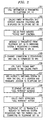
FIG. 2 is a flow chart showing the operational steps of the system of the invention. - Referring more particularly to
FIG. 1 , a telephone network in which the system of the invention can be used is illustrated including aswitching system 2 capable of hosting ISDN (Integrated Services Digital Network) interfaces.Switching system 2 can consist of a 5ESS® switch manufactured and sold by Lucent Technologies Inc. or any similar switch.Switching system 2 hosts a number of customer lines 4 that are connected tocustomer premise equipment 6 such as telephones, personal computers, terminals or the like. Customer lines 4 can support analog or digital traffic, ISDN or the like or any combination thereof.Switching system 2 is connected to other switching systems in the public switched telecommunications network 7 overinteroffice trunks 9. In a preferredembodiment switching system 2 can access advanced intelligent unit (AIU) 6 such as the Advanced Communications Platform (ACP) sold by Comnet International for providing caller identification information. Other systems can be used to provide the caller identification information either integrated with theswitching system 2 or as a separate unit as illustrated. These systems typically use the calling party's telephone number or an automatic number identifier (ANI) received from one of the switching systems in the network to query a data base and obtain pertinent calling party information that is relayed back to theswitching system 2. -
Switching system 2 also accesses avoice response system 8 such as the Intuity™ voice response system manufactured and sold by Lucent Technologies Inc. over primary rate interface (PRI) 16. Other interfaces between thevoice response system 8 andswitching system 2 can be used such as analog voice trunks and/or lines. Thevoice response system 8 consists of avoice messaging platform 10 and anannouncements platform 12 controlled by a processor basedcontrol unit 14. Thevoice response unit 8 operates as is known to provide voice announcements to callers in a wide variety of applications and to obtain and record voice messages (voice mail) viaswitching system 2. -
Switching system 2 is also connected to an ISDNtelephone set 18 with soft displays such as a Lucent 8520 telephone set manufactured and sold by Lucent Technologies Inc.Telephone set 18 is connected to switchingsystem 2 over anISDN interface 19. It will be appreciated that the standard ISDN interface consists of 2 B-channels for transmitting voice and data, a D-channel for transmitting user data and status and control messages (2B + D) where each B-channel has a rate of 64 Kbps and the D-channel operates at a rate of 16 Kbps. User data in the form of data packets is typically transmitted over the D-channel using the standard X.25 protocol although other protocols can also be used. - The ISDN
telephone set 18 includes a "soft"visual display 20 having a plurality of user actuated buttons 22a - 22d adjacent the display. The display is "soft" in that the display can change such that any particular button can serve to initiate different functions based on the context of the situation. Thetelephone set 18 is processor controlled such that the display defines the function controlled by a particular button for that scenario. The display shows the name and telephone number for the calling party of an incoming call and lists call treatment options for controlling that call. For example, the called party can depress button 22a to answer the incoming call,button 22b to conference the incoming call with an existing call or button 22c to send the incoming called to the called party's voice mail invoice message system 8. - In addition to these known operations, the called party can depress
button 22d to send an announcement to the calling party requesting that the calling party wait for the called party to answer in accordance with the system of the invention. Operation of the system of the invention will now be described with reference toFIGs. 1 and2 . For purposes of explanation assume that the party associated with telephone set 18 (the called party) is on an existing call with a third party. When another call is made to telephone 18 from a calling party (i.e.telephone 6a) the switching system retrieves calling party information from AIU 6 or from another source and transmits the call information to telephone set 18 over the D-channel of ISDN interface 19 (block 201). The calling party information and the context sensitive functions are displayed on soft display 22 of telephone set where each functional activity is associated with one of buttons as shown inFIG. 1 (block 202). While in a preferred embodiment calling party information is retrieved from AIU 6 and displayed attelephone set 18, it will be appreciated that the system of the invention can operate without this information. - If the calling party information, such as calling party name, cannot be obtained and displayed to the called party based on the AIU 6, it is contemplated that the system provide an identify function. In this scenario, an "identify" function would be displayed on soft display 22 in association with one of buttons 22a-22d. Depression of the associated "identify" button sends a message to
voice response system 8 over the D-channel connection thereby invoking the identify functionality. Specifically, thevoice response system 8, in response to this message, makes an announcement to the calling party requesting the calling party's identity. The calling party speaks his or her name and thevoice response system 8, using existing speech to text conversion technology, converts the spoken identity into text data. This data can then be transmitted over the D-channel connection to telephone set 18 where it is displayed to the called party. The called party can then make a disposition decision for the call based on the calling party's identity. - The called party initiates the "please wait" functionality of the invention by depressing
button 22d associated with this function (block 203). When the "please wait"button 22d is depressed, a message is sent from the telephone set 18 to switchingsystem 2 over the D-channel requesting that a D-channel connection be established between the telephone set 18 andvoice response system 8 and that a "please wait" message should be announced (block 204). Alternatively, a permanent virtual circuit (PVC) could carry these messages. Theswitching system 2, in response to that message, establishes a D-channel connection 20 between the telephone set 18 andvoice response system 8 and forwards the call to the voice response system 8 (block 205). It is to be understood that the capability of a switching system to forward a call from a first destination (the telephone set 18) to a second destination (the voice response system 8) is well known and is not dependent on the D-channel connection between the telephone set 18 andvoice response system 8. - The
voice response system 8 plays a "please wait" announcement for the calling party that is maintained as part of the voice response service of theannouncements platform 12 associated with the called party (block 206). In this manner the "please wait" message can consist of a recorded personalized announcement stored and played in a manner similar to that of voice mail announcements. Further, the specific message announced can be different based on the calling party number such that particular calling parties can receive messages personalized for the individual. It is contemplated that the message delivered would state "Please wait. The called party will be with you momentarily." or a similar message. Thevoice response system 8 also instructs theswitching system 2 to park the call at a particular location and informs telephone set 18 of the location at which the call is parked (block 207). It is to be understood that the call park feature is provided on commercially available switches such as the 5ESS® switching system manufactured and sold by Lucent Technologies Inc. to retrieve calls for virtual addressing where the call is retrieved using a virtual address. At this point, the calling party's call is parked at theswitching system 2 and the called party remains connected to the third party. Significantly, the third party is not informed of the incoming call from the calling party and has not been placed on "hold." - When the
voice response system 8 transmits the message to telephone set 18 informing it of the location of the parked call, the telephone set displays a message associated with one of the buttons (e.g. button 22d) informing the called party that the parked call can be retrieved by pressing that button (block 208). When the called party wishes to retrieve the parked call (e.g. after the existing call with the third party is terminated), the called party depresses the button (block 209). Thetelephone station 18 transmits a message to switchingsystem 2 requesting that the parked call be connected to telephone set 18 and informing theswitching system 2 of the location of the parked call as provided by the voice response system (block 210). Because telephone set 18 is a processor based intelligent CPE, it maintains an internal script for all of the details of the above-described messaging. Specifically, the internal script of telephone set 18 maintains the parked call location and the messaging protocol necessary for transmitting the location and requesting connection of the parked call to the telephone set. When the called party depresses the appropriate button, this script is followed and the appropriate messages are delivered to switchingsystem 2 over the D-channel ofISDN interface 19. The called party need only be informed via display of that information necessary to make the appropriate decisions and depress the appropriate buttons. - In addition to deferring answering of a call as described above, the system of the invention can also be used to disconnect an incoming call. Specifically, after the identity of the calling party is displayed at telephone set 18 as previously described, depressing a "disconnect" function button transmits a disconnect message to the
voice response system 8 over the D-channel connection. In response to this message, thevoice response system 8 instructs switchingsystem 2 to terminate the connection to the calling party. Because the disconnect message goes through thevoice response system 8, the termination of the call can be preceded by an announcement such as "I am busy, I will call you back" or "I am not interested, Thank you." It is contemplated that a disconnect with recorded message is particularly useful for unwanted calls such as solicitations or harassing calls. - While a preferred embodiment of the invention has been described where telephone set 18 is an ISDN interface, it will be understood that an analog display telephone using Analog Display Services Interface (ADSI) may also be used. If such a telephone set and interface is used, switching
system 2 is programmed to present the incoming notification display and the calling party information display on the telephone set. Using the ADSI technology the switching system must also be programmed to recognize a button press on the telephone set as a request to connect to thevoice response system 8. While the preferred embodiment discloses using a "call park" feature for holding the call, similar functionality could be achieved using the automatic call distributor (ACD) functionality "queuing to an announcement", that is currently used to perform the functionality where calls are queued waiting for an available operator and a message such as "all operators are busy, please wait and we will answer your call as soon as possible" is provided. Finally, the "please wait" functionality of the present invention can be used in conjunction with the queuing capability of the existing ACD systems. As a result, multiple calls would be queued by the calling party using the "please wait" function of the invention where the queued calls are answered in sequence. - Thus, the system of the invention allows a called party to defer answering a call or disconnect a call without alerting existing calls or placing existing calls on hold. This allows the called party to handle the calls more professionally and efficiently. Moreover, the existing system efficiently uses switch resources and avoids use of resource intensive transfer circuits. It is to be understood that the above description is only of one preferred embodiment of the invention. Numerous other arrangements may be devised by one skilled in the art without departing from the scope of the invention. The invention is thus limited only as defined in the accompanying claims.
Claims (8)
- A method for deferring the answering of an incoming call from a calling party, comprising the steps of transmitting (201) an announcement of the incoming call at a customer premise equipment (20), forwarding(205) the incoming call at a switching system (2) to a voice response system (8), and playing(206) a message to the calling party, characterized by:parking (207) said incoming call at a specific location in said switching system and transmitting said specific location to said customer premise equipment, said specific location being stored by the customer premise equipment;transmitting (209) a request over a D-channel of an ISDN interface from said customer premise equipment to retrieve said parked incoming call to the switching system, the request containing the specific location so that a third party to an existing call with the consumer premise equipment is never made aware of the transmission of the request; and,connecting(210) said incoming call to said customer premise equipment by the switching system based on the specific location received from the customer premise equipment.
- The method of claim 1, wherein the step of transmitting an announcement includes the step of transmitting over the ISDN interface.
- The method of claim 1, wherein said announcement includes calling party information.
- The method of claim 1 wherein the transmitting said specific location to said customer premise equipment is accomplished without a third party to an existing call with the consumer premise equipment being aware of the incoming call.
- The method of claim 1, wherein said step of parking said incoming call includes the steps of transmitting a request for parking the call from the voice response system to the switching system including an identification of the call park location.
- The method of claim 1, wherein the step of connecting said incoming call is performed in said switching system.
- The method of claim 1, wherein said customer premise equipment includes an ISDN telephone set.
- The method of claim 1, wherein the signal and request are sent using X.25 protocol.
Applications Claiming Priority (2)
| Application Number | Priority Date | Filing Date | Title |
|---|---|---|---|
| US08/922,856 US6028922A (en) | 1997-09-03 | 1997-09-03 | System for deferred call answering in a telecommunications system |
| US922856 | 1997-09-03 |
Publications (3)
| Publication Number | Publication Date |
|---|---|
| EP0901265A2 EP0901265A2 (en) | 1999-03-10 |
| EP0901265A3 EP0901265A3 (en) | 2003-05-07 |
| EP0901265B1 true EP0901265B1 (en) | 2008-10-08 |
Family
ID=25447658
Family Applications (1)
| Application Number | Title | Priority Date | Filing Date |
|---|---|---|---|
| EP98306786A Expired - Lifetime EP0901265B1 (en) | 1997-09-03 | 1998-08-25 | System for deferred call answering in a telecommunications system |
Country Status (6)
| Country | Link |
|---|---|
| US (1) | US6028922A (en) |
| EP (1) | EP0901265B1 (en) |
| JP (1) | JP3532419B2 (en) |
| KR (1) | KR100600904B1 (en) |
| CA (1) | CA2244781C (en) |
| DE (1) | DE69840089D1 (en) |
Families Citing this family (18)
| Publication number | Priority date | Publication date | Assignee | Title |
|---|---|---|---|---|
| US7088801B1 (en) | 1997-09-08 | 2006-08-08 | Mci, Inc. | Single telephone number access to multiple communications services |
| US6748054B1 (en) * | 1997-09-08 | 2004-06-08 | Worldcom, Inc. | Single telephone number access to multiple communications services |
| US6683942B1 (en) * | 1999-09-10 | 2004-01-27 | Comdial Corporation | Telephone switching system with data integration |
| US6714637B1 (en) * | 1999-10-19 | 2004-03-30 | Nortel Networks Limited | Customer programmable caller ID alerting indicator |
| US6728360B1 (en) * | 2000-06-30 | 2004-04-27 | Nortel Networks Limited | Call processing software, methods and equipment providing enhanced notifications |
| US6748056B1 (en) * | 2000-08-11 | 2004-06-08 | Unisys Corporation | Coordination of a telephony handset session with an e-mail session in a universal messaging system |
| DE10055632A1 (en) * | 2000-11-10 | 2002-05-23 | Beyertone Ag | Apparatus for automatically playing acoustic signals such as messages or music into a telephone network |
| US7031453B1 (en) | 2001-03-19 | 2006-04-18 | Nortel Networks Limited | Telephony ring customization |
| US7133503B2 (en) * | 2003-06-30 | 2006-11-07 | Lucent Technologies Inc. | Incoming call control by the called party |
| US6975709B2 (en) * | 2003-07-08 | 2005-12-13 | Telcordia Technologies, Inc. | Triggered playback of recorded messages to incoming telephone calls to a cellular phone |
| DE102004004588A1 (en) * | 2004-01-29 | 2005-09-08 | Infineon Technologies Ag | Flexible call handling using user-defined response voice messages involves starting transmission back to caller of response voice message stored in voice message library by user interaction on part of called party |
| US7577239B1 (en) * | 2004-05-10 | 2009-08-18 | Cisco Technology, Inc. | Tracking and controlling the impact of unwanted messages |
| US7664058B1 (en) * | 2005-02-02 | 2010-02-16 | At&T Corp. | Method and apparatus for providing spontaneous multi-way telephone conversation with inserted messaging |
| US7769156B2 (en) * | 2005-04-27 | 2010-08-03 | Cisco Technology, Inc. | System and method for providing a reverse camp-on feature in a communications environment |
| US7894597B2 (en) * | 2005-10-12 | 2011-02-22 | Cisco Technology, Inc. | Categorization of telephone calls |
| US8077841B2 (en) * | 2007-06-28 | 2011-12-13 | Embarq Holdings Company, Llc | System and method for an outbound greeting |
| US8112516B2 (en) * | 2007-08-23 | 2012-02-07 | Cisco Technology, Inc. | Selective user notification based on IP flow information |
| US20090061832A1 (en) * | 2007-08-29 | 2009-03-05 | Embarq Holdings Company, Llc | System and method for wireless call parking |
Family Cites Families (23)
| Publication number | Priority date | Publication date | Assignee | Title |
|---|---|---|---|---|
| US5375161A (en) * | 1984-09-14 | 1994-12-20 | Accessline Technologies, Inc. | Telephone control system with branch routing |
| JP2672501B2 (en) * | 1986-12-22 | 1997-11-05 | 株式会社東芝 | Busy answering telephone device |
| US4924496A (en) * | 1988-05-12 | 1990-05-08 | Romek Figa D/B/A Abraham & Sons | Automatic incoming telephone call originating number and party display system |
| US5029196A (en) * | 1988-07-11 | 1991-07-02 | Dytel Corporation | Automated call screening |
| US5007076A (en) * | 1988-08-08 | 1991-04-09 | At&T Bell Laboratories | Call announcement arrangement |
| US4893329A (en) * | 1988-09-20 | 1990-01-09 | Brien Terry D O | Call deferral system for telephones |
| JPH02256358A (en) * | 1989-03-29 | 1990-10-17 | Fujitsu Ltd | Call-waiting phone service with message transmission function during busy state |
| CA2058814C (en) * | 1991-02-27 | 1996-04-09 | David Glenn Carlson | Method and apparatus for flexible and optimal telephone call acceptance and routing |
| KR950003723B1 (en) * | 1991-12-14 | 1995-04-17 | 금성정보통신 주식회사 | Automatic switching method of pabx |
| US5311576A (en) * | 1992-01-27 | 1994-05-10 | At&T Bell Laboratories | Adjunct processor embedded in a switching system |
| US5309512A (en) * | 1992-07-29 | 1994-05-03 | At&T Bell Laboratories | Call waiting deluxe feature |
| JP2904382B2 (en) * | 1992-10-02 | 1999-06-14 | キヤノン株式会社 | Telephone equipment |
| US5436937A (en) * | 1993-02-01 | 1995-07-25 | Motorola, Inc. | Multi-mode digital phase lock loop |
| US5434906A (en) * | 1993-09-13 | 1995-07-18 | Robinson; Michael J. | Method and apparatus for processing an incoming call in a communication system |
| US5625676A (en) * | 1993-09-13 | 1997-04-29 | Active Voice Corporation | Method and apparatus for monitoring a caller's name while using a telephone |
| US5668861A (en) * | 1993-12-23 | 1997-09-16 | Gte Laboratories Incorporated | Telecommunications system with notification hold |
| US5425091A (en) * | 1994-02-28 | 1995-06-13 | U S West Technologies, Inc. | Method and system for providing an automatic customer callback service |
| US5757897A (en) * | 1994-12-07 | 1998-05-26 | Digital Techniques, Inc. | Telephone switch call control unit |
| US5724411A (en) * | 1995-03-22 | 1998-03-03 | At&T Corp. | Method for selectively alerting multiple telephones of an incoming call |
| KR970009119A (en) * | 1995-07-07 | 1997-02-24 | 김광호 | Call waiting method of extension call in key phone system |
| US5661790A (en) * | 1995-11-03 | 1997-08-26 | Ericsson, Inc. | Call back service for a regulatory restrictive area |
| KR0173970B1 (en) * | 1996-04-23 | 1999-04-01 | 유기범 | How to Handle Call Waiting System for Information Electronic Switching System |
| US5764746A (en) * | 1996-05-30 | 1998-06-09 | Ericsson, Inc. | Holding party call back subscriber feature |
-
1997
- 1997-09-03 US US08/922,856 patent/US6028922A/en not_active Expired - Lifetime
-
1998
- 1998-08-10 CA CA002244781A patent/CA2244781C/en not_active Expired - Fee Related
- 1998-08-25 EP EP98306786A patent/EP0901265B1/en not_active Expired - Lifetime
- 1998-08-25 DE DE69840089T patent/DE69840089D1/en not_active Expired - Lifetime
- 1998-09-03 JP JP24890398A patent/JP3532419B2/en not_active Expired - Fee Related
- 1998-09-03 KR KR1019980036272A patent/KR100600904B1/en not_active IP Right Cessation
Also Published As
| Publication number | Publication date |
|---|---|
| CA2244781A1 (en) | 1999-03-03 |
| JPH11168567A (en) | 1999-06-22 |
| EP0901265A2 (en) | 1999-03-10 |
| US6028922A (en) | 2000-02-22 |
| DE69840089D1 (en) | 2008-11-20 |
| EP0901265A3 (en) | 2003-05-07 |
| JP3532419B2 (en) | 2004-05-31 |
| CA2244781C (en) | 2001-09-11 |
| KR19990029493A (en) | 1999-04-26 |
| KR100600904B1 (en) | 2006-10-24 |
Similar Documents
| Publication | Publication Date | Title |
|---|---|---|
| US5894504A (en) | Advanced call waiting and messaging system | |
| EP0901265B1 (en) | System for deferred call answering in a telecommunications system | |
| AU708959B2 (en) | Method to provide voice call notification and control messaging over a data path | |
| US5875231A (en) | Telephone call on hold service for a party placed on hold by another party | |
| US6724872B1 (en) | Personalized messages over Internet call waiting | |
| EP1730941B1 (en) | Method and apparatus for subscriber control of an inbound call | |
| CA2250785C (en) | Internet on hold | |
| JP3194571B2 (en) | How to connect a telephone system caller to a called party | |
| EP0590862B1 (en) | Information display provided to calling party | |
| CA2244634C (en) | Calling party invoked held call monitoring | |
| US5809128A (en) | Method and apparatus permitting notification and control of blocked incoming calls over a data network | |
| US6456601B1 (en) | Method and system to provide telephony tones and announcements in a packetized network environment | |
| US6529737B1 (en) | Apparatus and method for sending a customized message to a telephony subscriber and establishing a direct operative connection therewith within the same telephone call | |
| US5946378A (en) | Information on hold telephony service | |
| JP3115772B2 (en) | Telephone call processing method | |
| JPH1065813A (en) | Interactive call identification | |
| JP2001521701A (en) | Network integrating computer and telephone | |
| US20010012352A1 (en) | Call management system and method using the redirecting number from an isdn setup message | |
| WO2002100119A1 (en) | Method and apparatus for setting up a connection by means of a call back function of a voice mail service and a voice mail system provided with a call back function for setting up a connection | |
| JPH06225011A (en) | Incoming call request control system for electronic exchange | |
| JPH05227296A (en) | Private branch of electronic automatic exchange | |
| KR20050012361A (en) | Method and system for providing intelligent call forwarding service in mobile network |
Legal Events
| Date | Code | Title | Description |
|---|---|---|---|
| PUAI | Public reference made under article 153(3) epc to a published international application that has entered the european phase |
Free format text: ORIGINAL CODE: 0009012 |
|
| AK | Designated contracting states |
Kind code of ref document: A2 Designated state(s): AT BE CH CY DE DK ES FI FR GB GR IE IT LI LU MC NL PT SE |
|
| AX | Request for extension of the european patent |
Free format text: AL;LT;LV;MK;RO;SI |
|
| PUAL | Search report despatched |
Free format text: ORIGINAL CODE: 0009013 |
|
| AK | Designated contracting states |
Designated state(s): AT BE CH CY DE DK ES FI FR GB GR IE IT LI LU MC NL PT SE |
|
| AX | Request for extension of the european patent |
Extension state: AL LT LV MK RO SI |
|
| RIC1 | Information provided on ipc code assigned before grant |
Ipc: 7H 04M 1/663 B Ipc: 7H 04M 1/57 B Ipc: 7H 04M 3/436 B Ipc: 7H 04M 3/428 B Ipc: 7H 04M 3/50 B Ipc: 7H 04M 3/42 A |
|
| 17P | Request for examination filed |
Effective date: 20031027 |
|
| AKX | Designation fees paid |
Designated state(s): DE FR GB |
|
| 17Q | First examination report despatched |
Effective date: 20040614 |
|
| 17Q | First examination report despatched |
Effective date: 20040614 |
|
| GRAP | Despatch of communication of intention to grant a patent |
Free format text: ORIGINAL CODE: EPIDOSNIGR1 |
|
| GRAS | Grant fee paid |
Free format text: ORIGINAL CODE: EPIDOSNIGR3 |
|
| GRAA | (expected) grant |
Free format text: ORIGINAL CODE: 0009210 |
|
| AK | Designated contracting states |
Kind code of ref document: B1 Designated state(s): DE FR GB |
|
| REG | Reference to a national code |
Ref country code: GB Ref legal event code: FG4D |
|
| REF | Corresponds to: |
Ref document number: 69840089 Country of ref document: DE Date of ref document: 20081120 Kind code of ref document: P |
|
| PLBE | No opposition filed within time limit |
Free format text: ORIGINAL CODE: 0009261 |
|
| STAA | Information on the status of an ep patent application or granted ep patent |
Free format text: STATUS: NO OPPOSITION FILED WITHIN TIME LIMIT |
|
| RAP4 | Party data changed (patent owner data changed or rights of a patent transferred) |
Owner name: LUCENT TECHNOLOGIES INC. |
|
| 26N | No opposition filed |
Effective date: 20090709 |
|
| REG | Reference to a national code |
Ref country code: GB Ref legal event code: 732E Free format text: REGISTERED BETWEEN 20131121 AND 20131127 |
|
| REG | Reference to a national code |
Ref country code: FR Ref legal event code: CD Owner name: ALCATEL-LUCENT USA INC. Effective date: 20131122 |
|
| REG | Reference to a national code |
Ref country code: FR Ref legal event code: GC Effective date: 20140410 |
|
| REG | Reference to a national code |
Ref country code: FR Ref legal event code: RG Effective date: 20141015 |
|
| REG | Reference to a national code |
Ref country code: FR Ref legal event code: PLFP Year of fee payment: 18 |
|
| PGFP | Annual fee paid to national office [announced via postgrant information from national office to epo] |
Ref country code: GB Payment date: 20150819 Year of fee payment: 18 Ref country code: DE Payment date: 20150821 Year of fee payment: 18 |
|
| PGFP | Annual fee paid to national office [announced via postgrant information from national office to epo] |
Ref country code: FR Payment date: 20150820 Year of fee payment: 18 |
|
| REG | Reference to a national code |
Ref country code: DE Ref legal event code: R119 Ref document number: 69840089 Country of ref document: DE |
|
| GBPC | Gb: european patent ceased through non-payment of renewal fee |
Effective date: 20160825 |
|
| REG | Reference to a national code |
Ref country code: FR Ref legal event code: ST Effective date: 20170428 |
|
| PG25 | Lapsed in a contracting state [announced via postgrant information from national office to epo] |
Ref country code: DE Free format text: LAPSE BECAUSE OF NON-PAYMENT OF DUE FEES Effective date: 20170301 Ref country code: GB Free format text: LAPSE BECAUSE OF NON-PAYMENT OF DUE FEES Effective date: 20160825 Ref country code: FR Free format text: LAPSE BECAUSE OF NON-PAYMENT OF DUE FEES Effective date: 20160831 |