EP0901034A2 - Optical device and electrolytic solution - Google Patents
Optical device and electrolytic solution Download PDFInfo
- Publication number
- EP0901034A2 EP0901034A2 EP98116830A EP98116830A EP0901034A2 EP 0901034 A2 EP0901034 A2 EP 0901034A2 EP 98116830 A EP98116830 A EP 98116830A EP 98116830 A EP98116830 A EP 98116830A EP 0901034 A2 EP0901034 A2 EP 0901034A2
- Authority
- EP
- European Patent Office
- Prior art keywords
- silver
- solution
- electrolytic solution
- optical device
- salt
- Prior art date
- Legal status (The legal status is an assumption and is not a legal conclusion. Google has not performed a legal analysis and makes no representation as to the accuracy of the status listed.)
- Granted
Links
Images


Classifications
-
- G—PHYSICS
- G02—OPTICS
- G02F—OPTICAL DEVICES OR ARRANGEMENTS FOR THE CONTROL OF LIGHT BY MODIFICATION OF THE OPTICAL PROPERTIES OF THE MEDIA OF THE ELEMENTS INVOLVED THEREIN; NON-LINEAR OPTICS; FREQUENCY-CHANGING OF LIGHT; OPTICAL LOGIC ELEMENTS; OPTICAL ANALOGUE/DIGITAL CONVERTERS
- G02F1/00—Devices or arrangements for the control of the intensity, colour, phase, polarisation or direction of light arriving from an independent light source, e.g. switching, gating or modulating; Non-linear optics
- G02F1/01—Devices or arrangements for the control of the intensity, colour, phase, polarisation or direction of light arriving from an independent light source, e.g. switching, gating or modulating; Non-linear optics for the control of the intensity, phase, polarisation or colour
- G02F1/15—Devices or arrangements for the control of the intensity, colour, phase, polarisation or direction of light arriving from an independent light source, e.g. switching, gating or modulating; Non-linear optics for the control of the intensity, phase, polarisation or colour based on an electrochromic effect
- G02F1/1506—Devices or arrangements for the control of the intensity, colour, phase, polarisation or direction of light arriving from an independent light source, e.g. switching, gating or modulating; Non-linear optics for the control of the intensity, phase, polarisation or colour based on an electrochromic effect caused by electrodeposition, e.g. electrolytic deposition of an inorganic material on or close to an electrode
Definitions
- the present invention relates to optical devices (for example, optical displays for numeral or letter expression or X-Y matrix expression, and optical filters for controlling light transmittance or reflectance therethrough within a visible light range (wavelength: 400 to 700 nm)), and to an electrolytic solution to be used in those devices.
- optical devices for example, optical displays for numeral or letter expression or X-Y matrix expression, and optical filters for controlling light transmittance or reflectance therethrough within a visible light range (wavelength: 400 to 700 nm)
- an electrolytic solution to be used in those devices.
- Electrochromic materials (hereinafter referred to as EC materials) have heretofore been being used in voltage-driving-type displays and employed, for example, in digital timepieces and the like.
- Electrochromic displays are of a non-light-emitting type for image expression through reflected or transmitted light, and have the advantages of giving a few fatigue feelings in long-time observation and requiring relatively low driving voltage and small electric power.
- ECD Electrochromic displays
- liquid-type ECD that comprise an EC material of organic molecules of a viologen derivative capable of reversibly producing a condition of color expression and extinction.
- transmission-type or reflection-type light modulators to be driven through deposition/dissolution of metal salts are noted, and electrochemical light modulators to be driven through deposition/dissolution of silver are being developed.
- the response speed and the light shieldability of such electrochemical light modulators could be on a intended level, but the transparent electrode (that is, working electrode) to be the substrate of those devices is easily deteriorated so that the life of the devices is short.
- ITO indium tin oxide
- the object of the invention is to provide an optical device having an electrolytic solution which does not absorb visible rays (400 to 700 nm) (accordingly, the light transmittance or reflectance can be controlled within a visible light range) and which comprises, as the electrochemical light-modulating material, a silver complex salt capable of producing nearly uniform shielding against visible rays while the device is in a condition of color expression.
- the electrodes are prevented from being in an overpotential condition to thereby realize the prolongation of the life of the device, the device can be driven with power-saving, and the device is prevented from being discolored and deteriorated while depressing the formation of side-reaction products.
- the invention also provides the electrolytic solution to be in the device.
- the present inventors have obtained a non-aqueous reversible system of a silver complex salt capable of depositing silver from the silver complex salt on electrodes and dissolving silver on the electrodes (hereinafter this cycle will be referred to as "deposition/dissolution cycle"), and have constructed a light modulator of an electrochemical material.
- a power-saving optical device capable of well controlling the light transmittance or reflectance therethrough within a visible ray range and having good reversibility and spectral characteristics, and an electrolytic solution for the device, and have completed the present invention.
- the electrodes in the optical device of the invention are damaged little and are well kept stable, and, in addition, the device is discolored and deteriorated little in cycle use.
- the invention provides an optical device comprising a solution of a silver salt such as a silver halide (e.g., AgF, AgCl, AgBr, AgI) silver thiocyanate (AgSCN) as so put between a working electrode and a counter electrode that driving control of these electrodes brings about deposition or dissolution of silver, wherein;
- a silver salt such as a silver halide (e.g., AgF, AgCl, AgBr, AgI) silver thiocyanate (AgSCN)
- the invention also provides an electrolytic solution for the device. It is known that, for example, triethanolamine has a molecular weight of 149.19.
- the transparent electrode (that is, the working electrode) to be the substrate of the devices is deteriorated in cycle use, as so mentioned hereinabove, and the life of the devices is short.
- the alkali metal halide such as LiX and others noted above, is added to the electrolytic solution to form a complex salt of a silver halide in the solution. Therefore, as compared with quaternary ammonium salts which are used in conventional electrolytic solutions for dissolving silver salts therein, the alkali metal halide used in the invention has the advantages of retarding the overpotential for deposition and dissolution of silver and prolonging the life of electrodes.
- the electrolytic solution that we investigated to attain the invention comprises a silver halide of silver iodide, silver bromide or silver chloride.
- the silver halide must be formed into a silver complex salt in the electrolytic solution to dissolve it in the solution.
- the supporting salt this is an additive which does not directly participate in the silver deposition reaction but is necessary for dissolving silver
- quaternary ammonium salts easily soluble in organic solvents have heretofore been used essentially.
- low-voltage driving of optical devices is important for prolonging the life of the electrodes constituting the devices.
- an alkali metal halide as the additive for retarding overpotential in dissolving the deposited silver film, whereby the electrodes (especially, ITO transparent electrode) are prevented from being deteriorated.
- the life test of ITO electrode which we carried out verified that the cell voltage for the electrolytic solution of the invention is lower than that for the conventional electrolytic solution (containing a quaternary ammonium salt).
- the amount of the alkali metal halide (supporting salt) to be added to the electrolytic solution is preferably from 1/2 to 5 times the concentration of the silver halide in the solution.
- the alkanolamine improves the reversible, electrochemical deposition and dissolution of silver while retarding the release of halogens in the solution to prevent the solution from being discolored.
- the amount of the alkanolamine such as triethanolamine to be added to the solution is 1.0 g/L or more, preferably larger than 2.5 g/L, and more preferably not smaller than 5 g/L.
- An addition amount of the alkanolamine of not more than 10 g/L is practically useful from the viewpoint of keeping the performance of the electrolytic solution.
- the electrolytic solution (especially of the basic composition having a triethanolamine content of 5 g/L) may further contain any other additives such as coumarin and the like so as to promote the electrochemical deposition and dissolution of silver therein.
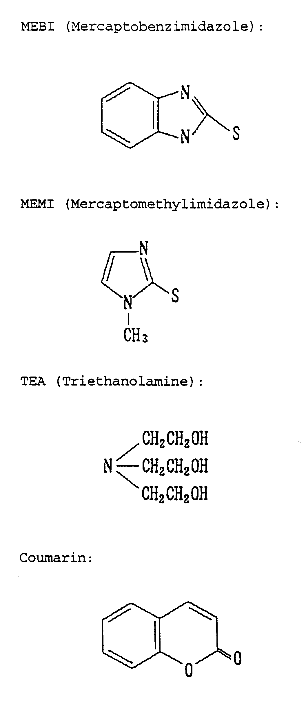
- the inventors have found that when the amount of the alkanolamine such as triethanolamine added is increased (> 5 g/L), for example, to be two times that in the basic composition, while adding a mercaptoalkylimidazole represented by the following formula: wherein R 1 , R 2 and R 3 independently represent a hydrogen atom or an alkyl group represented by the formula: C n H 2n+1 , wherein n is an integer of 0 or more, such as mercaptomethylimidazole, to the composition, then the reversibility of the electrolytic solution is much more improved, resulting in that the solution is protected from being discolored and deteriorated even though used for a long period of time at high temperatures.
- a mercaptoalkylimidazole represented by the following formula: wherein R 1 , R 2 and R 3 independently represent a hydrogen atom or an alkyl group represented by the formula: C n H 2n+1 , wherein n is an integer of 0 or more, such as
- the electrolytic solution is still good and transparent even after having been stored at 60°C for 30 days. It has been further found that, even when stored at 80°C, the electrolytic solution is less discolored and deteriorated than that to which was added any other additive (for example, mercaptobenzimidazole).
- a cyanide solution such as that used in plating bathes is known and has heretofore been used.
- cyanide solution is problematic in that safe working environments for it are difficult to ensure and that the treatment of the waste from it is troublesome. Therefore, the inventors noted non-cyanide silver salts and studied them.
- RED R ieversible E lectro D eposition
- the RED solution (electrolytic solution) that has heretofore been studied comprises silver iodide as a silver halide, ascorbic acid as a reducing agent for improving the reversibility of the solution, and dimethylsulfoxide (DMSO) as a non-aqueous solvent.
- DMSO dimethylsulfoxide
- the working environment for the devices comprising the solution is often limited. Therefore, the temperature range for the devices is broadened by using a mixed solvent in the RED solution.
- the silver halide is subjected to redox reaction shown below while in an electric field.
- the reversible system in which silver is deposited from its salt, silver halide on an electrode and is dissolved for color expression and extinction is used in the invention, which provides a power-saving, non-light-emitting optical device favorably used in a visible ray range.
- the device includes, for example, optical displays and optical filers.
- the electrolytic solution of a silver halide as dissolved in a solvent may be so filled between the working electrode and the counter electrode, at least one of which is the electrode for silver deposition and dissolution, that it is kept in contact with these electrodes.
- the silver salt such as silver halides is dissolved in water or in a non-aqueous solvent to form the electrolytic solution, which is in the device for attaining color expression and extinction through silver deposition and dissolution in the solution. More desirably, the electrolytic solution is a non-aqueous one.
- preferably used is an RED solution having a silver bromide concentration of from 0.03 to 2.0 mols/L, more preferably from 0.05 to 2.0 mols/L.
- At least one additive selected from brightening agents, complexing agents and reducing agents is preferably added to the solution.
- At least one selected from the group consisting of thiourea, 1-allyl-2-thiourea, mercaptobenzimidazole, phthalic acid, succinic acid, salicylic acid, glycolic acid, dimethylaminoborane (DMAB), trimethylaminoborane (TMAB), tartaric acid, oxalic acid and D-glucono-1,5-lactone may be used as the additive.
- the silver salt to be dissolved is preferably combined with a reducing to give a system with higher reversibility.
- Conventional RED solutions that have heretofore been studied in the art comprise ascorbic acid as the reducing agent and a non-aqueous solvent of dimethylsulfoxide (DMSO) only.
- DMSO dimethylsulfoxide
- the conventional RED solutions of that type are problematic in point of their low-temperature characteristics. For example, when used in a cold district, the solutions are often frozen. Therefore, the solvent usable in RED solutions shall be naturally limited.
- non-aqueous solvents having a low solidifying point and usable in the reversible system comprising a silver complex salt for silver deposition and dissolution on and from transparent electrodes even at low temperatures without worsening the low-temperature characteristics of the system, while investigating reducing agents applicable to the system.
- reducing agents such as DMAB, TMAB and others are satisfactorily usable in the reversible system along with the solvents which have a low solidifying point but which have not been studied at all in the art, for the purpose of improving the low-temperature characteristics of the reversible system, and that the reducing agents are more easily soluble in the solvents than in ascorbic acid noted above.
- the electrolytic solution of this type comprising the solvent having a low solidifying point solidifies at a temperature lower than that at which the conventional electrolytic solution comprising DMSO, and therefore does not freeze even when used in a cold district.
- the concentration of the reducing agent is from 1/150 to 1 time that of the silver salt.
- the solvent having a low solidifying point preferred is at least one solvent (non-aqueous solvent) selected from the group consisting of dimethylformamide (DMF), diethylformamide (DEF), N,N-dimethylacetamide (DMAA), N-methylpropionic acid amide (MPA), N-methylpyrrolidone (MP), propylene carbonate (PC), acetonitrile (AN), 2-methoxyethanol (MEOH), and also 2-ethoxyethanol (EEOH), dimethylsulfoxide (DMSO), dioxolane (DOL), ethyl acetate (EA), tetrahydrofuran (THF), methyltetrahydrofuran (MeTHF), dimethoxyethane (DME) and ⁇ -butyrolactone (GBL).
- solvent non-aqueous solvent
- DMF dimethylformamide
- DEF diethylformamide
- DMAA N,N-dimethylacetamide
- MPA N-
- non-aqueous solvents preferred are those having a lower solidifying point than DMSO (especially, the solidifying point of DMF, DEF, MEOH and EEOH is lower than that of DMSO by 70°C or more).
- the RED solution comprising a silver halide as dissolved in such a low-solidifying-point solvent has better low-temperature characteristics and are well usable even in a cold district. If DMSO is mixed with acetonitrile or the like to give a mixed solvent (for example, 1/1 by volume), the mixed solvent is usable even at low temperatures. In that manner, therefore, solvents which have good reversibility for silver deposition and dissolution but have bad temperature characteristics can be used, and the latitude for usable solvents is enlarged. Since the electrolytic solution of the invention does not freeze at low temperatures, it is well usable even in a cold district.
- the transparent electrode of the working electrode for silver deposition and dissolution may be chemically or physically modified.
- the modified transparent electrode is preferred, since the silver deposition potential for it may be lowered, and silver deposition and dissolution on and from it is easy. In this preferred embodiment, the electric damage to the transparent electrode and the electrolytic solution is reduced.
- the ITO electrode is preferably surface-treated (chemically plated) with palladium or the like in a two-liquid process using a tin solution and a palladium solution.
- the surface of the ITO electrode is activated by palladium, for which palladium nuclei are deposited on the surface of an ITO substrate. In that manner, the activity of the surface of the thus-modified ITO electrode is increased.
- the tin solution usable in this embodiment may be prepared by dissolving from 0.10 to 1.0 g of tin chloride (SnCl 2 ) in one liter of 0.010 to 0.10 % HCl; and the palladium solution may be prepared by dissolving from 0.10 to 1.0 g of palladium chloride (PdCl 2 ) in one liter of 0.010 to 0.10 % HCl.
- a metal that is more cathodic than silver or the like may be deposited on the ITO electrode through vapor deposition.
- the electrolytic solution of the invention does not absorb visible rays while the optical device comprising the solution is in color extinction condition, and that the substrate electrode for color expression and extinction (that is, the working electrode) in the device is an ITO electrode not absorbing visible rays in order to favorably drive the device.
- the RED solution system could not be stirred, since the device is very small. Therefore, it is desirable that the device is driven through current control capable of facilitating the quantitation of electrochemical silver deposition and dissolution.
- a varying current that has a rectangular profile varying from a high current value to a low current value.
- the color expression-extinction speed (silver deposition and dissolution speed) may be high.
- a varying current that has a rectangular profile varying from a low value to a high value may also be employed in the driving method.
- a constant current is also employable. In the constant-current driving method, however, it is desirable that the current is controlled with a limiter or the like at the potential at which side products will be formed (this is for keeping the electrolyte balance in the system).
- the present invention is broadly applicable to various optical devices that include, for example, displays for numeral or letter expression or for X-Y matrix expression, and optical filters for light transmittance or reflection control within a visible ray range (wavelength: 400 to 700 nm).
- the invention also provides the electrolytic solution for those optical devices, which comprises a silver halide and a supporting salt such as those noted above as dissolved in a solvent.
- the electrolytic solution comprises a silver salt such as a silver halide as dissolved in water or in a non-aqueous solvent to have a silver salt concentration of preferably from 0.03 to 2.0 mols/L, and produces color expression and extinction through silver deposition and dissolution therein.
- a silver salt such as a silver halide as dissolved in water or in a non-aqueous solvent to have a silver salt concentration of preferably from 0.03 to 2.0 mols/L, and produces color expression and extinction through silver deposition and dissolution therein.
- a supporting salt and other additives such as those noted above.
- this may contain predetermined amounts of brightening agents, complexing agents, reducing agents and other solvents.
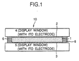
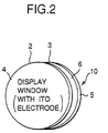
- Fig. 1 and Fig. 2 show one embodiment of the optical device 10 of the invention for an optical display (or optical filter).
- the optical device 10 illustrated comprises a pair of transparent substrates (e.g., glass substrates) 4 and 5 as spaced by a predetermined distance to be display windows constructing a cell; working electrodes (e.g., ITO electrodes) 2 and 3 formed on the inner surface of each substrate, at least one of which is a color expression electrode or a color extinction electrode; and a counter electrode 6, the electrodes being sandwiched between the substrates to face each other.
- working electrodes e.g., ITO electrodes
- those working electrodes are patterned in accordance with the object of the devices. In the drawings herein, however, the outline of the electrodes is graphically shown.
- the counter electrode 6 is provided throughout the entire circumferences of the substrates 4 and 5, and acts also as the spacer.
- used is a silver strip.
- a silver wire shall be provided as the reference electrode.
- an RED solution 1 which is prepared by dissolving RED materials of a silver halide (complex salt), an alkali metal halide, coumarin, triethanolamine, mercaptomethylimidazole and others in a non-aqueous solvent.
- the RED solution 1 is kept in contact with those electrodes in a sealed condition.
- One of the facing working electrodes 2 and 3 and the counter electrode 6 is an anode while the other is a cathode.
- a direct-current driving voltage is applied to those electrodes for a predetermined period of time to induce the redox reaction mentioned below for the silver (complex) salt on the cathode.
- the device that is originally transparent is converted into a colored one.
- the device Through the display window provided with the working electrode on which was formed the Ag precipitate, observed is a specific color of the Ag precipitate (for example, reflected color), and the device thus acts as a filter.
- the filter effect of the color expression that depends on the visible ray transmittance or reflectance through the filter (or the light and shade of the color of the filter) varies depending on the voltage applied to the filter and on the time for the voltage application. Controlling the voltage and the time makes the device function as a transmittance or reflectance-variable display or filter.
- the optical device 10 may have the working electrodes 2 and 3 on the entire inner surfaces of the cell.
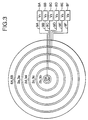
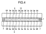
- the constitution of the cell may be, for example, as in Fig. 3 and Fig. 4.
- the working electrodes of ITO as formed on the inner surfaces of the transparent electrodes 4 and 5 are in small portions of the center electrodes 2a and 2b and the concentric ring electrodes 2b, 3b, 2c, 3c, 2d, 3d, 2e and 3e as formed around the center electrodes with being spaced to have a minor distance between the adjacent ones.
- the outermost working electrodes 2e and 3e formed is counter electrodes 6A and 6B of silver.
- Electrodes 2a, 3a, 2b, 3b, 2c, 3c, 2d, 3d, 2e, 3d, 6A and 6B are connected with driving power sources 8A, 8B, 8C, 8D, 8E and 8F, via fine wires of chromium 9A, 9B, 9C, 9D, 9E and 9F, respectively.
- the transparent electrodes 4 and 5 are spaced by the spacer 7 (in Fig. 4, the counter electrode 6 acts also as the spacer) to have a predetermined distance therebetween, and the RED solution 1 is filled and sealed in the distance.
- the RED solution 1 is controlled for the redox reaction (that is, the density) depending on the voltage applied thereto. Therefore, by varying the voltage to be applied between the electrode portions, 2a and 3a, 2b and 3b, 2c and 3c, 2d and 3d, 2e and 3e, and the electrodes 6A and 6B (referred to as V 1 , V 2 , V 3 , V 4 and V 5 , respectively), the amount of the silver precipitate to be deposited from the RED solution on each cathode portion may be varied (to the counter electrodes 6A and 6B, applied is a voltage V 6 for potential compensation).
- the RED solution 1 is entirely colored in the same color, and the density of the color may be varied uniformly depending on the voltage applied.
- the light and shade and even the gradation to be seen through the cell can be controlled in various patterns by varying the voltage to each electrode portion.
- the optical filter of this embodiment has many applications in a broad range.
- the embodiment illustrated is based on a technical idea that is quite different from that using conventional EC materials.
- used is a filter material of RED that comprises silver bromide for light modulation in optical instruments, and the color density of the RED material is varied by controlling the driving condition for the working electrode and the counter electrode (especially, by varying the voltage to be applied to those electrodes).
- the invention has realized optical displays and optical filters with color gradation.
- the invention thus provides a fine and power-saving, light-modulating device, and the capabilities of the filter comprising the device are better than those of conventional variable ND filters that are driven mechanically.
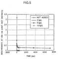
- DMSO dimethylsulfoxide
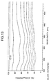
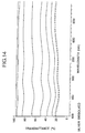
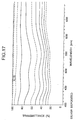
- a varying amount of TEA was added to this reference electrolytic solution.
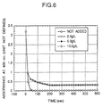
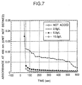
- the time-dependent absorbance at 400 nm of each of the reference electrolytic solution to which TEA was not added and the TEA-added solutions was varied under a potential condition under which the silver halide is easily oxidize at predetermined intervals.
- the data obtained are plotted in the graphs of Fig. 5, Fig. 6 and Fig. 7. In those graphs, the scales of the vertical axis and the horizontal axis are varied, but all those graphs indicate the same data relative to the varying amount of TEA added.
- a basic composition comprised of 500 mmols/L of a silver salt, AgBr, 750 mmols/L of an alkali metal halide, NaI, and, as additives, 1 g/L of coumarin and 5 g/L of triethanolamine was prepared. This was dissolved in DMSO to prepare a standard electrolytic solution.
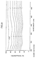
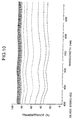
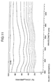
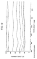
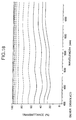
- Example 2 (Variation in transmittance in silver deposition/dissolution cycle in constant-potential method):
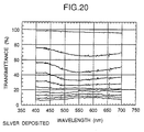
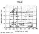
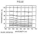
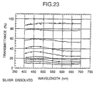
- the driving voltage in silver deposition was -1.4 V relative to silver, and the driving time was 1.0 second. Being different from this, the driving voltage in silver dissolution stepwise varied to have a driving voltage profile of +4.5 V for 20 msec ⁇ +1.6 V for 2 sec ⁇ +3.5 V for 20 msec relative to silver.
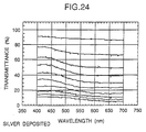
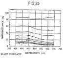
- the variation in the transmittance through each solution is shown in Fig. 9, Fig. 11, Fig. 13, Fig. 15 and Fig. 17 (in silver deposition), and in Fig. 10, Fig. 12, Fig. 14, Fig. 16 and Fig. 18 (in silver dissolution).
- the transmittance measured is based on the transmittance of the ITO electrode.
- the electrolytic solution 9 of the invention brings about satisfactory light modulation (to induce transmittance variation), as in Fig. 17 and Fig. 18. It is further known that the spectral characteristic of the silver film as deposited from this system is characterized by the uniform absorbance within a visible ray range, and that the transmittance through the solution varies in the same manner both in silver deposition and in silver dissolution. This means that the solution has a light-shielding function within a visible ray range.
- the light-modulating function of the electrolytic solution 9 does not so much differ from that of the other electrolytic solutions 5 to 8. However, even though the solution 9 contains a large amount of TEA of 10 g/L, it exhibits good light modulation. As so mentioned hereinabove, the solution 9 containing TEA has the ability to prevent it from being discolored in practical use, and is therefore advantageous.
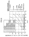
- the additives which were used herein were monoethanolamine (MEA), diethanolamine (DEA) and triethanolamine (TEA). As comparison with a system where no additive was added, the amount of each of the additives was fixed to be 2.5 g/L and 5.0 g/L, respectively. After applying an oxidation current for an arbitrary period of time, the speed of the transparentization after the application was measured at a wavelength of 400 nm. The results are shown in Fig. 19.
- the measurement of the transmittance was carried out in an interval of 0.2 second at 22°C.
- the transmittance of ITO electrodes was taken as 100%, the transmittance decreased with a lapse of time, whereas in the dissolution side, the transmittance increased (hereafter the same).
- Example 3 The same procedures as in Example 3 were repeated to prepare electrolytic solutions, except that 5 g/L of each of the additives as listed below was dissolved in each of the solvents as also listed below.
- the thus prepared electrolytic solutions were subjected to a storage test at 60°C for 30 days, and whether the color of each the solutions after the storage test was deteriorated was evaluated.
- the type of the RED material and the components constituting RED especially the type and the concentration of the supporting salt of an alkali metal halide may be varied.
- the structure comprising the ITO electrode pattern, as well as the materials for various parts constituting the cell, and even the driving method are not limited to those illustrated above.
- the electrode pattern of Fig. 17 may be varied to a linear stripe-like or cross stripe-like one; and the plural electrode portions may be in different parallel cells each filled with a different RED solution, for which, if desired, the RED solutions may be combined with any conventional EC solutions.
- the materials for the optical device of the invention may be combined with any other known filter materials (for example, organic electrochromic materials, liquid crystals, electroluminescent materials).
- the optical device of the invention has many applications, for example, as optical stops in CCD and for light modulation in various optical systems, electrophotographic duplicators and optical communication instruments.
- the technical idea on which the present invention is based is quite different from that for conventional EC materials.
- the invention is characterized in that a supporting salt such as LiX or the like, an alkanolamine and optionally mercaptomethylimidazole are added to an RED solution containing a silver halide to give a reversible system to be put between a working electrode and a counter electrode that face each other.
- driving control of those electrodes brings about silver deposition and dissolution on and from the electrodes from the reversible system.
- the present invention provides a power-saving, non-light-emitting optical device capable of being driven within a visible ray range.
- the electrodes constituting the device are prevented from being in overpotential condition, the prolongation of the device is realized and the reversibility of the electrolytic solution in the device is enhanced.
- the electrolytic solution to be in the device is protected from being discolored and deteriorated while stored at high temperatures.
Landscapes
- Physics & Mathematics (AREA)
- Nonlinear Science (AREA)
- Chemical & Material Sciences (AREA)
- Inorganic Chemistry (AREA)
- General Physics & Mathematics (AREA)
- Optics & Photonics (AREA)
- Electrochromic Elements, Electrophoresis, Or Variable Reflection Or Absorption Elements (AREA)
Abstract
Description

such as mercaptomethylimidazole, to the composition, then the reversibility of the electrolytic solution is much more improved, resulting in that the solution is protected from being discolored and deteriorated even though used for a long period of time at high temperatures.
| Basic Composition: | |
| | 500 mmols/ |
| NaI | |
| 750 mmols/L | |
| Coumarin | 1 g/L |
| Triethanolamine | 5 g/L |
| MEBI: Mercaptobenzimidazole | 1 g/L |
| MEMI: Mercaptomethylimidazole | 1 g/L |
| TEA: Triethanolamine | 5 g/L |
| | 500 mmols/ |
| NaI | |
| 750 mmols/L |
| | 500 mmols/ |
| NaI | |
| 750 mmols/L | |
| Coumarin | 1 g/L |
| MEMI | 1 g/L |
| | 500 mmols/ |
| NaI | |
| 750 mmols/L | |
| Coumarin | 1 g/L |
| MEMI | 1 g/L |
| TEA | 2.5 g/L |
| | 500 mmols/ |
| NaI | |
| 750 mmols/L | |
| Coumarin | 1 g/L |
| MEMI | 1 g/L |
| TEA | 5 g/L |
| | 500 mmols/ |
| NaI | |
| 750 mmols/L | |
| Coumarin | 1 g/L |
| MEMI | 1 g/L |
| TEA | 10 g/L |
- DMSO:
- Dimethyl sulfoxide
- DMF:
- Dimethylformamide
- DMAC:
- Dimethylacetamide
- 2-EE:
- 2-Ethoxyethanol
- NMP:
- n-Methylpyrrolidone
- GBL:
- g-Butyrolactone
- AN:
- Acetonitrile
- PC:
- Propylene carbonate
- MEA:
- Monoethanolamine
- DEA:
- Diethanolamine
- TEA:
- Triethanolamine
| [Pure solvent]
Solvent resistance of additive | |||
| Degree of deterioration in color expression | |||
| MEA | | TEA | |
| DMSO | |||
| 5 | 3 | 1 | |
| | 4 | 4 | 3 |
| | 5 | 4 | 4 |
| 2- | 2 | 2 | 1 |
| | 3 | 3 | 2 |
| | 1 | 3 | 5 |
| AN | 5 | 5 | 5 |
| | 5 | 5 | 5 |
| [Mixed solvent of DMSO with other solvent (50/50 by volume)] Solvent resistance of additive | |||
| Degree of deterioration in color expression | |||
| MEA | DEA | TEA | |
| DMSO | - | - | - |
| | 4 | 4 | 3 |
| | 4 | 4 | 4 |
| 2- | 2 | 2 | 1 |
| | 3 | 3 | 2 |
| | 1 | 3 | 4 |
| AN | 4 | 4 | 4 |
| | 4 | 4 | 4 |
Claims (26)
- An optical device comprising a silver salt solution as so put between a working electrode and a counter electrode that driving control of these electrodes brings about deposition or dissolution of silver, wherein;at least one supporting salt selected from the group consisting of LiX, NaX and KX, wherein X represents a fluorine atom, a chlorine atom, a bromine atom or an iodine atom for dissolving the silver salt in said solution, andan alkanolamine are added to said solution.
- The optical device as claimed in claim 1, wherein the alkanolamine is at least one member selected from the group consisting of triethanolamine, diethanolamine and monoethanolamine.
- The optical device as claimed in claim 1, wherein the concentration of the alkanolamine in said solution is larger than 2.5 g/L.
- The optical device as claimed in claim 1, wherein the concentration of the alkanolamine in said solution is not smaller than 5 g/L.
- The optical device as claimed in claim 1, wherein the concentration of the alkanolamine in said solution is not smaller than 5 g/L and a mercaptoalkylimidazole is further added to said solution.
- The optical device as claimed in claim 1, wherein in order to dissolve a silver halide as said silver salt, said supporting salt capable of supplying a halogen that is the same as or different from the halogen of said silver halide is added.
- The optical device as claimed in claim 1, wherein said supporting salt is added to said solution in an amount of from 1/2 to 5 times the concentration of a silver halide as said silver salt.
- The optical device as claimed in claim 1, wherein an electrolytic solution of a silver halide as said silver salt as dissolved in a solvent is so filled between said working electrode and said counter electrode, at least one of which is the electrode for deposition and dissolution of silver, that it is kept in contact with these electrodes.
- The optical device as claimed in claim 1, wherein said solution of a silver halide as said silver salt as dissolved in water or in a non-aqueous solvent is so put as to cause color expression or extinction through deposition or dissolution of silver therein.
- The optical device as claimed in claim 1, wherein said solution has a concentration of a silver halide as said silver salt of from 0.03 to 2.0 mols/L.
- The optical device as claimed in claim 9, wherein said non-aqueous solvent is at least one selected from the group consisting of dimethylformamide, diethylformamide, N,N-dimethylacetamide, N-methylpropionic acid amide, N-methylpyrrolidone, propylene carbonate, acetonitrile, 2-ethoxyethanol, 2-methoxyethanol, dimethylsulfoxide, dioxolane, ethyl acetate, tetrahydrofuran, methyltetrahydrofuran, dimethoxyethane and γ-butyrolactone.
- The optical device as claimed in claim 1, wherein said working electrode for deposition or dissolution of silver is a transparent electrode of an indium tin oxide.
- The optical device as claimed in claim 12, wherein said transparent electrode is chemically or physically modified.
- An electrolytic solution to be put between a working electrode and a counter electrode and comprising a silver salt to cause deposition or dissolution of silver through driving control of these electrodes;which contains at least one supporting salt selected from the group consisting of LiX, NaX and KX, wherein X represents a fluorine atom, a chlorine atom, a bromine atom or an iodine atom for dissolving the silver salt in the solution, andan alkanolamine both added thereto.
- The electrolytic solution as claimed in claim 14, wherein the alkanolamine is at least one member selected from the group consisting of triethanolamine, diethanolamine and monoethanolamine.
- The electrolytic solution as claimed in claim 14, wherein the concentration of the alkanolamine is larger than 2.5 g/L.
- The electrolytic solution as claimed in claim 14, wherein the concentration of the alkanolamine is not smaller than 5 g/L.
- The electrolytic solution as claimed in claim 14, in which the concentration of the alkanolamine is not smaller than 5 g/L and which further contains a mercaptoalkylimidazole.
- The electrolytic solution as claimed in claim 14, wherein in order to dissolve a silver halide as said silver salt, said supporting salt capable of supplying a halogen that is the same as or different from the halogen of said silver halide is added.
- The electrolytic solution as claimed in claim 14, wherein said supporting salt is in an amount of from 1/2 to 5 times the concentration of a silver halide as said silver salt.
- The electrolytic solution as claimed in claim 14, in which a silver halide as said silver salt is dissolved in a solvent and which is so filled between said working electrode and counter electrode, at least one of which is the electrode for deposition and dissolution of silver, that it is kept in contact with these electrodes.
- The electrolytic solution as claimed in claim 14, wherein a silver halide as said silver salt is dissolved in water or in a non-aqueous solvent to cause color expression or extinction through deposition or dissolution of silver therein.
- The electrolytic solution as claimed in claim 14, which has a concentration of a silver halide as said silver salt of from 0.03 to 2.0 mols/L.
- The electrolytic solution as claimed in claim 22, wherein said non-aqueous solvent is at least one selected from the group consisting of dimethylformamide, diethylformamide, N,N-dimethylacetamide, N-methylpropionic acid amide, N-methylpyrrolidone, propylene carbonate, acetonitrile, 2-ethoxyethanol, 2-methoxyethanol, dimethylsulfoxide, dioxolane, ethyl acetate, tetrahydrofuran, methyltetrahydrofuran, dimethoxyethane and γ-butyrolactone.
- The electrolytic solution as claimed in claim 14, for which said working electrode for deposition or dissolution of silver is a transparent electrode of an indium-tin oxide.
- The electrolytic solution as claimed in claim 25, for which said transparent electrode is chemically or physically modified.
Applications Claiming Priority (3)
| Application Number | Priority Date | Filing Date | Title |
|---|---|---|---|
| JP24264797 | 1997-09-08 | ||
| JP24264797 | 1997-09-08 | ||
| JP242647/97 | 1997-09-08 |
Publications (3)
| Publication Number | Publication Date |
|---|---|
| EP0901034A2 true EP0901034A2 (en) | 1999-03-10 |
| EP0901034A3 EP0901034A3 (en) | 1999-12-29 |
| EP0901034B1 EP0901034B1 (en) | 2003-04-09 |
Family
ID=17092163
Family Applications (1)
| Application Number | Title | Priority Date | Filing Date |
|---|---|---|---|
| EP98116830A Expired - Lifetime EP0901034B1 (en) | 1997-09-08 | 1998-09-04 | Optical device and electrolytic solution |
Country Status (4)
| Country | Link |
|---|---|
| US (1) | US6261478B1 (en) |
| EP (1) | EP0901034B1 (en) |
| KR (1) | KR100581641B1 (en) |
| DE (1) | DE69813118T2 (en) |
Cited By (6)
| Publication number | Priority date | Publication date | Assignee | Title |
|---|---|---|---|---|
| WO2003069402A1 (en) * | 2002-02-14 | 2003-08-21 | Sony Corporation | Electrochemical display element and electrochemical display |
| GB2413396A (en) * | 2004-03-26 | 2005-10-26 | Konica Minolta Holdings Inc | Display element |
| GB2413395A (en) * | 2004-03-22 | 2005-10-26 | Konica Minolta Holdings Inc | Display element |
| WO2007058046A1 (en) * | 2005-11-18 | 2007-05-24 | Konica Minolta Holdings, Inc. | Solid electrolyte and display element using the same |
| WO2010142976A1 (en) | 2009-06-08 | 2010-12-16 | Conductive Inkjet Technology Limited | Display device |
| CN115145083A (en) * | 2021-03-30 | 2022-10-04 | 北京小米移动软件有限公司 | Filters and Mobile Terminals |
Families Citing this family (4)
| Publication number | Priority date | Publication date | Assignee | Title |
|---|---|---|---|---|
| US6299741B1 (en) * | 1999-11-29 | 2001-10-09 | Applied Materials, Inc. | Advanced electrolytic polish (AEP) assisted metal wafer planarization method and apparatus |
| US20030209523A1 (en) * | 2002-05-09 | 2003-11-13 | Applied Materials, Inc. | Planarization by chemical polishing for ULSI applications |
| JP6617293B2 (en) * | 2014-08-07 | 2019-12-11 | パナソニックIpマネジメント株式会社 | Display device |
| WO2021157594A1 (en) * | 2020-02-06 | 2021-08-12 | キヤノン株式会社 | Dimming element, and optical device, imaging device, and lens unit using dimming element |
Family Cites Families (6)
| Publication number | Priority date | Publication date | Assignee | Title |
|---|---|---|---|---|
| US3961842A (en) * | 1974-09-20 | 1976-06-08 | Texas Instruments Incorporated | Regenerating electrode for electrochromic display cell |
| JP3428603B2 (en) * | 1995-03-20 | 2003-07-22 | ソニー株式会社 | Optical device and electrolyte |
| US5764401A (en) * | 1994-11-11 | 1998-06-09 | Sony Corporation | Optical apparatus |
| US5604626A (en) * | 1995-02-10 | 1997-02-18 | Donnelly Corporation | Photochromic devices |
| JPH09297324A (en) * | 1996-03-08 | 1997-11-18 | Sony Corp | Optical device and electrolyte |
| US5864420A (en) * | 1996-03-08 | 1999-01-26 | Sony Corporation | Optical unit and electrolytic solution |
-
1998
- 1998-09-04 EP EP98116830A patent/EP0901034B1/en not_active Expired - Lifetime
- 1998-09-04 DE DE69813118T patent/DE69813118T2/en not_active Expired - Lifetime
- 1998-09-04 US US09/146,961 patent/US6261478B1/en not_active Expired - Lifetime
- 1998-09-08 KR KR1019980036906A patent/KR100581641B1/en not_active Expired - Fee Related
Cited By (11)
| Publication number | Priority date | Publication date | Assignee | Title |
|---|---|---|---|---|
| WO2003069402A1 (en) * | 2002-02-14 | 2003-08-21 | Sony Corporation | Electrochemical display element and electrochemical display |
| GB2413395A (en) * | 2004-03-22 | 2005-10-26 | Konica Minolta Holdings Inc | Display element |
| US7184198B2 (en) | 2004-03-22 | 2007-02-27 | Konica Minolta Holdings, Inc. | Display element |
| GB2413395B (en) * | 2004-03-22 | 2009-09-02 | Konica Minolta Holdings Inc | Display element |
| GB2413396A (en) * | 2004-03-26 | 2005-10-26 | Konica Minolta Holdings Inc | Display element |
| US7324259B2 (en) | 2004-03-26 | 2008-01-29 | Konica Minolta Holdings, Inc. | Display element |
| GB2413396B (en) * | 2004-03-26 | 2009-08-26 | Konica Minolta Holdings Inc | Display element |
| WO2007058046A1 (en) * | 2005-11-18 | 2007-05-24 | Konica Minolta Holdings, Inc. | Solid electrolyte and display element using the same |
| WO2010142976A1 (en) | 2009-06-08 | 2010-12-16 | Conductive Inkjet Technology Limited | Display device |
| CN115145083A (en) * | 2021-03-30 | 2022-10-04 | 北京小米移动软件有限公司 | Filters and Mobile Terminals |
| CN115145083B (en) * | 2021-03-30 | 2024-04-30 | 北京小米移动软件有限公司 | Filter and mobile terminal |
Also Published As
| Publication number | Publication date |
|---|---|
| US6261478B1 (en) | 2001-07-17 |
| DE69813118T2 (en) | 2004-04-01 |
| EP0901034A3 (en) | 1999-12-29 |
| KR100581641B1 (en) | 2006-09-22 |
| DE69813118D1 (en) | 2003-05-15 |
| EP0901034B1 (en) | 2003-04-09 |
| KR19990029620A (en) | 1999-04-26 |
Similar Documents
| Publication | Publication Date | Title |
|---|---|---|
| US5880872A (en) | Optical device and electrolytic solution | |
| EP0712025B1 (en) | Optical apparatus | |
| US5864420A (en) | Optical unit and electrolytic solution | |
| JP3428603B2 (en) | Optical device and electrolyte | |
| US7046418B2 (en) | Reversible electrodeposition devices and associated electrochemical media | |
| EP1475656A1 (en) | Electrochemical display element and electrochemical display | |
| EP0901034B1 (en) | Optical device and electrolytic solution | |
| JPH11101994A (en) | Electrodeposition type image display | |
| CA2047392A1 (en) | Electrochromic compositions based on diketopyrrolopyrroles | |
| CA2199344C (en) | Optical unit electrolytic solution | |
| JP3915850B2 (en) | Optical device and electrolyte | |
| JPH11142895A (en) | Optical device and electrolyte | |
| KR100476615B1 (en) | Optical Device and Electrolytic Solution | |
| JP3446839B2 (en) | Optical filter | |
| JP3729212B2 (en) | Optical device and electrolyte | |
| JPH09297325A (en) | Optical device and electrolyte | |
| JP2005189299A (en) | Electrochemical display device | |
| US20050087448A1 (en) | Electrochemical display element and electrochemical display | |
| JP3421934B2 (en) | Optical device | |
| JPS6227115B2 (en) | ||
| JPH08136957A (en) | Optical filter | |
| JPH06301065A (en) | Optical filter | |
| JPS5936247B2 (en) | electrical display device | |
| JPH01168786A (en) | electrochromic display element |
Legal Events
| Date | Code | Title | Description |
|---|---|---|---|
| PUAI | Public reference made under article 153(3) epc to a published international application that has entered the european phase |
Free format text: ORIGINAL CODE: 0009012 |
|
| AK | Designated contracting states |
Kind code of ref document: A2 Designated state(s): DE FR GB |
|
| AX | Request for extension of the european patent |
Free format text: AL;LT;LV;MK;RO;SI |
|
| PUAL | Search report despatched |
Free format text: ORIGINAL CODE: 0009013 |
|
| AK | Designated contracting states |
Kind code of ref document: A3 Designated state(s): AT BE CH CY DE DK ES FI FR GB GR IE IT LI LU MC NL PT SE |
|
| AX | Request for extension of the european patent |
Free format text: AL;LT;LV;MK;RO;SI |
|
| 17P | Request for examination filed |
Effective date: 20000529 |
|
| AKX | Designation fees paid |
Free format text: DE FR GB |
|
| 17Q | First examination report despatched |
Effective date: 20010427 |
|
| GRAH | Despatch of communication of intention to grant a patent |
Free format text: ORIGINAL CODE: EPIDOS IGRA |
|
| GRAH | Despatch of communication of intention to grant a patent |
Free format text: ORIGINAL CODE: EPIDOS IGRA |
|
| GRAA | (expected) grant |
Free format text: ORIGINAL CODE: 0009210 |
|
| AK | Designated contracting states |
Designated state(s): DE FR GB |
|
| REG | Reference to a national code |
Ref country code: GB Ref legal event code: FG4D |
|
| ET | Fr: translation filed | ||
| PLBE | No opposition filed within time limit |
Free format text: ORIGINAL CODE: 0009261 |
|
| STAA | Information on the status of an ep patent application or granted ep patent |
Free format text: STATUS: NO OPPOSITION FILED WITHIN TIME LIMIT |
|
| 26N | No opposition filed |
Effective date: 20040112 |
|
| REG | Reference to a national code |
Ref country code: GB Ref legal event code: 746 Effective date: 20091130 |
|
| PGFP | Annual fee paid to national office [announced via postgrant information from national office to epo] |
Ref country code: GB Payment date: 20120920 Year of fee payment: 15 |
|
| PGFP | Annual fee paid to national office [announced via postgrant information from national office to epo] |
Ref country code: DE Payment date: 20120921 Year of fee payment: 15 |
|
| PGFP | Annual fee paid to national office [announced via postgrant information from national office to epo] |
Ref country code: FR Payment date: 20121010 Year of fee payment: 15 |
|
| GBPC | Gb: european patent ceased through non-payment of renewal fee |
Effective date: 20130904 |
|
| REG | Reference to a national code |
Ref country code: FR Ref legal event code: ST Effective date: 20140530 |
|
| REG | Reference to a national code |
Ref country code: DE Ref legal event code: R119 Ref document number: 69813118 Country of ref document: DE Effective date: 20140401 |
|
| PG25 | Lapsed in a contracting state [announced via postgrant information from national office to epo] |
Ref country code: GB Free format text: LAPSE BECAUSE OF NON-PAYMENT OF DUE FEES Effective date: 20130904 |
|
| PG25 | Lapsed in a contracting state [announced via postgrant information from national office to epo] |
Ref country code: FR Free format text: LAPSE BECAUSE OF NON-PAYMENT OF DUE FEES Effective date: 20130930 Ref country code: DE Free format text: LAPSE BECAUSE OF NON-PAYMENT OF DUE FEES Effective date: 20140401 |