EP0899803A1 - Elektrodengitter für Bleiakkumulatoren - Google Patents
Elektrodengitter für Bleiakkumulatoren Download PDFInfo
- Publication number
- EP0899803A1 EP0899803A1 EP98114136A EP98114136A EP0899803A1 EP 0899803 A1 EP0899803 A1 EP 0899803A1 EP 98114136 A EP98114136 A EP 98114136A EP 98114136 A EP98114136 A EP 98114136A EP 0899803 A1 EP0899803 A1 EP 0899803A1
- Authority
- EP
- European Patent Office
- Prior art keywords
- grid
- pasting
- electrode
- electrode grid
- rails
- Prior art date
- Legal status (The legal status is an assumption and is not a legal conclusion. Google has not performed a legal analysis and makes no representation as to the accuracy of the status listed.)
- Granted
Links
Images

Classifications
-
- H—ELECTRICITY
- H01—ELECTRIC ELEMENTS
- H01M—PROCESSES OR MEANS, e.g. BATTERIES, FOR THE DIRECT CONVERSION OF CHEMICAL ENERGY INTO ELECTRICAL ENERGY
- H01M4/00—Electrodes
- H01M4/02—Electrodes composed of, or comprising, active material
- H01M4/64—Carriers or collectors
- H01M4/70—Carriers or collectors characterised by shape or form
- H01M4/72—Grids
- H01M4/73—Grids for lead-acid accumulators, e.g. frame plates
-
- H—ELECTRICITY
- H01—ELECTRIC ELEMENTS
- H01M—PROCESSES OR MEANS, e.g. BATTERIES, FOR THE DIRECT CONVERSION OF CHEMICAL ENERGY INTO ELECTRICAL ENERGY
- H01M4/00—Electrodes
- H01M4/02—Electrodes composed of, or comprising, active material
- H01M4/64—Carriers or collectors
- H01M4/70—Carriers or collectors characterised by shape or form
- H01M4/72—Grids
-
- Y—GENERAL TAGGING OF NEW TECHNOLOGICAL DEVELOPMENTS; GENERAL TAGGING OF CROSS-SECTIONAL TECHNOLOGIES SPANNING OVER SEVERAL SECTIONS OF THE IPC; TECHNICAL SUBJECTS COVERED BY FORMER USPC CROSS-REFERENCE ART COLLECTIONS [XRACs] AND DIGESTS
- Y02—TECHNOLOGIES OR APPLICATIONS FOR MITIGATION OR ADAPTATION AGAINST CLIMATE CHANGE
- Y02E—REDUCTION OF GREENHOUSE GAS [GHG] EMISSIONS, RELATED TO ENERGY GENERATION, TRANSMISSION OR DISTRIBUTION
- Y02E60/00—Enabling technologies; Technologies with a potential or indirect contribution to GHG emissions mitigation
- Y02E60/10—Energy storage using batteries
-
- Y—GENERAL TAGGING OF NEW TECHNOLOGICAL DEVELOPMENTS; GENERAL TAGGING OF CROSS-SECTIONAL TECHNOLOGIES SPANNING OVER SEVERAL SECTIONS OF THE IPC; TECHNICAL SUBJECTS COVERED BY FORMER USPC CROSS-REFERENCE ART COLLECTIONS [XRACs] AND DIGESTS
- Y02—TECHNOLOGIES OR APPLICATIONS FOR MITIGATION OR ADAPTATION AGAINST CLIMATE CHANGE
- Y02P—CLIMATE CHANGE MITIGATION TECHNOLOGIES IN THE PRODUCTION OR PROCESSING OF GOODS
- Y02P70/00—Climate change mitigation technologies in the production process for final industrial or consumer products
- Y02P70/50—Manufacturing or production processes characterised by the final manufactured product
Definitions
- the invention relates to an electrode grid for lead accumulators with a rectangular grid frame, pastry rails arranged on top of it, as well as a bevy of bars, which the Form a framework for taking up the active mass.
- Electrode grids are used for the production of lead-acid batteries known, the different, sometimes contradicting requirements should do justice.
- the electrode grids are required to have a low level Weight, low internal resistance, good manufacturability, combined with a good dimensional stability with good holding capacity for the active mass.
- Lead-acid batteries used in motor vehicles are said to have a high specific Capacity both volume and weight based and have good power delivery. Since the electrode grid produced by casting processes deviations due to production have in their thickness, which leads to difficulties when pasting the active Mass leads and requires larger installation distances, was described in the document US 3,249,981 already proposed to provide pasting aid rails on the lattice frame, which then be calibrated to a uniform grid thickness. However, it will Grid weight increased again.
- the invention has for its object to provide an electrode grid that the above mentioned demands especially with regard to weight minimization.
- the object is achieved by an electrode grid, as set out in claim 1 is specified. Further advantageous configurations of the electrode grid according to the invention are set out in claims 2-4.
- Electrode plates show no deterioration compared to the known electrode plates their properties, although less lead is comparable when casting large electrode grid is used.
- Grid thicknesses 1.1, 1.3, 1.5, 1.7 and 1.9 mm this means that the corresponding grid thicknesses do not change the thickness of the grid frame is connected, but only the height of the pasting aid rails is chosen accordingly.
- a grid thickness of 1.7 mm for example achieved a weight reduction of approx. 10%.
- the Electrode grid design according to the invention improves the pastability of the electrode grid.
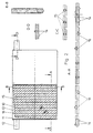
- a rectangular electrode grid 1 according to FIG. 1 has in the middle area of the upper one Frame edge 2 a current conductor flag 3.
- the grid bars 4 located in the grid frame are arranged in two groups, one group parallel to the upper frame edge 2 runs and crossed by the other group, which is aligned to the current conductor lug 3 becomes.
- the pasting aid rails 5 are on the front and rear of the upper and lower electrode grid frame and only on one side of the parallel to the upper Frame edge extending grid webs 6 arranged.
- a rectangular electrode grid 10 according to FIG. 2 has at a corner of the upper frame edge 11 a current conductor lug 12.
- the lattice frame 13 is not of uniform design, but in particular on the grid sides adjoining the current conductor lug 12 widened in the direction of the current collector lug 12.
- On the top and bottom 0.8 up to 1.2 mm thick grid frame 13 are on the front and back of the grid 10 0.2 to 0.6 mm high pasting guide rails 14 arranged, which are parallel to the upper and lower Extend lattice edge.
- the pasting aid rails 14 of the front and back of the Electrode grids 10 are offset from one another in such a way that they do not lie on one another come and would affect the stackability of the electrode grid 10.
- the diagonal lattice webs 15 have the lattice frame thickness.
- a or more of the grid webs 16 running parallel to the upper grid edge 11 also as Pastierhilschienen formed, which have an approximately triangular cross-section, wherein the base of the triangle is approximately in the middle of the grid plane and the Height of the triangle about half the grid frame thickness plus the height of the Pasting rails 14 corresponds.
- Pastierhilschienen formed, which have an approximately triangular cross-section, wherein the base of the triangle is approximately in the middle of the grid plane and the Height of the triangle about half the grid frame thickness plus the height of the Pasting rails 14 corresponds.
- Pastierhilschienen formed, which have an approximately triangular cross-section, wherein the base of the triangle is approximately in the middle of the grid plane and the Height of the triangle about half the grid frame thickness plus the height of the Pasting rails 14 corresponds.
- pasting aid rails provided grid bars on the front and back of the electrode grid against each other offset in order to stack
Landscapes
- Chemical & Material Sciences (AREA)
- Chemical Kinetics & Catalysis (AREA)
- Electrochemistry (AREA)
- General Chemical & Material Sciences (AREA)
- Cell Electrode Carriers And Collectors (AREA)
- Battery Electrode And Active Subsutance (AREA)
Abstract
Description
Claims (4)
- Elektrodengitter für Bleiakkumulatoren mit einem rechteckigen Gitterrahmen, darauf angeordneten Pastierhilfsschienen sowie einer Schar von Gitterstegen, die das Gerüst zur Aufnahme der aktiven Masse bilden, dadurch gekennzeichnet, daß sich die Pastierhilfsschienen auf beiden Seiten des Elektrodengitters lediglich in Pastierrichtung erstrecken.
- Elektrodengitter nach Anspruch 1, dadurch gekennzeichnet, daß die Pastierhilfsschienen auf Vor- und Rückseite des Elektrodengitters gegeneinander versetzt angeordnet sind.
- Elektrodengitter nach Anspruch 1 und/oder Anspruch 2, dadurch gekennzeichnet, daß auf mindestens zwei der in Pastierrichtung verlaufenden Gitterstege jeweils nur auf einer Gitterseite Pastierhilfsschienen so angeordnet sind, daß auf jeder Gitterseite mindestens eine zusätzliche Pastierhilfsschiene vorhanden ist.
- Elektrodengitter nach einem der Ansprüche 1 bis 3, dadurch gekennzeichnet, daß die Pastierhilfsschienen etwa die Gitterstegbreite der in Pastierrichtung verlaufenden Gitterstege besitzen und ihre Höhe etwa 20 bis 60% der Gitterrahmendicke entspricht.
Applications Claiming Priority (2)
| Application Number | Priority Date | Filing Date | Title |
|---|---|---|---|
| DE19737197 | 1997-08-27 | ||
| DE19737197A DE19737197A1 (de) | 1997-08-27 | 1997-08-27 | Elektrodengitter für Bleiakkumulatoren |
Publications (2)
| Publication Number | Publication Date |
|---|---|
| EP0899803A1 true EP0899803A1 (de) | 1999-03-03 |
| EP0899803B1 EP0899803B1 (de) | 2001-12-05 |
Family
ID=7840241
Family Applications (1)
| Application Number | Title | Priority Date | Filing Date |
|---|---|---|---|
| EP98114136A Expired - Lifetime EP0899803B1 (de) | 1997-08-27 | 1998-07-29 | Elektrodengitter für Bleiakkumulatoren |
Country Status (5)
| Country | Link |
|---|---|
| US (1) | US6228537B1 (de) |
| EP (1) | EP0899803B1 (de) |
| AT (1) | ATE210338T1 (de) |
| BR (1) | BR9803236A (de) |
| DE (2) | DE19737197A1 (de) |
Families Citing this family (7)
| Publication number | Priority date | Publication date | Assignee | Title |
|---|---|---|---|---|
| JP2001052711A (ja) * | 1999-08-05 | 2001-02-23 | Honda Motor Co Ltd | 蓄電池用電極板 |
| CA2571549A1 (en) * | 2004-06-25 | 2006-01-05 | Gyoergy Andras Sarosi | Method and arrangement for manufacturing grid for lead battery plate |
| US20060216595A1 (en) * | 2005-03-22 | 2006-09-28 | Holliday Rex W | Battery assembly having improved lug profile |
| US10447040B2 (en) | 2014-10-15 | 2019-10-15 | Cummins Power Generation Ip, Inc. | Programmable inverter for controllable grid response |
| US12451493B2 (en) | 2017-01-27 | 2025-10-21 | Cps Technology Holdings Llc | Battery grid |
| US11936032B2 (en) | 2017-06-09 | 2024-03-19 | Cps Technology Holdings Llc | Absorbent glass mat battery |
| EP3635805B1 (de) | 2017-06-09 | 2023-09-06 | CPS Technology Holdings LLC | Bleibatterie |
Citations (7)
| Publication number | Priority date | Publication date | Assignee | Title |
|---|---|---|---|---|
| GB183920A (en) * | 1921-04-29 | 1922-07-31 | Stone J & Co Ltd | Improvements in and connected with electric lighting, heating and ventilating installations for railway and other vehicles and secondary batteries for use in connection therewith |
| US3249981A (en) * | 1963-09-11 | 1966-05-10 | Globe Union Inc | Grid for battery plates |
| DE1940634A1 (de) * | 1968-08-27 | 1970-03-05 | Electric Power Storage Ltd | Elektrodengitter fuer Bleiakkumulatoren |
| US3981742A (en) * | 1974-02-09 | 1976-09-21 | Japan Storage Battery Co., Ltd. | High power lead acid battery |
| US4055711A (en) * | 1974-10-03 | 1977-10-25 | Masao Kubota | Lead-acid storage battery |
| DE3435913A1 (de) * | 1984-09-29 | 1986-04-03 | Varta Batterie Ag, 3000 Hannover | Elektrodenplatte fuer bleiakkumulatoren |
| US5098799A (en) * | 1990-11-27 | 1992-03-24 | Globe-Union Inc. | Battery electrode growth accommodation |
Family Cites Families (4)
| Publication number | Priority date | Publication date | Assignee | Title |
|---|---|---|---|---|
| US345511A (en) * | 1886-07-13 | Achilles khotinsky | ||
| US3710430A (en) * | 1971-06-21 | 1973-01-16 | Westinghouse Electric Corp | Method for optimizing the making of a laminated fibrous strip |
| US5093970A (en) * | 1990-04-30 | 1992-03-10 | Keiji Senoo | Lead-acid battery plate and its manufacturing method |
| US5223354A (en) * | 1990-04-30 | 1993-06-29 | Yuasa Battery Co., Ltd. | Lead-acid battery plate and its manufacturing method |
-
1997
- 1997-08-27 DE DE19737197A patent/DE19737197A1/de not_active Withdrawn
-
1998
- 1998-07-29 DE DE59802305T patent/DE59802305D1/de not_active Expired - Fee Related
- 1998-07-29 EP EP98114136A patent/EP0899803B1/de not_active Expired - Lifetime
- 1998-07-29 AT AT98114136T patent/ATE210338T1/de not_active IP Right Cessation
- 1998-08-12 US US09/133,139 patent/US6228537B1/en not_active Expired - Fee Related
- 1998-08-26 BR BR9803236-4A patent/BR9803236A/pt not_active Application Discontinuation
Patent Citations (7)
| Publication number | Priority date | Publication date | Assignee | Title |
|---|---|---|---|---|
| GB183920A (en) * | 1921-04-29 | 1922-07-31 | Stone J & Co Ltd | Improvements in and connected with electric lighting, heating and ventilating installations for railway and other vehicles and secondary batteries for use in connection therewith |
| US3249981A (en) * | 1963-09-11 | 1966-05-10 | Globe Union Inc | Grid for battery plates |
| DE1940634A1 (de) * | 1968-08-27 | 1970-03-05 | Electric Power Storage Ltd | Elektrodengitter fuer Bleiakkumulatoren |
| US3981742A (en) * | 1974-02-09 | 1976-09-21 | Japan Storage Battery Co., Ltd. | High power lead acid battery |
| US4055711A (en) * | 1974-10-03 | 1977-10-25 | Masao Kubota | Lead-acid storage battery |
| DE3435913A1 (de) * | 1984-09-29 | 1986-04-03 | Varta Batterie Ag, 3000 Hannover | Elektrodenplatte fuer bleiakkumulatoren |
| US5098799A (en) * | 1990-11-27 | 1992-03-24 | Globe-Union Inc. | Battery electrode growth accommodation |
Also Published As
| Publication number | Publication date |
|---|---|
| BR9803236A (pt) | 1999-10-19 |
| EP0899803B1 (de) | 2001-12-05 |
| DE59802305D1 (de) | 2002-01-17 |
| DE19737197A1 (de) | 1999-03-04 |
| ATE210338T1 (de) | 2001-12-15 |
| US6228537B1 (en) | 2001-05-08 |
Similar Documents
| Publication | Publication Date | Title |
|---|---|---|
| DE69622497T2 (de) | Batteriemodul aus gasdichten alkalischen Akkumulatoren | |
| DE8013625U1 (de) | Gitter fuer bleibatterien | |
| DE4443688C1 (de) | Bipolarplatte für Brennstoffzellen | |
| EP3707764A1 (de) | Verfahren zum herstellen einer kontaktplatte für einen batteriestapel, kontaktplatte für einen batteriestapel sowie batteriestapel | |
| EP0899803B1 (de) | Elektrodengitter für Bleiakkumulatoren | |
| EP0584639B1 (de) | Bleiakkumulator | |
| DE202025106044U1 (de) | Batterie | |
| DE102021127626B4 (de) | Brennstoffzelleneinheit | |
| DE2552471A1 (de) | Elektrische mehrzellen-batterie | |
| DE2444861C2 (de) | Pastierte Blei-Säure-Speicherbatterieplatte | |
| DE4225708C1 (en) | Porous plate with welded current sink for electrochemical storage cells - enables electrode frame material to well up under pressure of welding and to escape between teeth of current sink | |
| DE212024000034U1 (de) | Elektrodenplatte und Batteriezelle | |
| EP0538645A1 (de) | Trägergerüst für negative Elektroden von Bleiakkumulatoren | |
| DE1174379B (de) | Verfahren zur Herstellung von Elektrodenplatten fuer Bleiakkumulatoren | |
| EP0218800B1 (de) | Elektrodensatz zum Einbau in eine Akkumulatorenzelle | |
| DE68927058T2 (de) | Gitter für bleiakkumulatoren | |
| DE3729612C2 (de) | Elektrodengitter für Bleiakkumulatoren | |
| DE3147548C2 (de) | Einteiliges Kunststoffgefäß für eine chemische Stromquelle | |
| DE102024132537A1 (de) | Gitteranordnung für eine plattenförmige batterieelektrode eines elektrochemischen akkumulators | |
| DE19939370A1 (de) | Blei-Säure-Akkumulator | |
| DE2530274A1 (de) | Verfahren zum ausschneiden von rechteckfoermigen elektrodenplatten aus einem streifen | |
| DE102022118666A1 (de) | Redox-Flow-Konverter | |
| DE202025106680U1 (de) | Isolierhalterung und Energiespeicherrahmen | |
| EP0639864B1 (de) | Elektrischer Akkumulator | |
| DE4300763A1 (de) | Bleiakkumulator mit mindestens einer bipolaren Elektrode |
Legal Events
| Date | Code | Title | Description |
|---|---|---|---|
| PUAI | Public reference made under article 153(3) epc to a published international application that has entered the european phase |
Free format text: ORIGINAL CODE: 0009012 |
|
| AK | Designated contracting states |
Kind code of ref document: A1 Designated state(s): AT DE ES FR GB IT |
|
| AX | Request for extension of the european patent |
Free format text: AL;LT;LV;MK;RO;SI |
|
| 17P | Request for examination filed |
Effective date: 19990129 |
|
| AKX | Designation fees paid |
Free format text: AT DE ES FR GB IT |
|
| 17Q | First examination report despatched |
Effective date: 20000313 |
|
| GRAG | Despatch of communication of intention to grant |
Free format text: ORIGINAL CODE: EPIDOS AGRA |
|
| GRAG | Despatch of communication of intention to grant |
Free format text: ORIGINAL CODE: EPIDOS AGRA |
|
| GRAH | Despatch of communication of intention to grant a patent |
Free format text: ORIGINAL CODE: EPIDOS IGRA |
|
| GRAH | Despatch of communication of intention to grant a patent |
Free format text: ORIGINAL CODE: EPIDOS IGRA |
|
| GRAA | (expected) grant |
Free format text: ORIGINAL CODE: 0009210 |
|
| AK | Designated contracting states |
Kind code of ref document: B1 Designated state(s): AT DE ES FR GB IT |
|
| PG25 | Lapsed in a contracting state [announced via postgrant information from national office to epo] |
Ref country code: IT Free format text: LAPSE BECAUSE OF FAILURE TO SUBMIT A TRANSLATION OF THE DESCRIPTION OR TO PAY THE FEE WITHIN THE PRE;WARNING: LAPSES OF ITALIAN PATENTS WITH EFFECTIVE DATE BEFORE 2007 MAY HAVE OCCURRED AT ANY TIME BEFORE 2007. THE CORRECT EFFECTIVE DATE MAY BE DIFFERENT FROM THE ONE RECORDED.SCRIBED TIME-LIMIT Effective date: 20011205 Ref country code: GB Free format text: LAPSE BECAUSE OF FAILURE TO SUBMIT A TRANSLATION OF THE DESCRIPTION OR TO PAY THE FEE WITHIN THE PRESCRIBED TIME-LIMIT Effective date: 20011205 Ref country code: FR Free format text: LAPSE BECAUSE OF FAILURE TO SUBMIT A TRANSLATION OF THE DESCRIPTION OR TO PAY THE FEE WITHIN THE PRESCRIBED TIME-LIMIT Effective date: 20011205 |
|
| REF | Corresponds to: |
Ref document number: 210338 Country of ref document: AT Date of ref document: 20011215 Kind code of ref document: T |
|
| REG | Reference to a national code |
Ref country code: GB Ref legal event code: IF02 |
|
| REF | Corresponds to: |
Ref document number: 59802305 Country of ref document: DE Date of ref document: 20020117 |
|
| GBV | Gb: ep patent (uk) treated as always having been void in accordance with gb section 77(7)/1977 [no translation filed] |
Effective date: 20011205 |
|
| PG25 | Lapsed in a contracting state [announced via postgrant information from national office to epo] |
Ref country code: ES Free format text: LAPSE BECAUSE OF FAILURE TO SUBMIT A TRANSLATION OF THE DESCRIPTION OR TO PAY THE FEE WITHIN THE PRESCRIBED TIME-LIMIT Effective date: 20020627 |
|
| PG25 | Lapsed in a contracting state [announced via postgrant information from national office to epo] |
Ref country code: AT Free format text: LAPSE BECAUSE OF NON-PAYMENT OF DUE FEES Effective date: 20020729 |
|
| PLBE | No opposition filed within time limit |
Free format text: ORIGINAL CODE: 0009261 |
|
| STAA | Information on the status of an ep patent application or granted ep patent |
Free format text: STATUS: NO OPPOSITION FILED WITHIN TIME LIMIT |
|
| EN | Fr: translation not filed | ||
| 26N | No opposition filed | ||
| PGFP | Annual fee paid to national office [announced via postgrant information from national office to epo] |
Ref country code: DE Payment date: 20030718 Year of fee payment: 6 |
|
| PG25 | Lapsed in a contracting state [announced via postgrant information from national office to epo] |
Ref country code: DE Free format text: LAPSE BECAUSE OF NON-PAYMENT OF DUE FEES Effective date: 20050201 |