EP0899564A2 - Ultrasonic transmitter, in particular for air-bubble detection - Google Patents
Ultrasonic transmitter, in particular for air-bubble detection Download PDFInfo
- Publication number
- EP0899564A2 EP0899564A2 EP98116031A EP98116031A EP0899564A2 EP 0899564 A2 EP0899564 A2 EP 0899564A2 EP 98116031 A EP98116031 A EP 98116031A EP 98116031 A EP98116031 A EP 98116031A EP 0899564 A2 EP0899564 A2 EP 0899564A2
- Authority
- EP
- European Patent Office
- Prior art keywords
- ultrasonic
- ultrasonic transmitter
- transmitter according
- flop
- flip
- Prior art date
- Legal status (The legal status is an assumption and is not a legal conclusion. Google has not performed a legal analysis and makes no representation as to the accuracy of the status listed.)
- Granted
Links
Images

Classifications
-
- G—PHYSICS
- G01—MEASURING; TESTING
- G01N—INVESTIGATING OR ANALYSING MATERIALS BY DETERMINING THEIR CHEMICAL OR PHYSICAL PROPERTIES
- G01N29/00—Investigating or analysing materials by the use of ultrasonic, sonic or infrasonic waves; Visualisation of the interior of objects by transmitting ultrasonic or sonic waves through the object
- G01N29/02—Analysing fluids
- G01N29/036—Analysing fluids by measuring frequency or resonance of acoustic waves
-
- A—HUMAN NECESSITIES
- A61—MEDICAL OR VETERINARY SCIENCE; HYGIENE
- A61M—DEVICES FOR INTRODUCING MEDIA INTO, OR ONTO, THE BODY; DEVICES FOR TRANSDUCING BODY MEDIA OR FOR TAKING MEDIA FROM THE BODY; DEVICES FOR PRODUCING OR ENDING SLEEP OR STUPOR
- A61M5/00—Devices for bringing media into the body in a subcutaneous, intra-vascular or intramuscular way; Accessories therefor, e.g. filling or cleaning devices, arm-rests
- A61M5/36—Devices for bringing media into the body in a subcutaneous, intra-vascular or intramuscular way; Accessories therefor, e.g. filling or cleaning devices, arm-rests with means for eliminating or preventing injection or infusion of air into body
- A61M5/365—Air detectors
-
- G—PHYSICS
- G01—MEASURING; TESTING
- G01N—INVESTIGATING OR ANALYSING MATERIALS BY DETERMINING THEIR CHEMICAL OR PHYSICAL PROPERTIES
- G01N2291/00—Indexing codes associated with group G01N29/00
- G01N2291/02—Indexing codes associated with the analysed material
- G01N2291/024—Mixtures
- G01N2291/02433—Gases in liquids, e.g. bubbles, foams
-
- G—PHYSICS
- G01—MEASURING; TESTING
- G01N—INVESTIGATING OR ANALYSING MATERIALS BY DETERMINING THEIR CHEMICAL OR PHYSICAL PROPERTIES
- G01N2291/00—Indexing codes associated with group G01N29/00
- G01N2291/10—Number of transducers
- G01N2291/102—Number of transducers one emitter, one receiver
Definitions
- the invention relates to an ultrasonic transmitter, in particular for an air bubble detector, with a transmission stage and with an ultrasonic transducer.
- the ultrasonic transducer usually consists of a piezo element that is at one of its resonance frequencies is operated.
- a broadcast stage to provide, which excites the ultrasonic vibrator at precisely this resonance frequency, so that the ultrasonic transducer generates the strongest possible output signal becomes.
- the Ultrasonic transmitters also have special reliability requirements put.
- An air bubble detector is located between the ultrasound transmitter and a correspondingly arranged ultrasound receiver, a hose that Air bubbles should be monitored.
- When administering infusions or when Transfusions must be carried out using an air inlet Hoses must be recognized because otherwise life-threatening for the patient Situations can arise.
- To detect the air bubbles the Taking advantage of the fact that the attenuation of the ultrasound path changes as soon as an air bubble in the between the ultrasonic transmitter and the ultrasonic receiver located hose enters.
- an air bubble detector with a transmission stage comprises a frequency generator operating within a certain frequency range is tuned linearly, with a resonance frequency of the ultrasonic vibrator also lies in this frequency range.
- the tuning Frequency generator hits the resonance frequency of the ultrasonic transducer, finds one Excitation of the ultrasonic vibrator takes place and tuning of the frequency generator can start again.
- EP 0 340 470 A1 describes a liquid atomizer with an ultrasonic oscillator known, a voltage-controlled to excite the ultrasonic vibrator Oscillator is provided. This is regulated with a triangle generator so that its frequency encompasses the series resonance of the ultrasonic transducer Area is swept periodically. With the help of a superimposed control loop can be achieved that the voltage controlled oscillator at the series resonance frequency of the ultrasonic transducer engages.
- EP 0 084 485 A2 also describes a liquid atomizer with an ultrasonic oscillator known.
- a multivibrator is used to excite the ultrasonic vibrator and a pulse generator is connected in such a way that the pulse generator is clocked outputs the natural frequency of the multivibrator to the ultrasonic transducer.
- the pulse acts on the ultrasonic transducer as a system excitation, so that the Ultrasonic transducer on the pulse with a damped resonance vibration responds.
- pulse operation however, there is always the disadvantage that always a pulse generator with an appropriate energy storage for provision the pulse energy is required, which is a relatively high circuit outlay has the consequence.
- a liquid level indicator based on the ultrasound principle is known from US Pat. No. 5,583,280 known, with a feedback to excite the ultrasonic vibrator Bandpass filter is used, which is similar to a PLL circuit on the Resonance frequency of the ultrasonic transducer engages.
- a disadvantage of the ultrasound transmitter known from the prior art is in the fact that the transmission stages have a relatively high circuit complexity.
- the object of the invention is therefore to provide an ultrasonic transmitter, the Transmitter stage for excitation of the ultrasonic transducer on the transmitter side is simply constructed is and at the same time generates a strong output signal on the ultrasonic transducer.
- the transmitter stage is a multivibrator has in a manner known per se from a flip-flop and an im Feedback branch of the flip-flop interconnected timer exists.
- the multivibrator automatically swings in shape at its natural frequency is essentially influenced by the timing element.
- the ultrasonic vibrator connected to the feedback branch of the multivibrator in such a way that the transmitter stage at or near a resonance frequency of the ultrasonic vibrator swings.
- the works Ultrasonic transducer itself as a frequency-determining component for a continuous generated transmission frequency. This saves considerable circuit effort, at the same time, this gives a particularly insensitive arrangement electromagnetic interference, which in turn increases reliability becomes.
- the ultrasonic transmitter according to the invention also generates a very strong one Output signal, which in turn enables an easily constructed receiver circuit.
- the timer of Multivibrators consists of at least one RC element and that the ultrasonic vibrator is connected in parallel to the resistance of an RC element. In this way a safe start of the circuit is guaranteed, because the multivibrator first surges at its natural frequency and then due to the abrupt level changes at the output of the trigger circuit the ultrasonic transducer excited at a resonance frequency.
- the flip-flop is at the output a low-pass filter is provided to prevent the ultrasonic vibrator from vibrating to suppress its harmonics.
- a defined oscillation can additionally can also be achieved in that the transmission stage below the corresponding Resonance frequency of the ultrasonic vibrator swings.
- the ultrasonic vibrator is expediently at its lowest series resonance frequency operated. Is it the ultrasonic transducer, for example around a piezo element, so is the series resonance frequency from outside Influences largely independent, while in the parallel resonance frequency poorly defined electrode capacity of the piezo element is received.
- the transmission stage is logically connected to a test input in order to close the ultrasonic transmitter Activate or deactivate specific test purposes. It is convenient to do so the test input with an AND gate is connected to the input of the flip-flop. In this way, the ultrasonic transmitter can be used for safety-related applications be tested specifically.
- the flip-flop is a Schmitt trigger.
- a conventional Schmitt trigger is integrated Component readily available and is provided by a timing element in the feedback branch hardly burdened, so that there is a great choice for the selection of the components of the timer There is scope.
- An air bubble detector for which independent protection is claimed, consists of the ultrasonic transmitter according to the invention, from an ultrasonic receiver and one placed between the ultrasonic transmitter and the ultrasonic receiver Tube.
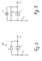
- Fig. 2 shows the first Construction of a well-known multivibrator.
- the multivibrator 22 has a flip-flop a Schmitt trigger 1, which in its feedback branch with the resistor 2 and the capacitor 3 is connected.
- the multivibrator swings up automatically its natural frequency, the capacitor 3 through the resistor 2 to the switch-off level of the Schmitt trigger and then back to the switch-on level is discharged.
- the Schmitt trigger 1 has two stable at its output States so that a periodic square wave signal is produced at output 4.
- Fig. 3 shows the connection of an ultrasonic vibrator with the feedback branch of the multivibrator according to FIG. 2.
- the ultrasonic vibrator consists of a piezo element 5, the piezo element 5 parallel to the resistor 2 is switched. After switching on, the circuit is initially on the natural frequency swing of the multivibrator. Because of the square wave signals at the output However, the piezo element 5 is also excited by square wave signals, whereby at the input of the Schmitt trigger 1 a periodic signal with the resonance frequency of the piezo element 5 is formed. This in turn will also be at the exit 4 square wave signals with the frequency of the resonance frequency of the piezo element 5 generated so that the circuit finally on the resonance frequency of Piezo element swings.
- Fig. 1 shows an electrical circuit of an air bubble detector with the invention Ultrasound transmitter.
- the air bubble detector consists of an ultrasonic transmitter 20, an ultrasonic receiver 21 and one inserted between them medical hose 11, in which air bubbles are reliably detected should.
- the ultrasonic transmitter 20 differs from the circuit shown in FIG Fig. 3 characterized in that at the output of the Schmitt trigger 1 an additional low pass 6, 7th is provided and that the input of the Schmitt trigger with a test input 9th is logically interconnected.
- the low pass consists of the resistor 6 and the capacitor 7 and causes the ultrasonic transducer on the one hand to be safely on its lowest Resonance frequency oscillates and that on the other hand the voltage at the ultrasonic oscillator 5 is approximately sinusoidal.
- test input 9 is carried out by an AND gate 10.
- An ultrasound receiver is located on the opposite side of the medical tube 11 21, which has a structurally identical piezo element 12.
- the voltage on the piezo element 12 is rectified by the diodes 13, 14 and via the Operational amplifier 15 smoothed via resistor 16 and capacitor 17, so that the corresponding envelope signal is present at output 18.
- Get one Air bubble in the medical tube 11, so changes compared to the Liquid filled hose damping in the ultrasonic path between ultrasonic transmitters 20 and ultrasound receiver 21. This in turn changes the envelope signal at output 18, causing detection of air bubbles within the hose 11 is possible.
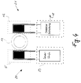
- FIG. 4 shows the schematic structure of the air bubble detector according to FIG. 1 with an ultrasonic transmitter 20 and an ultrasonic receiver 21.
- the ultrasonic transducers 5, 12 essentially consist of a piezo disk with two connections. These are opposite each other on the hose 11 to be monitored arranged so that the sound from the transmitter-side ultrasonic transducer 5 to the receiver Ultrasonic vibrator 12 can reach. Because of the necessary adjustment the piezo disks are connected to the acoustic impedance of the medical tube with a coupling medium suitable for this purpose to the medical Coupled hose. For this reason and to protect against damage the ultrasonic transducers are cast in a housing that is the corresponding one Bearing for the hose to be monitored forms.
- the ultrasonic transducer on the transmission side 5 is controlled by the transmitter 23 such that the ultrasonic oscillator 5 vibrates at its lowest resonance frequency.
- the receiving end Ultrasonic transducer 12 is constructed in the same way as the ultrasonic transducer on the transmission side, so that its greatest sensitivity to the transmission frequency of the ultrasonic transmitter 20 falls. In this way you get the largest possible output signal 18 on the ultrasound receiver 21, which is easy to evaluate.
Abstract
Description
Die Erfindung betrifft einen Ultraschallsender, insbesondere für einen Luftblasendetektor, mit einer Sendestufe und mit einem Ultraschallschwinger. Der Ultraschallschwinger besteht üblicherweise aus einem Piezo-Element, das auf einer seiner Resonanzfrequenzen betrieben wird. Hierbei stellt sich das Problem, eine Sendestufe bereitzustellen, die den Ultraschallschwinger auf eben dieser Resonanzfrequenz anregt, damit am Ultraschallschwinger ein möglichst starkes Ausgangssignal erzeugt wird.The invention relates to an ultrasonic transmitter, in particular for an air bubble detector, with a transmission stage and with an ultrasonic transducer. The ultrasonic transducer usually consists of a piezo element that is at one of its resonance frequencies is operated. Here the problem arises, a broadcast stage to provide, which excites the ultrasonic vibrator at precisely this resonance frequency, so that the ultrasonic transducer generates the strongest possible output signal becomes.
Wird der Ultraschallsender in einem Luftblasendetektor eingesetzt, so sind an den Ultraschallsender auch besondere Anforderungen hinsichtlich der Zuverlässigkeit zu stellen. Bei einem Luftblasendetektor befindet sich zwischen dem Ultraschallsender und einem entsprechend angeordneten Ultraschallempfänger ein Schlauch, der auf Luftblasen überwacht werden soll. Bei der Verabreichung von Infusionen oder bei der Durchführung von Transfusionen muß ein Lufteintritt in die hierbei verwendeten Schläuche unbedingt erkannt werden, da für den Patienten ansonsten lebensbedrohliche Situationen entstehen können. Zur Erkennung der Luftblasen wird dabei die Tatsache ausgenutzt, daß sich die Dämpfung der Ultraschallstrecke verändert, sobald eine Luftblase in den zwischen dem Ultraschallsender und dem Ultraschallempfänger befindlichen Schlauch eintritt.If the ultrasonic transmitter is used in an air bubble detector, the Ultrasonic transmitters also have special reliability requirements put. An air bubble detector is located between the ultrasound transmitter and a correspondingly arranged ultrasound receiver, a hose that Air bubbles should be monitored. When administering infusions or when Transfusions must be carried out using an air inlet Hoses must be recognized because otherwise life-threatening for the patient Situations can arise. To detect the air bubbles, the Taking advantage of the fact that the attenuation of the ultrasound path changes as soon as an air bubble in the between the ultrasonic transmitter and the ultrasonic receiver located hose enters.
Aus der US 5 583 280 ist ein Luftblasendetektor mit einer Sendestufe bekannt, die einen Frequenzgenerator umfaßt, der innerhalb eines bestimmten Frequenzbereiches linear durchgestimmt wird, wobei eine Resonanzfrequenz des Ultraschallschwingers ebenfalls in diesem Frequenzbereich liegt. Sobald der durchstimmende Frequenzgenerator die Resonanzfrequenz des Ultraschallschwingers trifft, findet eine Anregung des Ultraschallschwingers statt und die Durchstimmung des Frequenzgenerators kann von neuem beginnen.From US 5 583 280 an air bubble detector with a transmission stage is known, the comprises a frequency generator operating within a certain frequency range is tuned linearly, with a resonance frequency of the ultrasonic vibrator also lies in this frequency range. As soon as the tuning Frequency generator hits the resonance frequency of the ultrasonic transducer, finds one Excitation of the ultrasonic vibrator takes place and tuning of the frequency generator can start again.
Aus der EP 0 416 911 A2 ist ebenfalls ein Luftblasendetektor mit einer Sendestufe bekannt, die einen variablen Frequenzgenerator aufweist, wobei zusätzlich eine Testschaltung zum Erkennen von Fehlfunktionen vorgesehen ist.From EP 0 416 911 A2 there is also an air bubble detector with a transmission stage known, which has a variable frequency generator, with an additional Test circuit for detecting malfunctions is provided.
Aus der EP 0 340 470 A1 ist ein Flüssigkeitszerstäuber mit einem Ultraschallschwinger bekannt, wobei zur Anregung des Ultraschallschwingers ein spannungsgesteuerter Oszillator vorgesehen ist. Dieser wird mit einem Dreieckgenerator so geregelt, daß seine Frequenz in einem die Serienresonanz des Ultraschallschwingers umschließenden Bereich periodisch gewobbelt wird. Mit Hilfe einer überlagerten Regelschleife läßt sich erreichen, daß der spannungsgesteuerte Oszillator auf der Serien-Resonanzfrequenz des Ultraschallschwingers einrastet.EP 0 340 470 A1 describes a liquid atomizer with an ultrasonic oscillator known, a voltage-controlled to excite the ultrasonic vibrator Oscillator is provided. This is regulated with a triangle generator so that its frequency encompasses the series resonance of the ultrasonic transducer Area is swept periodically. With the help of a superimposed control loop can be achieved that the voltage controlled oscillator at the series resonance frequency of the ultrasonic transducer engages.
Aus der EP 0 084 485 A2 ist ebenfalls ein Flüssigkeitszerstäuber mit einem Ultraschallschwinger bekannt. Zur Anregung des Ultraschallschwingers sind ein Multivibrator und ein Impuls-Generator derart verschaltet, daß der Impulsgenerator im Takt der Eigenfrequenz des Multivibrators Impulse an den Ultraschallschwinger abgibt. Der Impuls wirkt auf den Ultraschallschwinger als eine Systemanregung, so daß der Ultraschallschwinger auf den Impuls mit einer gedämpften Resonanzschwingung reagiert. Beim Impulsbetrieb besteht allerdings grundsätzlich der Nachteil, daß immer ein Impulsgenerator mit einem entsprechenden Energiespeicher zur Bereitstellung der Impulsenergie benötigt wird, was einen verhältnismäßig hohen Schaltungsaufwand zur Folge hat.EP 0 084 485 A2 also describes a liquid atomizer with an ultrasonic oscillator known. A multivibrator is used to excite the ultrasonic vibrator and a pulse generator is connected in such a way that the pulse generator is clocked outputs the natural frequency of the multivibrator to the ultrasonic transducer. The pulse acts on the ultrasonic transducer as a system excitation, so that the Ultrasonic transducer on the pulse with a damped resonance vibration responds. In pulse operation, however, there is always the disadvantage that always a pulse generator with an appropriate energy storage for provision the pulse energy is required, which is a relatively high circuit outlay has the consequence.
Weiterhin ist aus der US 5,583,280 ein Flüssigkeitsstandanzeiger nach dem Ultraschallprinzip bekannt, wobei zur Anregung des Ultraschallschwingers ein rückgekoppeltes Bandpaßfilter verwendet wird, das ähnlich wie bei einer PLL-Schaltung auf die Resonanzfrequenz des Ultraschallschwingers einrastet.Furthermore, a liquid level indicator based on the ultrasound principle is known from US Pat. No. 5,583,280 known, with a feedback to excite the ultrasonic vibrator Bandpass filter is used, which is similar to a PLL circuit on the Resonance frequency of the ultrasonic transducer engages.
Ein Nachteil der aus dem Stand der Technik bekannten Ultraschallsender besteht darin, daß die Sendestufen einen verhältnismäßig hohen Schaltungsaufwand aufweisen.A disadvantage of the ultrasound transmitter known from the prior art is in the fact that the transmission stages have a relatively high circuit complexity.
Aufgabe der Erfindung ist es daher, einen Ultraschallsender zu schaffen, dessen Sendestufe zur Anregung des sendeseitigen Ultraschallschwingers einfach aufgebaut ist und gleichzeitig ein starkes Ausgangssignal am Ultraschallschwinger erzeugt.The object of the invention is therefore to provide an ultrasonic transmitter, the Transmitter stage for excitation of the ultrasonic transducer on the transmitter side is simply constructed is and at the same time generates a strong output signal on the ultrasonic transducer.
Diese Aufgabe wird mit den Merkmalen des Patentanspruchs 1 gelöst.This object is achieved with the features of
Die erfindungsgemäße Lösung besteht darin, daß die Sendestufe einen Multivibrator aufweist, der in an sich bekannter Weise aus einer Kippschaltung und einem im Rückkopplungszweig der Kippschaltung verschalteten Zeitglied besteht. In dieser Form schwingt der Multivibrator bereits selbsttätig auf seiner Eigenfrequenz an, die im wesentlichen durch das Zeitglied beeinflußt ist. Erfindungsgemäß wird der Ultraschallschwinger mit dem Rückkopplungszweig der Kippschaltung derart verschaltet, daß die Sendestufe auf oder in der Nähe einer Resonanzfrequenz des Ultraschallschwingers schwingt. Im Gegensatz zu bekannten Anregerschaltungen arbeitet der Ultraschallschwinger damit selbst als frequenzbestimmendes Bauteil für eine kontinuierlich erzeugte Sendefrequenz. Dies spart erheblichen Schaltungsaufwand, gleichzeitig erhält man dadurch eine besonders unempfindliche Anordnung gegenüber elektromagnetischen Störungen, wodurch wiederum die Zuverlässigkeit erhöht wird. Der erfindungsgemäße Ultraschallsender generiert zudem ein sehr starkes Ausgangssignal, das wiederum eine einfach aufzubauende Empfängerschaltung ermöglicht.The solution according to the invention is that the transmitter stage is a multivibrator has in a manner known per se from a flip-flop and an im Feedback branch of the flip-flop interconnected timer exists. In this The multivibrator automatically swings in shape at its natural frequency is essentially influenced by the timing element. According to the ultrasonic vibrator connected to the feedback branch of the multivibrator in such a way that the transmitter stage at or near a resonance frequency of the ultrasonic vibrator swings. In contrast to known excitation circuits, the works Ultrasonic transducer itself as a frequency-determining component for a continuous generated transmission frequency. This saves considerable circuit effort, at the same time, this gives a particularly insensitive arrangement electromagnetic interference, which in turn increases reliability becomes. The ultrasonic transmitter according to the invention also generates a very strong one Output signal, which in turn enables an easily constructed receiver circuit.
Nach einer bevorzugten Ausführungsform ist vorgesehen, daß das Zeitglied des Multivibrators aus mindestens einem RC-Glied besteht und daß der Ultraschallschwinger parallel zum Widerstand eines RC-Gliedes geschaltet ist. Auf diese Weise ist ein sicheres Anschwingen der Schaltung gewährleistet, da der Multivibrator zunächst sicher auf seiner Eigenfrequenz anschwingt und sodann aufgrund der sprunghaften Pegeländerungen am Ausgang der Kippschaltung den Ultraschallschwinger auf einer Resonanzfrequenz anregt.According to a preferred embodiment it is provided that the timer of Multivibrators consists of at least one RC element and that the ultrasonic vibrator is connected in parallel to the resistance of an RC element. In this way a safe start of the circuit is guaranteed, because the multivibrator first surges at its natural frequency and then due to the abrupt level changes at the output of the trigger circuit the ultrasonic transducer excited at a resonance frequency.
Nach einer weiteren bevorzugten Ausführungsform ist am Ausgang der Kippschaltung ein Tiefpaß vorgesehen, um ein Anschwingen des Ultraschallschwingers auf dessen Oberschwingungen zu unterdrücken. Ein definiertes Anschwingen kann zusätzlich auch dadurch erreicht werden, daß die Sendestufe unterhalb der entsprechenden Resonanzfrequenz des Ultraschallschwingers schwingt.According to a further preferred embodiment, the flip-flop is at the output a low-pass filter is provided to prevent the ultrasonic vibrator from vibrating to suppress its harmonics. A defined oscillation can additionally can also be achieved in that the transmission stage below the corresponding Resonance frequency of the ultrasonic vibrator swings.
Zweckmäßigerweise wird der Ultraschallschwinger auf seiner untersten Serien-Resonanzfrequenz betrieben. Handelt es sich bei dem Ultraschallschwinger beispielsweise um eine Piezo-Element, so ist die Serien-Resonanzfrequenz von äußeren Einflüssen weitgehend unabhängig, während in die Parallelresonanzfrequenz die schlecht definierte Elektrodenkapazität des Piezo-Elements eingeht.The ultrasonic vibrator is expediently at its lowest series resonance frequency operated. Is it the ultrasonic transducer, for example around a piezo element, so is the series resonance frequency from outside Influences largely independent, while in the parallel resonance frequency poorly defined electrode capacity of the piezo element is received.
Nach einer weiteren bevorzugten Ausführungsform ist vorgesehen, daß die Sendestufe logisch mit einem Testeingang verschaltet ist, um den Ultraschallsender zu Testzwecken gezielt zu aktivieren bzw. zu deaktivieren. Zweckmäßigerweise ist dabei der Testeingang mit einem Und-Gatter mit dem Eingang der Kippschaltung verschaltet. Auf diese Weise kann der Ultraschallsender für sicherheitstechnische Anwendungen gezielt getestet werden. According to a further preferred embodiment it is provided that the transmission stage is logically connected to a test input in order to close the ultrasonic transmitter Activate or deactivate specific test purposes. It is convenient to do so the test input with an AND gate is connected to the input of the flip-flop. In this way, the ultrasonic transmitter can be used for safety-related applications be tested specifically.
Nach einer weiteren bevorzugten Ausführungsform ist vorgesehen, daß die Kippschaltung ein Schmitt-Trigger ist. Ein herkömmlicher Schmitt-Trigger ist als integriertes Bauelement leicht verfügbar und wird durch ein Zeitglied im Rückkopplungszweig kaum belastet, so daß sich für die Wahl der Bauelemente des Zeitgliedes ein großer Spielraum ergibt.According to a further preferred embodiment it is provided that the flip-flop is a Schmitt trigger. A conventional Schmitt trigger is integrated Component readily available and is provided by a timing element in the feedback branch hardly burdened, so that there is a great choice for the selection of the components of the timer There is scope.
Ein Luftblasendetektor, für den selbständiger Schutz beansprucht wird, besteht aus dem erfindungsgemäßen Ultraschallsender, aus einem Ultraschallempfänger und einem zwischen Ultraschallsender und Ultraschallempfänger eingebrachten Schlauch.An air bubble detector, for which independent protection is claimed, consists of the ultrasonic transmitter according to the invention, from an ultrasonic receiver and one placed between the ultrasonic transmitter and the ultrasonic receiver Tube.
Weitere Einzelheiten und Vorteile der Erfindung werden anhand mehrerer in der Zeichnung dargestellter Ausführungsbeispiele erläutert. In dieser zeigt:
- Fig. 1
- eine elektrische Schaltung eines Luftblasendetektors mit dem erfindungsgemäßen Ultraschallsender,
- Fig. 2
- einen bekannten Multivibrator,
- Fig. 3
- die Verschaltung eines Ultraschallschwingers mit dem Rückkopplungszweig des Multivibrators gemäß Fig. 2 und
- Fig. 4
- den schematischen Aufbau des Luftblasendetektors.
- Fig. 1
- an electrical circuit of an air bubble detector with the ultrasonic transmitter according to the invention,
- Fig. 2
- a well-known multivibrator,
- Fig. 3
- the connection of an ultrasonic vibrator with the feedback branch of the multivibrator according to FIG. 2 and
- Fig. 4
- the schematic structure of the bubble detector.
Bevor auf die Funktion des Ultraschallsenders gemäß Fig. 1 eingegangen wird, wird
das Funktionsprinzip anhand der Fig. 2 und 3 erläutert. Fig. 2 zeigt zunächst den
Aufbau eines bekannten Multivibrators. Der Multivibrator 22 weist als Kippschaltung
einen Schmitt-Trigger 1 auf, der in seinem Rückkopplungszweig mit dem Widerstand
2 und dem Kondensator 3 verschaltet ist. Der Multivibrator schwingt selbsttätig auf
seiner Eigenfrequenz, wobei der Kondensator 3 über den Widerstand 2 bis zum Ausschaltpegel
des Schmitt-Triggers aufgeladen und anschließend wieder bis zum Einschaltpegel
entladen wird. Der Schmitt-Trigger 1 weist an seinem Ausgang zwei stabile
Zustände auf, so daß am Ausgang 4 ein periodisches Rechtecksignal entsteht. Before the function of the ultrasound transmitter according to FIG. 1 is discussed
the operating principle explained with reference to FIGS. 2 and 3. Fig. 2 shows the first
Construction of a well-known multivibrator. The
Fig. 3 zeigt die Verschaltung eines Ultraschallschwingers mit dem Rückkopplungszweig
des Multivibrators gemäß Fig. 2. Der Ultraschallschwinger besteht dabei aus
einem Piezo-Element 5, wobei das Piezo-Element 5 parallel zu dem Widerstand 2
geschaltet ist. Nach dem Einschalten wird die Schaltung zunächst auf der Eigenfrequenz
des Multivibrators anschwingen. Aufgrund der Rechtecksignale am Ausgang
wird allerdings das Piezo-Element 5 ebenfalls durch Rechtecksignale angeregt, wodurch
am Eingang des Schmitt-Triggers 1 ein periodisches Signal mit der Resonanzfrequenz
des Piezo-Elements 5 entsteht. Hierdurch wiederum werden auch am Ausgang
4 Rechtecksignale mit der Frequenz der Resonanzfrequenz des Piezo-Elements
5 erzeugt, so daß die Schaltung schließlich auf der Resonanzfrequenz des
Piezo-Elements schwingt.Fig. 3 shows the connection of an ultrasonic vibrator with the feedback branch
of the multivibrator according to FIG. 2. The ultrasonic vibrator consists of
a piezo element 5, the piezo element 5 parallel to the
Fig. 1 zeigt eine elektrische Schaltung eines Luftblasendetektors mit dem erfindungsgemäßen
Ultraschallsender. Der Luftblasendetektor besteht aus einem Ultraschallsender
20, einem Ultraschallempfänger 21 und einem dazwischen eingebrachten
medizinischen Schlauch 11, bei dem Luftblasen sicher detektiert werden
sollen. Der Ultraschallsender 20 unterscheidet sich gegenüber der Schaltung gemäß
Fig. 3 dadurch, daß am Ausgang des Schmitt-Triggers 1 zusätzlich ein Tiefpaß 6, 7
vorgesehen ist und daß der Eingang des Schmitt-Triggers mit einem Testeingang 9
logisch verschaltet ist. Der Tiefpaß besteht aus dem Widerstand 6 und dem Kondensator
7 und bewirkt, daß der Ultraschallschwinger zum einen sicher auf seiner untersten
Resonanzfrequenz anschwingt und daß zum anderen die Spannung am Ultraschallschwinger
5 annähernd sinusförmig ist. Die Verschaltung des Testeingangs 9
mit dem Rückkopplungszweig 8 erfolgt durch ein Und-Gatter 10. Hierdurch kann der
Schmitt-Trigger 1 zu Testzwecken sicher aktiviert oder deaktiviert werden. Auf der
gegenüberliegenden Seite des medizinischen Schlauches 11 befindet sich ein Ultraschallempfänger
21, der ein baugleiches Piezo-Element 12 aufweist. Die Spannung
am Piezo-Element 12 wird durch die Dioden 13, 14 gleichgerichtet und über den
Operationsverstärker 15 über den Widerstand 16 und den Kondensator 17 geglättet,
so daß am Ausgang 18 das entsprechende Hüllkurvensignal anliegt. Gelangt eine
Luftblase in den medizinischen Schlauch 11, so verändert sich gegenüber dem mit
Flüssigkeit gefüllten Schlauch die Dämpfung in der Ultraschallstrecke zwischen Ultraschallsender
20 und Ultraschallempfänger 21. Hierdurch wiederum verändert sich
das Hüllkurvensignal am Ausgang 18, wodurch eine Detektion von Luftblasen innerhalb
des Schlauches 11 möglich ist.Fig. 1 shows an electrical circuit of an air bubble detector with the invention
Ultrasound transmitter. The air bubble detector consists of an
Fig. 4 zeigt den schematischen Aufbau des Luftblasendetektors gemäß Fig. 1 mit
einem Ultraschallsender 20 und einem Ultraschallempfänger 21. Die Ultraschallschwinger
5, 12 bestehen im wesentlichen aus einer Piezoscheibe mit zwei Anschlüssen.
Diese sind an dem zu überwachenden Schlauch 11 gegenüberliegend
angeordnet, so daß der Schall vom sendeseitigen Ultraschallschwinger 5 zum empfangsseitigen
Ultraschallschwinger 12 gelangen kann. Wegen der nötigen Anpassung
an die akustische Impedanz des medizinischen Schlauches sind die Piezoscheiben
mit einem für diesen Zweck geeigneten Koppelmedium an den medizinischen
Schlauch angekoppelt. Aus diesem Grund und zum Schutz vor Beschädigung
sind die Ultraschallschwinger in ein Gehäuse eingegossen, das gleichzeitig das entsprechende
Lager für den zu überwachenden Schlauch bildet. Der sendeseitige Ultraschallschwinger
5 wird von der Sendestufe 23 derart angesteuert, daß der Ultraschallschwinger
5 auf seiner untersten Resonanzfrequenz schwingt. Der empfangsseitige
Ultraschallschwinger 12 ist gleich aufgebaut wie der sendeseitige Ultraschallschwinger,
so daß dessen größte Empfindlichkeit auf die Sendefrequenz des Ultraschallsenders
20 fällt. Auf diese Weise erhält man ein größtmögliches Ausgangssignal
18 am Ultraschallempfänger 21, das einfach auszuwerten ist.FIG. 4 shows the schematic structure of the air bubble detector according to FIG. 1 with
an
Claims (11)
dadurch gekennzeichnet,
characterized,
Applications Claiming Priority (2)
| Application Number | Priority Date | Filing Date | Title |
|---|---|---|---|
| DE19738146 | 1997-09-01 | ||
| DE19738146A DE19738146B4 (en) | 1997-09-01 | 1997-09-01 | Ultrasonic transmitter, in particular for an air bubble detector |
Publications (3)
| Publication Number | Publication Date |
|---|---|
| EP0899564A2 true EP0899564A2 (en) | 1999-03-03 |
| EP0899564A3 EP0899564A3 (en) | 2005-01-12 |
| EP0899564B1 EP0899564B1 (en) | 2010-08-25 |
Family
ID=7840845
Family Applications (1)
| Application Number | Title | Priority Date | Filing Date |
|---|---|---|---|
| EP98116031A Expired - Lifetime EP0899564B1 (en) | 1997-09-01 | 1998-08-25 | Ultrasonic transmitter, in particular for air-bubble detection |
Country Status (5)
| Country | Link |
|---|---|
| US (1) | US6212936B1 (en) |
| EP (1) | EP0899564B1 (en) |
| JP (1) | JP4138091B2 (en) |
| DE (2) | DE19738146B4 (en) |
| ES (1) | ES2348766T3 (en) |
Cited By (1)
| Publication number | Priority date | Publication date | Assignee | Title |
|---|---|---|---|---|
| DE10338940B3 (en) * | 2003-08-22 | 2005-02-10 | Fresenius Medical Care Deutschland Gmbh | Measuring ultrasonic signal transit time within a fluid flow, especially external blood flow in dialysis, with received signal scanned during at least one half-period to give contact points with a static level |
Families Citing this family (30)
| Publication number | Priority date | Publication date | Assignee | Title |
|---|---|---|---|---|
| DE10209254B4 (en) * | 2002-02-27 | 2004-07-29 | SONOTEC Dr. zur Horst-Meyer & Münch oHG | Ultrasonic device for the detection of gas bubbles |
| US7934912B2 (en) | 2007-09-27 | 2011-05-03 | Curlin Medical Inc | Peristaltic pump assembly with cassette and mounting pin arrangement |
| US8083503B2 (en) | 2007-09-27 | 2011-12-27 | Curlin Medical Inc. | Peristaltic pump assembly and regulator therefor |
| US8062008B2 (en) | 2007-09-27 | 2011-11-22 | Curlin Medical Inc. | Peristaltic pump and removable cassette therefor |
| US8517990B2 (en) | 2007-12-18 | 2013-08-27 | Hospira, Inc. | User interface improvements for medical devices |
| US20090259214A1 (en) * | 2008-04-09 | 2009-10-15 | Searete Llc, A Limited Liability Corporation Of The State Of Delaware | Agent delivery device |
| US20090259217A1 (en) * | 2008-04-09 | 2009-10-15 | Searete Llc, A Limited Liability Corporation Of The State Of Delaware | Methods and systems associated with delivery of one or more agents to an individual |
| US8120500B2 (en) * | 2008-12-08 | 2012-02-21 | Ecolab Inc. | Acoustic fluid presence/absence detection |
| US9240002B2 (en) | 2011-08-19 | 2016-01-19 | Hospira, Inc. | Systems and methods for a graphical interface including a graphical representation of medical data |
| US10022498B2 (en) | 2011-12-16 | 2018-07-17 | Icu Medical, Inc. | System for monitoring and delivering medication to a patient and method of using the same to minimize the risks associated with automated therapy |
| JP6306566B2 (en) | 2012-03-30 | 2018-04-04 | アイシーユー・メディカル・インコーポレーテッド | Air detection system and method for detecting air in an infusion system pump |
| CA3089257C (en) | 2012-07-31 | 2023-07-25 | Icu Medical, Inc. | Patient care system for critical medications |
| AU2014268355B2 (en) | 2013-05-24 | 2018-06-14 | Icu Medical, Inc. | Multi-sensor infusion system for detecting air or an occlusion in the infusion system |
| ES2845748T3 (en) | 2013-05-29 | 2021-07-27 | Icu Medical Inc | Infusion system and method of use that prevent oversaturation of an analog-digital converter |
| EP3003441B1 (en) | 2013-05-29 | 2020-12-02 | ICU Medical, Inc. | Infusion system which utilizes one or more sensors and additional information to make an air determination regarding the infusion system |
| AU2015222800B2 (en) | 2014-02-28 | 2019-10-17 | Icu Medical, Inc. | Infusion system and method which utilizes dual wavelength optical air-in-line detection |
| AU2015266706B2 (en) | 2014-05-29 | 2020-01-30 | Icu Medical, Inc. | Infusion system and pump with configurable closed loop delivery rate catch-up |
| US11344668B2 (en) | 2014-12-19 | 2022-05-31 | Icu Medical, Inc. | Infusion system with concurrent TPN/insulin infusion |
| US10850024B2 (en) | 2015-03-02 | 2020-12-01 | Icu Medical, Inc. | Infusion system, device, and method having advanced infusion features |
| DE102015103938A1 (en) | 2015-03-17 | 2016-09-22 | B. Braun Avitum Ag | Ultrasonic-based gas bubble and / or solid-state detector, dialysis machine and method for such a detector |
| US10081125B2 (en) | 2015-07-20 | 2018-09-25 | International Business Machines Corporation | Method to detect and remove gas bubbles from molten substrate to prevent hollow fiber formation |
| WO2017197024A1 (en) | 2016-05-13 | 2017-11-16 | Icu Medical, Inc. | Infusion pump system and method with common line auto flush |
| WO2017214441A1 (en) | 2016-06-10 | 2017-12-14 | Icu Medical, Inc. | Acoustic flow sensor for continuous medication flow measurements and feedback control of infusion |
| US10072962B2 (en) * | 2016-07-05 | 2018-09-11 | Ecolab Usa Inc. | Liquid out-of-product alarm system and method |
| US9863875B1 (en) | 2016-10-19 | 2018-01-09 | International Business Machines Corporation | In-situ detection of hollow glass fiber formation |
| US10089055B1 (en) | 2017-12-27 | 2018-10-02 | Icu Medical, Inc. | Synchronized display of screen content on networked devices |
| US10922961B2 (en) | 2019-03-13 | 2021-02-16 | Fresenius Medical Care Holdings, Inc. | Remote communication with multiple dialysis machines |
| US11278671B2 (en) | 2019-12-04 | 2022-03-22 | Icu Medical, Inc. | Infusion pump with safety sequence keypad |
| EP4185260A1 (en) | 2020-07-21 | 2023-05-31 | ICU Medical, Inc. | Fluid transfer devices and methods of use |
| US11135360B1 (en) | 2020-12-07 | 2021-10-05 | Icu Medical, Inc. | Concurrent infusion with common line auto flush |
Citations (4)
| Publication number | Priority date | Publication date | Assignee | Title |
|---|---|---|---|---|
| US4015464A (en) * | 1975-02-21 | 1977-04-05 | The Washington University | Ultrasonic continuous wave particle monitor |
| US4736192A (en) * | 1983-08-10 | 1988-04-05 | Siemens Aktiengesellschaft | Excitation circuit for piezo-electric sound generators |
| EP0496436A2 (en) * | 1987-05-01 | 1992-07-29 | Abbott Laboratories | Device for detecting the absence of a liquid in a conduit |
| EP0643301A1 (en) * | 1993-09-10 | 1995-03-15 | Cobe Laboratories, Inc. | Method and apparatus for ultrasonic detection of air bubbles |
Family Cites Families (15)
| Publication number | Priority date | Publication date | Assignee | Title |
|---|---|---|---|---|
| US3520186A (en) | 1968-03-11 | 1970-07-14 | Nat Sonics Corp | Ultrasonic fluid interface sensing |
| JPS5113430B1 (en) * | 1970-02-10 | 1976-04-28 | ||
| FR2077968A1 (en) * | 1970-02-27 | 1971-11-05 | Thomson Csf | |
| SE351303B (en) * | 1971-04-02 | 1972-11-20 | Bofors Ab | |
| US3974681A (en) * | 1973-10-23 | 1976-08-17 | Jerry Namery | Ultrasonic bubble detector |
| US4130010A (en) * | 1977-08-15 | 1978-12-19 | Westinghouse Electric Corp. | Bubble detector |
| US4138879A (en) * | 1977-08-22 | 1979-02-13 | Tif Instruments, Inc. | Sightless bubble detector |
| US4235095A (en) * | 1978-09-01 | 1980-11-25 | Tif Instruments, Inc. | Device for detecting inhomogeneities such as gas bubbles |
| ATE34838T1 (en) * | 1980-03-20 | 1988-06-15 | Acumet Precision Instr Ltd | METHOD AND APPARATUS FOR DETERMINING PHYSICAL QUANTITIES, IN PARTICULAR LENGTH-RELATED QUANTITIES. |
| CA1206996A (en) | 1982-01-18 | 1986-07-02 | Naoyoshi Maehara | Ultrasonic liquid ejecting apparatus |
| US4542644A (en) * | 1983-09-26 | 1985-09-24 | The United States Of America As Represented By The United States Department Of Energy | Void/particulate detector |
| EP0340470A1 (en) | 1988-05-06 | 1989-11-08 | Satronic Ag | Method and circuit for driving an ultrasonic transducer, and their use in atomizing a liquid |
| US5053747A (en) | 1989-09-05 | 1991-10-01 | Pacesetter Infusion, Inc. | Ultrasonic air-in-line detector self-test technique |
| US4994765A (en) * | 1990-04-04 | 1991-02-19 | North American Philips Corporation | Stabilized gated oscillator utilizing a ceramic resonator |
| US5583280A (en) | 1995-01-26 | 1996-12-10 | Abbott Laboratories | Air bubble sensor with simplified mounting of piezo elements |
-
1997
- 1997-09-01 DE DE19738146A patent/DE19738146B4/en not_active Expired - Fee Related
-
1998
- 1998-08-25 ES ES98116031T patent/ES2348766T3/en not_active Expired - Lifetime
- 1998-08-25 DE DE59814467T patent/DE59814467D1/en not_active Expired - Lifetime
- 1998-08-25 EP EP98116031A patent/EP0899564B1/en not_active Expired - Lifetime
- 1998-08-28 JP JP24368298A patent/JP4138091B2/en not_active Expired - Fee Related
- 1998-09-01 US US09/145,057 patent/US6212936B1/en not_active Expired - Lifetime
Patent Citations (4)
| Publication number | Priority date | Publication date | Assignee | Title |
|---|---|---|---|---|
| US4015464A (en) * | 1975-02-21 | 1977-04-05 | The Washington University | Ultrasonic continuous wave particle monitor |
| US4736192A (en) * | 1983-08-10 | 1988-04-05 | Siemens Aktiengesellschaft | Excitation circuit for piezo-electric sound generators |
| EP0496436A2 (en) * | 1987-05-01 | 1992-07-29 | Abbott Laboratories | Device for detecting the absence of a liquid in a conduit |
| EP0643301A1 (en) * | 1993-09-10 | 1995-03-15 | Cobe Laboratories, Inc. | Method and apparatus for ultrasonic detection of air bubbles |
Cited By (2)
| Publication number | Priority date | Publication date | Assignee | Title |
|---|---|---|---|---|
| DE10338940B3 (en) * | 2003-08-22 | 2005-02-10 | Fresenius Medical Care Deutschland Gmbh | Measuring ultrasonic signal transit time within a fluid flow, especially external blood flow in dialysis, with received signal scanned during at least one half-period to give contact points with a static level |
| US7694565B2 (en) | 2003-08-22 | 2010-04-13 | Fresenius Medical Care Deutschland Gmbh | Acoustic method for measuring a signal propagation time in a medical liquid and device for using this method |
Also Published As
| Publication number | Publication date |
|---|---|
| DE19738146B4 (en) | 2005-05-12 |
| ES2348766T3 (en) | 2010-12-13 |
| EP0899564B1 (en) | 2010-08-25 |
| JPH11133002A (en) | 1999-05-21 |
| US6212936B1 (en) | 2001-04-10 |
| JP4138091B2 (en) | 2008-08-20 |
| DE59814467D1 (en) | 2010-10-07 |
| DE19738146A1 (en) | 1999-03-11 |
| EP0899564A3 (en) | 2005-01-12 |
Similar Documents
| Publication | Publication Date | Title |
|---|---|---|
| EP0899564B1 (en) | Ultrasonic transmitter, in particular for air-bubble detection | |
| EP1540291B1 (en) | Oscillating level sensor | |
| DE3336991C2 (en) | ||
| EP2438407B1 (en) | Method for determining or monitoring of a predetermined level, phase boundary or density of a medium | |
| DE2512494C2 (en) | ||
| DE4311963C2 (en) | Level measuring device | |
| DE19621449C2 (en) | Vibration resonator, method for operating such a vibration resonator and vibration level limit switch with such a vibration resonator | |
| EP0684457A2 (en) | Ultrasound flow rate measuring apparatus | |
| EP1156305B1 (en) | Method for controlling a transducer arrangement in liquid level measurement apparatuses and device for curying out of the method | |
| DE10023306C2 (en) | Process for controlling piezoelectric drives in level measuring devices | |
| DE3348119C2 (en) | Device for ascertaining and/or monitoring a predetermined filling level in a container | |
| DE4322388A1 (en) | Circuit arrangement for the safe start of ultrasonic disintegrators | |
| DE2749077C2 (en) | Probe | |
| EP0311129A1 (en) | Inductive proximity sensor | |
| DE3625779A1 (en) | Apparatus for determining a specific level in a container | |
| DE19930896A1 (en) | Vibrating probe in level detector for fluent material | |
| DE3810669C2 (en) | Device for monitoring the level of a liquid | |
| DE10328113B4 (en) | Device for operating a vibratory unit of a vibration resonator | |
| DE102004050494A1 (en) | Device for determining and / or monitoring a process variable of a medium | |
| DE1673972B2 (en) | DEVICE FOR DISPLAYING THE LEVEL OF STORED GOODS IN CONTAINERS | |
| DE3134985A1 (en) | DEVICE FOR OPERATING RESONANCE FLOWMETERS | |
| DE3401979A1 (en) | Ultrasonic transducer | |
| DE102010062146B4 (en) | Apparatus for determining a degree of filling of a dust collecting container for a vacuum cleaner and vacuum cleaner | |
| DE10341436B4 (en) | Sensor for detecting transparent object structures | |
| EP2848814B1 (en) | Sensor for dry running protection |
Legal Events
| Date | Code | Title | Description |
|---|---|---|---|
| PUAI | Public reference made under article 153(3) epc to a published international application that has entered the european phase |
Free format text: ORIGINAL CODE: 0009012 |
|
| AK | Designated contracting states |
Kind code of ref document: A2 Designated state(s): AT BE CH CY DE DK ES FI FR GB GR IE IT LI LU MC NL PT SE |
|
| AX | Request for extension of the european patent |
Free format text: AL;LT;LV;MK;RO;SI |
|
| PUAL | Search report despatched |
Free format text: ORIGINAL CODE: 0009013 |
|
| AK | Designated contracting states |
Kind code of ref document: A3 Designated state(s): AT BE CH CY DE DK ES FI FR GB GR IE IT LI LU MC NL PT SE |
|
| AX | Request for extension of the european patent |
Extension state: AL LT LV MK RO SI |
|
| RAP1 | Party data changed (applicant data changed or rights of an application transferred) |
Owner name: FRESENIUS AG |
|
| 17P | Request for examination filed |
Effective date: 20050210 |
|
| AKX | Designation fees paid |
Designated state(s): DE ES FR GB IT |
|
| 17Q | First examination report despatched |
Effective date: 20071106 |
|
| GRAP | Despatch of communication of intention to grant a patent |
Free format text: ORIGINAL CODE: EPIDOSNIGR1 |
|
| GRAS | Grant fee paid |
Free format text: ORIGINAL CODE: EPIDOSNIGR3 |
|
| GRAA | (expected) grant |
Free format text: ORIGINAL CODE: 0009210 |
|
| AK | Designated contracting states |
Kind code of ref document: B1 Designated state(s): DE ES FR GB IT |
|
| REG | Reference to a national code |
Ref country code: GB Ref legal event code: FG4D Free format text: NOT ENGLISH |
|
| REF | Corresponds to: |
Ref document number: 59814467 Country of ref document: DE Date of ref document: 20101007 Kind code of ref document: P |
|
| REG | Reference to a national code |
Ref country code: ES Ref legal event code: FG2A Effective date: 20101129 |
|
| PLBE | No opposition filed within time limit |
Free format text: ORIGINAL CODE: 0009261 |
|
| STAA | Information on the status of an ep patent application or granted ep patent |
Free format text: STATUS: NO OPPOSITION FILED WITHIN TIME LIMIT |
|
| 26N | No opposition filed |
Effective date: 20110526 |
|
| REG | Reference to a national code |
Ref country code: DE Ref legal event code: R097 Ref document number: 59814467 Country of ref document: DE Effective date: 20110526 |
|
| PGFP | Annual fee paid to national office [announced via postgrant information from national office to epo] |
Ref country code: DE Payment date: 20140822 Year of fee payment: 17 |
|
| PGFP | Annual fee paid to national office [announced via postgrant information from national office to epo] |
Ref country code: GB Payment date: 20140821 Year of fee payment: 17 Ref country code: ES Payment date: 20140822 Year of fee payment: 17 |
|
| PGFP | Annual fee paid to national office [announced via postgrant information from national office to epo] |
Ref country code: IT Payment date: 20140819 Year of fee payment: 17 |
|
| PGFP | Annual fee paid to national office [announced via postgrant information from national office to epo] |
Ref country code: FR Payment date: 20140822 Year of fee payment: 17 |
|
| REG | Reference to a national code |
Ref country code: DE Ref legal event code: R119 Ref document number: 59814467 Country of ref document: DE |
|
| GBPC | Gb: european patent ceased through non-payment of renewal fee |
Effective date: 20150825 |
|
| PG25 | Lapsed in a contracting state [announced via postgrant information from national office to epo] |
Ref country code: IT Free format text: LAPSE BECAUSE OF NON-PAYMENT OF DUE FEES Effective date: 20150825 |
|
| REG | Reference to a national code |
Ref country code: FR Ref legal event code: ST Effective date: 20160429 |
|
| PG25 | Lapsed in a contracting state [announced via postgrant information from national office to epo] |
Ref country code: DE Free format text: LAPSE BECAUSE OF NON-PAYMENT OF DUE FEES Effective date: 20160301 Ref country code: GB Free format text: LAPSE BECAUSE OF NON-PAYMENT OF DUE FEES Effective date: 20150825 |
|
| PG25 | Lapsed in a contracting state [announced via postgrant information from national office to epo] |
Ref country code: FR Free format text: LAPSE BECAUSE OF NON-PAYMENT OF DUE FEES Effective date: 20150831 |
|
| REG | Reference to a national code |
Ref country code: ES Ref legal event code: FD2A Effective date: 20160926 |
|
| PG25 | Lapsed in a contracting state [announced via postgrant information from national office to epo] |
Ref country code: ES Free format text: LAPSE BECAUSE OF NON-PAYMENT OF DUE FEES Effective date: 20150826 |