EP0899436A1 - Internal combustion engine having pressure wave exchanger - Google Patents
Internal combustion engine having pressure wave exchanger Download PDFInfo
- Publication number
- EP0899436A1 EP0899436A1 EP97810616A EP97810616A EP0899436A1 EP 0899436 A1 EP0899436 A1 EP 0899436A1 EP 97810616 A EP97810616 A EP 97810616A EP 97810616 A EP97810616 A EP 97810616A EP 0899436 A1 EP0899436 A1 EP 0899436A1
- Authority
- EP
- European Patent Office
- Prior art keywords
- pressure wave
- wave machine
- catalyst
- engine
- combination according
- Prior art date
- Legal status (The legal status is an assumption and is not a legal conclusion. Google has not performed a legal analysis and makes no representation as to the accuracy of the status listed.)
- Granted
Links
Images


Classifications
-
- F—MECHANICAL ENGINEERING; LIGHTING; HEATING; WEAPONS; BLASTING
- F01—MACHINES OR ENGINES IN GENERAL; ENGINE PLANTS IN GENERAL; STEAM ENGINES
- F01N—GAS-FLOW SILENCERS OR EXHAUST APPARATUS FOR MACHINES OR ENGINES IN GENERAL; GAS-FLOW SILENCERS OR EXHAUST APPARATUS FOR INTERNAL-COMBUSTION ENGINES
- F01N3/00—Exhaust or silencing apparatus having means for purifying, rendering innocuous, or otherwise treating exhaust
- F01N3/08—Exhaust or silencing apparatus having means for purifying, rendering innocuous, or otherwise treating exhaust for rendering innocuous
- F01N3/10—Exhaust or silencing apparatus having means for purifying, rendering innocuous, or otherwise treating exhaust for rendering innocuous by thermal or catalytic conversion of noxious components of exhaust
- F01N3/18—Exhaust or silencing apparatus having means for purifying, rendering innocuous, or otherwise treating exhaust for rendering innocuous by thermal or catalytic conversion of noxious components of exhaust characterised by methods of operation; Control
- F01N3/20—Exhaust or silencing apparatus having means for purifying, rendering innocuous, or otherwise treating exhaust for rendering innocuous by thermal or catalytic conversion of noxious components of exhaust characterised by methods of operation; Control specially adapted for catalytic conversion
- F01N3/2006—Periodically heating or cooling catalytic reactors, e.g. at cold starting or overheating
-
- F—MECHANICAL ENGINEERING; LIGHTING; HEATING; WEAPONS; BLASTING
- F02—COMBUSTION ENGINES; HOT-GAS OR COMBUSTION-PRODUCT ENGINE PLANTS
- F02B—INTERNAL-COMBUSTION PISTON ENGINES; COMBUSTION ENGINES IN GENERAL
- F02B33/00—Engines characterised by provision of pumps for charging or scavenging
- F02B33/32—Engines with pumps other than of reciprocating-piston type
- F02B33/42—Engines with pumps other than of reciprocating-piston type with driven apparatus for immediate conversion of combustion gas pressure into pressure of fresh charge, e.g. with cell-type pressure exchangers
-
- Y—GENERAL TAGGING OF NEW TECHNOLOGICAL DEVELOPMENTS; GENERAL TAGGING OF CROSS-SECTIONAL TECHNOLOGIES SPANNING OVER SEVERAL SECTIONS OF THE IPC; TECHNICAL SUBJECTS COVERED BY FORMER USPC CROSS-REFERENCE ART COLLECTIONS [XRACs] AND DIGESTS
- Y02—TECHNOLOGIES OR APPLICATIONS FOR MITIGATION OR ADAPTATION AGAINST CLIMATE CHANGE
- Y02T—CLIMATE CHANGE MITIGATION TECHNOLOGIES RELATED TO TRANSPORTATION
- Y02T10/00—Road transport of goods or passengers
- Y02T10/10—Internal combustion engine [ICE] based vehicles
- Y02T10/12—Improving ICE efficiencies
Definitions
- the present invention relates to a Internal combustion engine with pressure wave machine and at least a catalyst according to the preamble of claim 1.
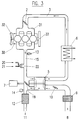
- the arrows in the channels indicate the course of the air and Gas flows, and you can see from this scheme that the Fresh air is sucked in at air inlet 8 and through that Air filter 9 and the charger throttle valve 10 in the Pressure wave machine 5 arrives. Most there the fresh air is compressed by the action of the exhaust gases and via the charge air cooler 6 and the throttle valve 2 to the engine 1 fed. A small part of the fresh air gets in Form of purge air, through the pressure wave machine 5 in the Exhaust 11 and mixes there with the exhaust gases. The Exhaust gases come from the internal combustion engine 1 via the Three-way catalyst 4 to the pressure wave machine 5 and get then, interspersed with fresh air, over the Oxidation catalytic converter 12 to the exhaust 11.
- the wastegate flap 19 can be opened if the boost pressure is too high so that part of the exhaust gases on the Pressure wave machine 5 is bypassed, whereby a smaller pressure ratio is generated. So you get one better overall efficiency for the drive unit and thus reduces fuel consumption.
- Wastegate flap can also other means known per se can be used to control the boost pressure.
- the charger throttle valve 10 is used to control the purge air. With it, the proportion of fresh air entering the exhaust reached, reduced. This will reduce the exhaust gas temperature the oxidation catalyst 12 increased so that this faster reaches its light-off temperature and thus a higher one Degree of conversion achieved.
- the signal from the temperature sensor 14 can be used as a size for controlling the loader throttle valve be used. As further tax parameters u. a. also the speed of the engine and the pressure after Throttle valve 2 serve.
- the lambda probe 13 delivers the Control variable for the mixture formation.
- the engine is operated with a lambda ratio of 1 or with a slight excess of fuel.
- the three-way catalytic converter in conjunction with the electronically controlled mixture preparation (lambda probe) is currently the most effective catalytic exhaust gas purification system. Simultaneous conversion of all three pollutant components is possible, whereby a stoichiometric fuel-air mixture (lambda 1) that is as precise as possible is required. These three components are HC, CO and NO x . By shifting the control range Lambda 1 to the richer side, however, the NO x can be converted and removed very efficiently. However, this would lead to a reduction in the conversion rate of the remaining two components and would therefore not make sense if only a three-way catalyst is used.
- a pressure wave machine increases the efficiency of the internal combustion engine and also makes it possible that an excess air is generated by the pressure wave machine in the exhaust system, where the use of an oxidation catalyst, whereby the remaining pollutants, which largely consist of HC and CO, is optimal can be converted. Depending on the catalyst coating, a substantial NO x conversion rate can also be achieved in the oxidation catalyst.
- Heaters e.g. an electrically operated heater, be used. It is important that both the function of the To influence the catalyst and the charger favorably.
- the use of a pressure wave machine with a gasoline engine thus enables a large increase in performance and, above all, the use of a downstream oxidation ⁇ catalytic converter, as a result of which the three-way catalytic converter can remove the one pollutant component, the NO x , more efficiently than with a conventionally used three-way catalytic converter, and on the other hand the remaining pollutants, HC and CO, can be removed by the excess air in the oxidation catalytic converter with a particularly high conversion rate.
- FIG. 4 An embodiment variant is shown in FIG that of the three-way catalyst divided into two parts 4A and 4B and the heater is between the two Catalyst parts located. This can make it efficient Heating of the catalyst and the entrance of the Pressure wave machine can be achieved.
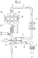
- FIG. 3 shows an internal combustion engine 30 which is a diesel engine, here too the intake manifold 31, the Fan 32 and the output 33 are shown.
- the Diesel engine does not have a regulated three-way catalytic converter, so that the heater 22, which can be the same as previously described, between the outlet of the Diesel engine and the exhaust gas inlet of the pressure wave machine is arranged.
- the oxidation catalyst 12 can also be used for a diesel engine can be used, the catalyst either between the pressure wave machine outlet and the Exhaust 11, as shown in Figure 3, or between the Motor outlet 15 and the exhaust gas inlet of the pressure wave machine, can be arranged as shown in Figure 4.
- the heater is as in Figure 3 drawn, and in the other case between the Oxidation catalyst and the exhaust gas inlet of the Pressure wave machine, as shown in Figure 4.
Landscapes
- Engineering & Computer Science (AREA)
- Chemical & Material Sciences (AREA)
- Combustion & Propulsion (AREA)
- Mechanical Engineering (AREA)
- General Engineering & Computer Science (AREA)
- Chemical Kinetics & Catalysis (AREA)
- Health & Medical Sciences (AREA)
- Toxicology (AREA)
- Exhaust Gas After Treatment (AREA)
- Supercharger (AREA)
- Exhaust Gas Treatment By Means Of Catalyst (AREA)
- Engine Equipment That Uses Special Cycles (AREA)
Abstract
Description
Die vorliegende Erfindung bezieht sich auf eine
Verbrennungsmaschine mit Druckwellenmaschine und mindestens
einem Katalysator gemäss dem Oberbegriff von Patentanspruch
1.The present invention relates to a
Internal combustion engine with pressure wave machine and at least
a catalyst according to the preamble of
Ein Otto-Motor mit Druckwellenmaschine ist in der nicht vorveröffentlichten PCT/CH97/00079-Anmeldung des gleichen Anmelders beschrieben. Dabei ist ausser der Kombination Otto-Motor mit einer Druckwellenmaschine, einem geregelten Dreiweg-Katalysator und einem Oxydations-Katalysator eine Heizeinrichtung beschrieben, die zwischen dem Motor-Auslass und dem Dreiweg-Katalysator angeordnet ist.There is no Otto engine with a pressure wave machine prepublished PCT / CH97 / 00079 application of the same Described by the applicant. Besides the combination Otto engine with a pressure wave machine, a regulated one Three-way catalyst and an oxidation catalyst one Heater described between the engine outlet and the three-way catalyst is arranged.
Weitere Versuche haben ergeben, dass zwar damit die Kaltstart-Eigenschaften des Katalysators verbessert werden können, aber diejenigen der Druckwellenmaschine nicht wunschgemäss verbessert werden. Ausserdem besteht der Wunsch, nicht nur einen Otto-Motor zu verwenden.Further tests have shown that the Cold start properties of the catalyst can be improved can, but not those of the pressure wave machine be improved as desired. There is also the Desire not to use just an Otto engine.
Es ist von diesem Stand der Technik ausgehend Aufgabe der
vorliegenden Erfindung, insbesondere die Kaltstart-Eigenschaften
der Druckwellenmaschine zu verbessern. Diese
Aufgabe wird mit den Merkmalen von Patentanspruch 1 gelöst.Starting from this prior art, it is the task of
present invention, in particular the cold start properties
to improve the pressure wave machine. This
The object is achieved with the features of
Weitere Merkmale und Vorteile sind in den abhängigen Ansprüchen definiert.Other features and advantages are in the dependent Defined claims.
Die Erfindung wird im folgenden anhand einer Zeichnung eines Ausführungsbeispiels näher erläutert.
Figur 1- zeigt schematisch eine erfindungsgemässe Kombination eines Otto-Motors mit Druckwellenmaschine, effizienter Abgasreinigung und Heizeinrichtung,
Figur 2- zeigt eine Variante zur Kombination von
Figur 1, Figur 3- zeigt schematisch eine Kombinationsvariante eines Diesel-Motors mit Druckwellenmaschine, effizienter Abgasreinigung und Heizeinrichtung, und
Figur 4- zeigt eine Ausführungsvariante zu
Figur 3.
- Figure 1
- shows schematically an inventive combination of a gasoline engine with a pressure wave machine, efficient exhaust gas cleaning and heating device,
- Figure 2
- shows a variant of the combination of Figure 1,
- Figure 3
- shows schematically a combination variant of a diesel engine with pressure wave machine, efficient exhaust gas cleaning and heating device, and
- Figure 4
- shows an embodiment variant of Figure 3.
In Figur 1 erkennt man den Otto-Motor 1, eine
Verbrennungsmaschine, eine Drosselklappe 2 im Ansaugkanal 3
und einen Dreiwegkatalysator 4 im Auslass 15. Der Motor, der
irgend eine bekannte Verbrennungsmaschine wie Automobil- oder
Flugmotor sein kann und mit dem Saugrohr 16, dem
Ventilator 17 und dem Antrieb 18 gezeichnet ist, sowie der
Dreiwegkatalysator 4, bilden einen herkömmlichen Otto-Motor,
wie er als Stand der Technik bekannt ist.In Figure 1 you can see the Otto
Zu diesem herkömmlichen Otto-Motor ist eine
Druckwellenmaschine 5 beigegeben, die mit einem
Ladeluftkühler 6 im Ansaugkanal betrieben wird und
gegebenenfalls einen Antrieb 7 aufweist, der elektrisch oder
mechanisch sein kann oder aber bei geeigneter Formgebung und
Dimensionierung der Druckwellenmaschine auch entfallen kann.
Im Lufteinlass 8 befindet sich ein Luftfilter 9 und - in
Abweichung zu den bekannten Druckwellenmaschinensysteme -
eine Lader-Drosselklappe 10. Am Auspuff 11 ist als zweiter
Katalysator ein Oxydationskatalysator 12 angeordnet. Zur
Steuerung der Katalysatoren dienen die Lambda-Sonde 13, der
Temperaturfühler 14 sowie die sogenannte Wastegate-Klappe
19. To this conventional petrol engine is one
Die Pfeile in den Kanälen weisen auf den Verlauf der Luft- und
Gasströme hin, und man entnimmt diesem Schema, dass die
Frischluft beim Lufteintritt 8 angesogen wird und über das
Luftfilter 9 und die Lader-Drosselklappe 10 in die
Druckwellenmaschine 5 gelangt. Dort wird der grösste Teil
der Frischluft durch die Aktion der Abgase verdichtet und
über den Ladeluftkühler 6 und die Drosselklappe 2 dem Motor
1 zugeführt. Ein kleiner Teil der Frischluft gelangt, in
Form von Spülluft, durch die Druckwellenmaschine 5 in den
Auspuff 11 und vermischt sich dort mit den Abgasen. Die
Abgase kommen von der Verbrennungsmaschine 1 über den
Dreiwegkatalysator 4 zur Druckwellenmaschine 5 und gelangen
anschliessend, mit Frischluft durchsetzt, über den
Oxydationskatalysator 12 zum Auspuff 11.The arrows in the channels indicate the course of the air and
Gas flows, and you can see from this scheme that the
Fresh air is sucked in at
Die Wastegate-Klappe 19 kann bei zu hohem Ladedruck geöffnet
werden, so dass ein Teil der Abgase an der
Druckwellenmaschine 5 vorbeigeleitet wird, wodurch ein
kleineres Druckverhältnis erzeugt wird. So erzielt man einen
besseren Gesamtwirkungsgrad für die Antriebseinheit und
reduziert somit den Treibstoffverbrauch. Anstatt einer
Wastegate-Klappe können auch andere, an sich bekannte Mittel
zur Steuerung des Ladedruckes verwendet werden.The
Die Lader-Drosselklappe 10 dient zur Steuerung der Spülluft.
Mit ihr kann der Anteil an Frischluft, der in den Auspuff
gelangt, reduziert werden. Dadurch wird die Abgastemperatur
beim Oxydationskatalysator 12 erhöht, damit dieser schneller
seine Anspringtemperatur erreicht und somit einen höheren
Konvertierungsgrad erzielt. Das Signal des Temperaturfühlers
14 kann als Grösse für die Steuerung der Lader-Drosselklappe
verwendet werden. Als weitere Steuergrössen können u. a.
auch die Drehzahl des Motors sowie der Druck nach der
Drosselklappe 2 dienen. Die Lambda-Sonde 13 liefert die
Regelgrösse für die Gemischbildung. The
Der Motor wird mit einem Lambdaverhältnis von 1 oder mit leichtem Treibstoffüberschuss betrieben. Bekanntermassen stellt der Dreiwegkatalysator in Verbindung mit der elektronisch geregelten Gemischaufbereitung (Lambda-Sonde) das derzeit wirksamste katalytische Abgasreinigungssystem dar. Dabei ist eine simultane Konversion aller drei Schadstoffkomponenten möglich, wobei ein möglichst exaktes stöchiometrisches Kraftstoff-Luft-Gemisch (Lambda 1) erforderlich ist. Bei diesen drei Komponenten handelt es sich um HC, CO und NOx. Durch eine Verschiebung des Regelbereichs Lambda 1 zur fetteren Seite können jedoch die NOx sehr effizient konvertiert und entfernt werden. Dies würde jedoch zu einer Verminderung der Konvertierungsrate der übrigen zwei Komponenten führen und wäre daher nicht sinnvoll, falls nur ein Dreiwegkatalysator verwendet wird.The engine is operated with a lambda ratio of 1 or with a slight excess of fuel. As is known, the three-way catalytic converter in conjunction with the electronically controlled mixture preparation (lambda probe) is currently the most effective catalytic exhaust gas purification system. Simultaneous conversion of all three pollutant components is possible, whereby a stoichiometric fuel-air mixture (lambda 1) that is as precise as possible is required. These three components are HC, CO and NO x . By shifting the control range Lambda 1 to the richer side, however, the NO x can be converted and removed very efficiently. However, this would lead to a reduction in the conversion rate of the remaining two components and would therefore not make sense if only a three-way catalyst is used.
Durch die Verwendung einer Druckwellenmaschine wird der Wirkungsgrad der Verbrennungsmaschine gesteigert und ermöglicht auch dadurch, dass durch die Druckwellenmaschine in der Auspuffanlage ein Luftüberschuss erzeugt wird, dort die Verwendung eines Oxydationskatalysators, wodurch die verbleibenden Schadstoffe, die zum grössten Teil aus HC und CO bestehen, optimal konvertiert werden können. Je nach Katalysatorbeschichtung kann auch im Oxydationskatalysator noch eine wesentliche NOx-Konvertierungsrate erreicht werden.The use of a pressure wave machine increases the efficiency of the internal combustion engine and also makes it possible that an excess air is generated by the pressure wave machine in the exhaust system, where the use of an oxidation catalyst, whereby the remaining pollutants, which largely consist of HC and CO, is optimal can be converted. Depending on the catalyst coating, a substantial NO x conversion rate can also be achieved in the oxidation catalyst.
Falls die Abgastemperatur am Auslass 15 gering ist, z.B.
beim Kaltstart, wird die Konvertierungsrate am Katalysator
kleiner, woraus sich hohe Abgasemissionen ergeben.If the exhaust gas temperature at
Ferner wird der Druckwellenprozess im Lader immer problematischer, je tiefer die Abgastemperaturen sind, wobei dieser Prozess im Extremfall ganz zum Erliegen kommen kann. Furthermore, the pressure wave process in the loader always more problematic, the lower the exhaust gas temperatures, whereby in extreme cases this process can come to a complete standstill.
Daher kann zu Beginn bei kaltem Motor nur ein reduzierter Ladedruck erreicht werden, was zu einer geringen Motorleistung führt.Therefore, only a reduced one can start with a cold engine Boost pressure can be achieved, resulting in a low Engine power leads.
Diesen beiden Problemen kann dadurch entgegengewirkt werden,
dass zwischen dem Dreiweg-Katalysator 4 und dem Abgaseinlass
der Druckwellenmaschine ein Brenner 22 angeordnet wird, der
bei tiefer Abgastemperatur eingeschaltet wird. Dadurch wird
einerseits der Katalysator schneller auf seine optimale
Betriebstemperatur gebracht und andererseits gelangen die
Gase mit höherer Temperatur zur Druckwellenmaschine. Dadurch
kommt der Druckwellen-Prozess bereits bei kaltem Motor in
Gang und die ganze Motorleistung steht zur Verfügung. In
Fig. 1 sind ausserdem die Luftzufuhr 20 und die
Brennstoffzufuhr 21 für den Brenner 22 erkennbar.These two problems can be counteracted by
that between the three-
Anstatt eines beschriebenen Brenners 22 können auch andere
Heizeinrichtungen, z.B. eine elektrisch betriebene Heizung,
verwendet werden. Wichtig ist dabei, sowohl die Funktion des
Katalysators als auch des Laders günstig zu beeinflussen.Instead of a
Die Verwendung einer Druckwellenmaschine mit einem Otto-Motor ermöglicht somit eine grosse Leistungssteigerung und vor allem auch den Einsatz eines nachgeschalteten Oxydations∼-Katalysators, wodurch der Dreiwegkatalysator die eine Schadstoffkomponente, das NOx, effizienter beseitigen kann als bei einem herkömmlich verwendeten Dreiwegkatalysator, und andererseits die verbleibenden Schadstoffe, HC und CO, durch den Luftüberschuss im Oxydationskatalysator mit besonders grosser Konvertierungsrate entfernt werden können.The use of a pressure wave machine with a gasoline engine thus enables a large increase in performance and, above all, the use of a downstream oxidation ∼ catalytic converter, as a result of which the three-way catalytic converter can remove the one pollutant component, the NO x , more efficiently than with a conventionally used three-way catalytic converter, and on the other hand the remaining pollutants, HC and CO, can be removed by the excess air in the oxidation catalytic converter with a particularly high conversion rate.
Aus dieser Kombination resultiert eine erhebliche Reduzierung der Schadstoffe im Vergleich zu herkömmlichen Otto-Motoren. Es ist sebstverständlich, dass im Vergleich zu einem konventionellen Otto-Motor durch die Verwendung einer Druckwellenmaschine bei gleicher Leistung beispielsweise ein kleinerer Motor mit geringerem Treibstoffverbrauch oder ein Motor mit insgesamt kleinerem Gewicht verwendet werden kann und dass bei erheblich kleinerem Schadstoffausstoss und durch die Anordnung der Heizeinrichtung wesentlich bessere Kaltstarteigenschaften erzielt werden können, die die Verwendung von Gastaschen bei der Druckwellenmaschine überflüssig machen kann.This combination results in a significant one Reduction of pollutants compared to conventional ones Otto engines. It goes without saying that compared to a conventional gasoline engine by using a Pressure wave machine with the same power, for example smaller engine with less fuel consumption or a Motor with a smaller overall weight can be used and that with significantly lower pollutant emissions and much better due to the arrangement of the heating device Cold start properties can be achieved that the Use of gas pockets in the pressure wave machine can make redundant.
In Figur 2 ist eine Ausführungsvariante eingezeichnet, bei der der Dreiwegkatalysator in zwei Teile 4A und 4B geteilt worden ist und sich die Heizeinrichtung zwischen den beiden Katalysator-Teilen befindet. Dadurch kann eine effiziente Heizung des Katalysators und des Eingangs der Druckwellenmaschine erzielt werden.An embodiment variant is shown in FIG that of the three-way catalyst divided into two parts 4A and 4B and the heater is between the two Catalyst parts located. This can make it efficient Heating of the catalyst and the entrance of the Pressure wave machine can be achieved.
In Figur 3 ist eine Verbrennungsmaschine 30 dargestellt, die
ein Dieselmotor ist, wobei auch hier das Saugrohr 31, der
Ventilator 32 und der Abtrieb 33 dargestellt sind. Im
Unterschied zu den vorhergehenden Beispielen benötigt der
Dieselmotor keinen geregelten Dreiweg-Katalysator, so dass
die Heizeinrichtung 22, die die gleiche sein kann wie
vorhergehend beschrieben, zwischen dem Auslass des
Dieselmotors und dem Abgaseingang der Druckwellenmaschine
angeordnet ist.FIG. 3 shows an
Gegebenenfalls kann der Oxydations-Katalysator 12 auch für
einen Dieselmotor verwendet werden, wobei der Katalysator
entweder zwischen dem Druckwellenmaschinen-Auslass und dem
Auspuff 11, wie in Figur 3 gezeichnet, oder zwischen dem
Motor-Auslass 15 und dem Abgaseingang der Druckwellen-Maschine,
wie in Figur 4 gezeichnet, angeordnet sein kann.
Im ersten Fall befindet sich die Heizeinrichtung wie in
Figur 3 eingezeichnet, und im anderen Fall zwischen dem
Oxydations-Katalysator und dem Abgaseingang der
Druckwellenmaschine, wie in Figur 4 eingezeichnet.If necessary, the
Claims (11)
Priority Applications (9)
| Application Number | Priority Date | Filing Date | Title |
|---|---|---|---|
| AT97810616T ATE231951T1 (en) | 1997-08-29 | 1997-08-29 | COMBUSTION ENGINE WITH PRESSURE WAVE ENGINE |
| EP97810616A EP0899436B1 (en) | 1997-08-29 | 1997-08-29 | Internal combustion engine having pressure wave exchanger |
| ES97810616T ES2190798T3 (en) | 1997-08-29 | 1997-08-29 | COMBUSTION MACHINE WITH PRESSURE WAVE MACHINE. |
| DE59709236T DE59709236D1 (en) | 1997-08-29 | 1997-08-29 | Internal combustion engine with pressure wave machine |
| US09/486,525 US6325054B1 (en) | 1997-08-29 | 1998-08-25 | Internal combustion engine with pressure wave machine |
| KR1020007002045A KR20010023403A (en) | 1997-08-29 | 1998-08-25 | Internal combustion engine with pressure wave machine |
| AU92648/98A AU743863B2 (en) | 1997-08-29 | 1998-08-25 | Internal combustion engine with pressure wave machine |
| JP2000508891A JP5016748B2 (en) | 1997-08-29 | 1998-08-25 | Internal combustion engine with pressure wave machine |
| PCT/EP1998/005375 WO1999011912A1 (en) | 1997-08-29 | 1998-08-25 | Internal combustion engine with pressure wave machine |
Applications Claiming Priority (1)
| Application Number | Priority Date | Filing Date | Title |
|---|---|---|---|
| EP97810616A EP0899436B1 (en) | 1997-08-29 | 1997-08-29 | Internal combustion engine having pressure wave exchanger |
Publications (2)
| Publication Number | Publication Date |
|---|---|
| EP0899436A1 true EP0899436A1 (en) | 1999-03-03 |
| EP0899436B1 EP0899436B1 (en) | 2003-01-29 |
Family
ID=8230361
Family Applications (1)
| Application Number | Title | Priority Date | Filing Date |
|---|---|---|---|
| EP97810616A Expired - Lifetime EP0899436B1 (en) | 1997-08-29 | 1997-08-29 | Internal combustion engine having pressure wave exchanger |
Country Status (9)
| Country | Link |
|---|---|
| US (1) | US6325054B1 (en) |
| EP (1) | EP0899436B1 (en) |
| JP (1) | JP5016748B2 (en) |
| KR (1) | KR20010023403A (en) |
| AT (1) | ATE231951T1 (en) |
| AU (1) | AU743863B2 (en) |
| DE (1) | DE59709236D1 (en) |
| ES (1) | ES2190798T3 (en) |
| WO (1) | WO1999011912A1 (en) |
Cited By (1)
| Publication number | Priority date | Publication date | Assignee | Title |
|---|---|---|---|---|
| FR2878568A1 (en) * | 2004-11-29 | 2006-06-02 | Renault Sas | PRESSURE WAVE-ON DEVICE OF AN INTERNAL COMBUSTION ENGINE WITH EXHAUST GAS EMISSION MEANS AND MOTOR EQUIPPED WITH SUCH A DEVICE |
Families Citing this family (14)
| Publication number | Priority date | Publication date | Assignee | Title |
|---|---|---|---|---|
| DE10038724A1 (en) * | 2000-08-09 | 2002-02-21 | Porsche Ag | Method and device for the catalytic exhaust gas aftertreatment of the exhaust gas of an internal combustion engine |
| ATE306014T1 (en) * | 2002-06-28 | 2005-10-15 | METHOD FOR CONTROLLING A COMBUSTION ENGINE USING A GAS-DYNAMIC PRESSURE WAVE ENGINE | |
| US6651432B1 (en) * | 2002-08-08 | 2003-11-25 | The United States Of America As Represented By The Administrator Of The Environmental Protection Agency | Controlled temperature combustion engine |
| US6857263B2 (en) * | 2002-08-08 | 2005-02-22 | The United States Of America As Represented By The Administrator Of The Environmental Protection Agency | Low emission diesel combustion system with low charge-air oxygen concentration levels and high fuel injection pressures |
| US7768382B2 (en) * | 2008-04-04 | 2010-08-03 | Ford Global Technologies, Llc | Vehicle misfueling mitigation system and method |
| CN102165173A (en) * | 2008-09-26 | 2011-08-24 | 雷诺卡车公司 | Energy recovering system for an internal combustion engine |
| DE102010008385A1 (en) * | 2010-02-17 | 2011-08-18 | Benteler Automobiltechnik GmbH, 33102 | Method for setting a boost pressure |
| DE102011116029B3 (en) * | 2011-10-17 | 2012-09-06 | Benteler Automobiltechnik Gmbh | Method for controlling temperature of exhaust gas, during entry into pressure wave supercharger, involves taking measures to increase exhaust gas temperature so that the temperature is no longer below the maximum limiting temperature |
| DE102011118765A1 (en) | 2011-11-17 | 2013-05-23 | Benteler Automobiltechnik Gmbh | Petrol engine for vehicle, has three-way catalytic converter arranged in exhaust line between engine outlet and pressure wave supercharger inlet, and particulate filter arranged in exhaust line after pressure wave supercharger outlet |
| DE102011118766A1 (en) | 2011-11-17 | 2013-05-23 | Benteler Automobiltechnik Gmbh | Spark-ignition engine has purification system for lean exhaust gas, which is arranged in exhaust line of outlet pressure wave supercharger |
| AT517669A1 (en) * | 2015-09-04 | 2017-03-15 | Ge Jenbacher Gmbh & Co Og | Internal combustion engine |
| US9957867B2 (en) * | 2016-03-25 | 2018-05-01 | Ford Global Technologies, Llc | Method and system for emissions reduction |
| DE102018208718B4 (en) * | 2018-06-04 | 2021-01-28 | Vitesco Technologies GmbH | Method for operating an electrically heatable catalytic converter |
| US11428181B2 (en) | 2020-03-25 | 2022-08-30 | Cummins Inc. | Systems and methods for ultra-low NOx cold start warmup control and fault diagnosis |
Citations (3)
| Publication number | Priority date | Publication date | Assignee | Title |
|---|---|---|---|---|
| US4553387A (en) * | 1981-08-11 | 1985-11-19 | Bbc Brown, Boveri & Company, Limited | Supercharged internal combustion engine with exhaust particulates filter |
| JPH0481510A (en) * | 1990-07-20 | 1992-03-16 | Mazda Motor Corp | Exhaust device for engine with pressure wave supercharger |
| WO1997033080A1 (en) | 1996-03-05 | 1997-09-12 | Swissauto Engineering S.A. | Spark ignition engine with pressure-wave supercharger |
Family Cites Families (4)
| Publication number | Priority date | Publication date | Assignee | Title |
|---|---|---|---|---|
| CH593421A5 (en) * | 1976-06-29 | 1977-11-30 | Bbc Brown Boveri & Cie | |
| CH663253A5 (en) | 1984-04-11 | 1987-11-30 | Bbc Brown Boveri & Cie | Exhaust particle filter for internal combustion engines |
| CH665002A5 (en) * | 1984-11-09 | 1988-04-15 | Bbc Brown Boveri & Cie | METHOD AND DEVICE FOR OPERATING A DIESEL ENGINE WITH AN EXHAUST GAS FILTERING DEVICE. |
| AT408785B (en) | 1995-11-30 | 2002-03-25 | Blank Otto Ing | CHARGER FOR THE CHARGE AIR OF AN INTERNAL COMBUSTION ENGINE |
-
1997
- 1997-08-29 AT AT97810616T patent/ATE231951T1/en active
- 1997-08-29 DE DE59709236T patent/DE59709236D1/en not_active Expired - Lifetime
- 1997-08-29 ES ES97810616T patent/ES2190798T3/en not_active Expired - Lifetime
- 1997-08-29 EP EP97810616A patent/EP0899436B1/en not_active Expired - Lifetime
-
1998
- 1998-08-25 AU AU92648/98A patent/AU743863B2/en not_active Ceased
- 1998-08-25 US US09/486,525 patent/US6325054B1/en not_active Expired - Lifetime
- 1998-08-25 WO PCT/EP1998/005375 patent/WO1999011912A1/en not_active Ceased
- 1998-08-25 JP JP2000508891A patent/JP5016748B2/en not_active Expired - Fee Related
- 1998-08-25 KR KR1020007002045A patent/KR20010023403A/en not_active Withdrawn
Patent Citations (3)
| Publication number | Priority date | Publication date | Assignee | Title |
|---|---|---|---|---|
| US4553387A (en) * | 1981-08-11 | 1985-11-19 | Bbc Brown, Boveri & Company, Limited | Supercharged internal combustion engine with exhaust particulates filter |
| JPH0481510A (en) * | 1990-07-20 | 1992-03-16 | Mazda Motor Corp | Exhaust device for engine with pressure wave supercharger |
| WO1997033080A1 (en) | 1996-03-05 | 1997-09-12 | Swissauto Engineering S.A. | Spark ignition engine with pressure-wave supercharger |
Non-Patent Citations (1)
| Title |
|---|
| PATENT ABSTRACTS OF JAPAN vol. 016, no. 299 (M - 1274) 2 July 1992 (1992-07-02) * |
Cited By (1)
| Publication number | Priority date | Publication date | Assignee | Title |
|---|---|---|---|---|
| FR2878568A1 (en) * | 2004-11-29 | 2006-06-02 | Renault Sas | PRESSURE WAVE-ON DEVICE OF AN INTERNAL COMBUSTION ENGINE WITH EXHAUST GAS EMISSION MEANS AND MOTOR EQUIPPED WITH SUCH A DEVICE |
Also Published As
| Publication number | Publication date |
|---|---|
| ES2190798T3 (en) | 2003-08-16 |
| JP2001515169A (en) | 2001-09-18 |
| KR20010023403A (en) | 2001-03-26 |
| WO1999011912A1 (en) | 1999-03-11 |
| DE59709236D1 (en) | 2003-03-06 |
| AU743863B2 (en) | 2002-02-07 |
| JP5016748B2 (en) | 2012-09-05 |
| ATE231951T1 (en) | 2003-02-15 |
| AU9264898A (en) | 1999-03-22 |
| US6325054B1 (en) | 2001-12-04 |
| EP0899436B1 (en) | 2003-01-29 |
Similar Documents
| Publication | Publication Date | Title |
|---|---|---|
| EP0885352B1 (en) | Spark ignition engine with pressure-wave supercharger | |
| DE4139291B4 (en) | Device for operating an internal combustion engine with turbocharging | |
| DE69732461T2 (en) | Fuel injection control device for a direct injection engine | |
| EP0899436B1 (en) | Internal combustion engine having pressure wave exchanger | |
| DE2216059A1 (en) | System for regulating the air supply in internal combustion engines | |
| DE10204482A1 (en) | Internal combustion engine | |
| DE102008007784A1 (en) | Parallel sequential turbocharger for improved exhaust gas temperature control | |
| EP0994245B1 (en) | Method and device for reducing the load of exhaust gas components of internal combustion engines | |
| DE69114490T2 (en) | SYSTEM FOR CONTROLLING THE EXHAUST GAS TEMPERATURE OF A CATALYTICALLY CLEANED COMBUSTION ENGINE. | |
| EP3344863A1 (en) | Method and device for the exhaust-gas aftertreatment of an internal combustion engine | |
| DE2757782A1 (en) | METHOD OF OPERATING A THREE-WAY CATALYST FOR COMBUSTION MACHINERY | |
| DE2329539C3 (en) | Process for detoxifying the exhaust gases | |
| DE2205573A1 (en) | METHOD AND DEVICE FOR SUPPLYING FOUR-STROKE COMBUSTION ENGINES WITH PRE-COMPRESSION | |
| DE2818447C2 (en) | Charging system for internal combustion engines | |
| DE102021205170A1 (en) | Internal combustion engine with a secondary air line branching off downstream of a fresh gas compressor | |
| DE19609230C2 (en) | Drive device | |
| DE10101593B4 (en) | Method for operating an internal combustion engine provided with direct fuel injection into the combustion chamber | |
| WO2003014552A1 (en) | Method for adjusting an internal combustion engine with exhaust gas recirculation and device for carrying out said method | |
| DE69722260T2 (en) | DEVICE AND METHOD FOR REDUCING EXHAUST GAS EMISSIONS IN SYSTEMS WITH CATALYTIC CONVERTERS | |
| DE102020100434A1 (en) | Method for operating a drive device for a motor vehicle and a corresponding drive device | |
| DE3043584A1 (en) | Diesel engine with intake air preheater - uses exhaust-heated exchanger and valve to by=pass exchanger at full engine load | |
| DE2062323C3 (en) | Two-stroke internal combustion engine with stratified charge | |
| DE19812829B4 (en) | Method for the control of an internal combustion engine | |
| DE2841264C2 (en) | Internal combustion engine with an intake manifold | |
| EP3683427A1 (en) | Exhaust gas treatment of an internal combustion engine |
Legal Events
| Date | Code | Title | Description |
|---|---|---|---|
| PUAI | Public reference made under article 153(3) epc to a published international application that has entered the european phase |
Free format text: ORIGINAL CODE: 0009012 |
|
| AK | Designated contracting states |
Kind code of ref document: A1 Designated state(s): AT CH DE ES FR GB IT LI SE |
|
| AX | Request for extension of the european patent |
Free format text: AL;LT;LV;RO;SI |
|
| 17P | Request for examination filed |
Effective date: 19990901 |
|
| AKX | Designation fees paid |
Free format text: AT CH DE ES FR GB IT LI SE |
|
| 17Q | First examination report despatched |
Effective date: 20010703 |
|
| GRAH | Despatch of communication of intention to grant a patent |
Free format text: ORIGINAL CODE: EPIDOS IGRA |
|
| GRAH | Despatch of communication of intention to grant a patent |
Free format text: ORIGINAL CODE: EPIDOS IGRA |
|
| GRAA | (expected) grant |
Free format text: ORIGINAL CODE: 0009210 |
|
| AK | Designated contracting states |
Designated state(s): AT CH DE ES FR GB IT LI SE |
|
| REG | Reference to a national code |
Ref country code: GB Ref legal event code: FG4D Free format text: NOT ENGLISH |
|
| REG | Reference to a national code |
Ref country code: CH Ref legal event code: EP |
|
| REG | Reference to a national code |
Ref country code: CH Ref legal event code: NV Representative=s name: AMMANN PATENTANWAELTE AG BERN |
|
| REF | Corresponds to: |
Ref document number: 59709236 Country of ref document: DE Date of ref document: 20030306 Kind code of ref document: P |
|
| GBT | Gb: translation of ep patent filed (gb section 77(6)(a)/1977) |
Effective date: 20030315 |
|
| PG25 | Lapsed in a contracting state [announced via postgrant information from national office to epo] |
Ref country code: SE Free format text: LAPSE BECAUSE OF FAILURE TO SUBMIT A TRANSLATION OF THE DESCRIPTION OR TO PAY THE FEE WITHIN THE PRESCRIBED TIME-LIMIT Effective date: 20030429 |
|
| REG | Reference to a national code |
Ref country code: ES Ref legal event code: FG2A Ref document number: 2190798 Country of ref document: ES Kind code of ref document: T3 |
|
| ET | Fr: translation filed | ||
| PLBE | No opposition filed within time limit |
Free format text: ORIGINAL CODE: 0009261 |
|
| STAA | Information on the status of an ep patent application or granted ep patent |
Free format text: STATUS: NO OPPOSITION FILED WITHIN TIME LIMIT |
|
| 26N | No opposition filed |
Effective date: 20031030 |
|
| PGFP | Annual fee paid to national office [announced via postgrant information from national office to epo] |
Ref country code: ES Payment date: 20100825 Year of fee payment: 14 Ref country code: CH Payment date: 20100824 Year of fee payment: 14 |
|
| PGFP | Annual fee paid to national office [announced via postgrant information from national office to epo] |
Ref country code: AT Payment date: 20100812 Year of fee payment: 14 |
|
| PGFP | Annual fee paid to national office [announced via postgrant information from national office to epo] |
Ref country code: GB Payment date: 20100819 Year of fee payment: 14 |
|
| REG | Reference to a national code |
Ref country code: CH Ref legal event code: PL |
|
| GBPC | Gb: european patent ceased through non-payment of renewal fee |
Effective date: 20110829 |
|
| PG25 | Lapsed in a contracting state [announced via postgrant information from national office to epo] |
Ref country code: CH Free format text: LAPSE BECAUSE OF NON-PAYMENT OF DUE FEES Effective date: 20110831 Ref country code: LI Free format text: LAPSE BECAUSE OF NON-PAYMENT OF DUE FEES Effective date: 20110831 |
|
| PG25 | Lapsed in a contracting state [announced via postgrant information from national office to epo] |
Ref country code: GB Free format text: LAPSE BECAUSE OF NON-PAYMENT OF DUE FEES Effective date: 20110829 |
|
| REG | Reference to a national code |
Ref country code: ES Ref legal event code: FD2A Effective date: 20121207 |
|
| REG | Reference to a national code |
Ref country code: AT Ref legal event code: MM01 Ref document number: 231951 Country of ref document: AT Kind code of ref document: T Effective date: 20110829 |
|
| PG25 | Lapsed in a contracting state [announced via postgrant information from national office to epo] |
Ref country code: AT Free format text: LAPSE BECAUSE OF NON-PAYMENT OF DUE FEES Effective date: 20110829 |
|
| PG25 | Lapsed in a contracting state [announced via postgrant information from national office to epo] |
Ref country code: ES Free format text: LAPSE BECAUSE OF NON-PAYMENT OF DUE FEES Effective date: 20110830 |
|
| REG | Reference to a national code |
Ref country code: FR Ref legal event code: PLFP Year of fee payment: 19 |
|
| PGFP | Annual fee paid to national office [announced via postgrant information from national office to epo] |
Ref country code: DE Payment date: 20150921 Year of fee payment: 19 |
|
| PGFP | Annual fee paid to national office [announced via postgrant information from national office to epo] |
Ref country code: FR Payment date: 20150820 Year of fee payment: 19 |
|
| PGFP | Annual fee paid to national office [announced via postgrant information from national office to epo] |
Ref country code: IT Payment date: 20150824 Year of fee payment: 19 |
|
| REG | Reference to a national code |
Ref country code: DE Ref legal event code: R119 Ref document number: 59709236 Country of ref document: DE |
|
| REG | Reference to a national code |
Ref country code: FR Ref legal event code: ST Effective date: 20170428 |
|
| PG25 | Lapsed in a contracting state [announced via postgrant information from national office to epo] |
Ref country code: DE Free format text: LAPSE BECAUSE OF NON-PAYMENT OF DUE FEES Effective date: 20170301 Ref country code: FR Free format text: LAPSE BECAUSE OF NON-PAYMENT OF DUE FEES Effective date: 20160831 |
|
| PG25 | Lapsed in a contracting state [announced via postgrant information from national office to epo] |
Ref country code: IT Free format text: LAPSE BECAUSE OF NON-PAYMENT OF DUE FEES Effective date: 20160829 |