EP0899419B1 - System and method for isolating a zone in a borehole - Google Patents
System and method for isolating a zone in a borehole Download PDFInfo
- Publication number
- EP0899419B1 EP0899419B1 EP98202783A EP98202783A EP0899419B1 EP 0899419 B1 EP0899419 B1 EP 0899419B1 EP 98202783 A EP98202783 A EP 98202783A EP 98202783 A EP98202783 A EP 98202783A EP 0899419 B1 EP0899419 B1 EP 0899419B1
- Authority
- EP
- European Patent Office
- Prior art keywords
- assembly
- shifting collet
- shifting
- isolation
- pipe string
- Prior art date
- Legal status (The legal status is an assumption and is not a legal conclusion. Google has not performed a legal analysis and makes no representation as to the accuracy of the status listed.)
- Expired - Lifetime
Links
Images


Classifications
-
- E—FIXED CONSTRUCTIONS
- E21—EARTH OR ROCK DRILLING; MINING
- E21B—EARTH OR ROCK DRILLING; OBTAINING OIL, GAS, WATER, SOLUBLE OR MELTABLE MATERIALS OR A SLURRY OF MINERALS FROM WELLS
- E21B43/00—Methods or apparatus for obtaining oil, gas, water, soluble or meltable materials or a slurry of minerals from wells
- E21B43/02—Subsoil filtering
- E21B43/08—Screens or liners
-
- E—FIXED CONSTRUCTIONS
- E21—EARTH OR ROCK DRILLING; MINING
- E21B—EARTH OR ROCK DRILLING; OBTAINING OIL, GAS, WATER, SOLUBLE OR MELTABLE MATERIALS OR A SLURRY OF MINERALS FROM WELLS
- E21B34/00—Valve arrangements for boreholes or wells
- E21B34/06—Valve arrangements for boreholes or wells in wells
- E21B34/12—Valve arrangements for boreholes or wells in wells operated by movement of casings or tubings
-
- E—FIXED CONSTRUCTIONS
- E21—EARTH OR ROCK DRILLING; MINING
- E21B—EARTH OR ROCK DRILLING; OBTAINING OIL, GAS, WATER, SOLUBLE OR MELTABLE MATERIALS OR A SLURRY OF MINERALS FROM WELLS
- E21B34/00—Valve arrangements for boreholes or wells
- E21B34/06—Valve arrangements for boreholes or wells in wells
- E21B34/14—Valve arrangements for boreholes or wells in wells operated by movement of tools, e.g. sleeve valves operated by pistons or wire line tools
-
- E—FIXED CONSTRUCTIONS
- E21—EARTH OR ROCK DRILLING; MINING
- E21B—EARTH OR ROCK DRILLING; OBTAINING OIL, GAS, WATER, SOLUBLE OR MELTABLE MATERIALS OR A SLURRY OF MINERALS FROM WELLS
- E21B43/00—Methods or apparatus for obtaining oil, gas, water, soluble or meltable materials or a slurry of minerals from wells
- E21B43/02—Subsoil filtering
- E21B43/04—Gravelling of wells
Definitions
- the present invention applies to tools used following the gravel pack method of well completion; more particularly, the present invention describes a system for the placement of an isolation pipe string assembly within a well bore to prevent the flow of completion fluids through a sand control production screen after gravel packing the well bore.
- the fluids enter the passages or tunnels which are formed in the formation.
- the passages or tunnels are positioned to be near perforations formed in the casing which lines the well bore, the fluids flow through these perforations into the production piping through a screen formed in the production piping.
- the fluids flow out the top of the well through one or more openings formed in the wall of an isolation pipe string assembly.
- Wells drilled in sandy formations present distinct problems for well operators. Not only does the sand from the formation clog equipment, its abrasive nature quickly damages the equipment used to conduct fluids out of the well bore. Further, when sand is removed from the formation from which fluids are obtained, the formation surrounding the well bore may actually collapse and thus prevent further extraction of fluids from the well.
- gravel and a carrier or completion fluid are injected into the well in the form of a slurry.
- the slurry is guided into position near that portion of the formation through which fluid flow using a gravel packer assembly.
- the solid portion of the gravel slurry collects in the tunnels formed in the sandy formation through which the fluids pass and it also collects in the annular space between the interior wall of the casing which lines the well bore and the exterior wall of the production piping which is passed through the casing.
- This collection of solid gravel both stabilizes the tunnels formed in the sandy formation exterior to the well bore and it also acts as a filter to dramatically reduce the amount of sand which flows into the production piping.
- the carrier fluid, or the completion fluid, which is used to create the gravel slurry to move the solid gravel into the well bore and into the tunnels which emanate outwardly from the well bore either leaks off into the sandy formation or is allowed to flow back into the well.
- well operators desire to prevent the flow of completion fluids through the sand control production screen. Accordingly, there is a need for a downhole tool which will prevent undesired fluids from flowing through the sand control production screen.
- An inexpensive, reliable, easy to operate system for the zonal isolation of a production pipeline string from the flow of fluids through the sand control production screen utilizes the movement of a shifting collet within a housing to position an isolation pipe string assembly within the sand control production screen portion of production piping. In a first position of the isolation pipe string assembly, fluid is allowed to flow through the sand control production screen and move upwardly through the well bore through a wash pipe to the surface. In a second position, the flow of fluid through the sand control production screen is blocked by fluid seals located on the isolation pipe string assembly which sealingly engage surfaces both above and below the sand control production screen.
- the zone isolation system 10 of the present invention is shown positioned within a production piping assembly 12.
- the production piping assembly 12 includes an upper polished bore receptacle or PBR 130 which is connected by external threads 134 at its distal end 132 to internal threads 136 in the proximal end 138 of a collar 135.
- the distal end 139 of the collar 135 is connected by internal threads 137 to external threads 141 located on the proximal end 142 of a blank pipe and screen assembly 140.
- the blank pipe and screen assembly 140 is in turn threadably connected by external threads 145 on its distal end 146 to internal threads 151 on the proximal end 152 on a lower PBR 150.
- the distal end 158 of the lower PBR 150 is connected by external threads 159 to internal threads 161 located on the proximal end 162 of a bottom sub 160.
- a washpipe 22 At the proximal end of the production piping assembly 12 is located a washpipe 22, a top sub 30 and a shifting collet assembly 40.
- the distal end 21 of the wash pipe 22 is connected by external threads 26 to internal threads 31 located on the proximal end 32 of the top sub 30.
- the distal end 36 of the top sub 30 is connected by internal threads 38 to external threads 44 formed on the proximal end 43 of a mandrel 42.
- the mandrel 42 carries the shifting collet 45 on its exterior surface 41.
- holes or slots 50 may be formed through the mandrel 42 to prevent the buildup of sand in the space between the bottom of the flexible beam portions 51 ( Figure 2) and the exterior surface 41 of the mandrel 42.
- the shifting collet 45 itself is shown in Figure 2. It includes an interior bore 46 for housing the mandrel 42. Formed on the exterior surface 48 are a plurality of proximal projections 52 and a plurality of distal projections 56.
- the proximal projections 52 includes a ramp 53 and a shoulder 54.
- the distal projections 56 include a ramp 57 and a shoulder 58.
- Slots 49 are formed in the shifting collet 45 so that the projections 52 and 56 are effectively located on a flexible beam 51 anchored at the solid portions 59 either end of the shifting collet 45. The utilization of the flexible beam 51 portion of the shifting collet 45 will be explained below.
- the shifting collet assembly 40 is sized to fit within a shifting collet housing assembly 60.
- Located on the exterior 61 of the shifting collet housing assembly 60 are a pair of O-rings 76 which form a proximal fluid seal assembly 77 against the interior 131 ( Figure 5) of the upper PBR 130.
- bonded seals as explained below in the description of the lower collet assembly 110 may be used.
- the distal end 78 of the shifting collet housing assembly 60 is threadably connected to the internal threads 84 formed on the proximal end 82 of the isolation pipe string assembly 80.
- the external threads 88 on the distal end 86 of the isolation pipe string assembly 80 are threadably connected to the internal threads 94 formed on the proximal end 92 of a seal sub 90.
- Surrounding the seal sub 90 at its distal end 96 is a distal seal 100 which forms a fluid seal against the interior surface 155 of the lower PBR 150.
- the lower collet assembly 110 includes slots 116 through which fluids passing through the sand control production screen 144 may flow.
- the flow path for fluids will be through sand control production screen 144, thence through the annulus 143 between the blank pipe and production screen assembly 140 and the isolation pipe string assembly 80, past the distal seal 100 and through the slots 116 in the lower collet assembly 110 and then upward through the interior bore 81 of the isolation pipe string assembly 80, through the interior bore 47 of the mandrel 42, through the top sub 30 and finally through the wash pipe 22. Travel of fluid through the annulus 143 between the isolation pipe string assembly 80 and the blank pipe and screen assembly 140 is prevented by the proximal fluid seal 77 ( Figure 3) between the shifting collet housing assembly 60 and the upper PBR 130.
- this lower or more distal position maintains the barrier to fluid flow formed by the proximal fluid seal 77 between the shifting collet housing assembly 60 and the inner bore 131 of the upper PBR 130.
- the distal seal 100 established by sealing contact between the seal assembly 100 and the inner bore 155 of the lower PBR 150 prevents fluid flow through the lower collet assembly 110.
- This distal seal 100 is established by a pair of bonded seals 101 and 102 including O-ring seals 103 and 104 on their interior surfaces.
- the movement of the isolation pipe string assembly 80 to its second or more distal position within the well bore 24 is a two stroke operation as shown in Figures 3, 4 and 5.
- the shifting collet assembly 40 is pulled upwardly through the isolation pipe string assembly 80 and through the shifting collet housing assembly 60.
- Such withdrawal of the shifting collet assembly 40 through the shifting collet housing assembly 60 causes the ramps 53 and 57 on the proximal and distal projections 56 emanating from the side 48 of the shifting collet 45 ( Figure 2) to slide past the ramp 71 formed on the bottom of the sliding release sleeve 72 and past the ramp 65 formed on the bottom of the entry guide 64.
- shifting collet assembly 40 Once the shifting collet assembly 40 has been pulled through the shifting collet housing assembly 60, it is reinserted into the shifting collet housing assembly as shown in Figure 3. It is at this time that any repairs or adjustments to the service tool, the production pipeline or any of the packing assemblies may be made. This reinsertion of the shifting collet assembly 40 into the shifting collet housing assembly 60 causes the proximal projections 52 on the exterior surface 48 of the shifting collet 45 to enter the recess 74 in the center portion of the sliding release sleeve 72.
- the snap ring 68 collapses inward as it no longer is held in its distended position by the proximal location of the sliding release sleeve 72 ( Figure 1).
- the collapsed position of the snap ring 68 prevents upward movement of the sliding release sleeve 72 back through the shifting collet housing assembly 60.
- the bottom shoulder 75 of the sliding release sleeve 72 engages a shoulder 67 formed within the shifting collet housing assembly 60.
- the shifting collet 45 continues to pass through the shifting collet housing assembly 60.
- the downward movement of the isolation pipe string assembly 80 within the well bore 24 can only be accomplished if the projection 118 on the exterior of the lower collet assembly 110 is moved out of engagement with proximal recess 154 formed within lower PBR 150. Such movement will allow the distal seal assembly 100 to move from within the blank pipe and screen assembly 140 to a position wherein sealing contact is formed against the interior wall 155 of the lower PBR 150.
- the projection 118 will move inward to slide along the interior 155 of the lower PBR 150 and then move outward to enter the distal recess 156 formed on the distal end 158 of the lower PBR 150.
- the distal end 122 of the lower collet assembly 110 will come to rest against a slant shoulder 164 formed within the bore of the proximal end 162 of the bottom sub 160.
- the zone isolation system 10 of the present invention is assembled by threadably connecting the lower PBR 150 to the blank pipe and screen assembly 140. Next, the lower collet assembly 110 is threadably connected to the seal sub 90 which includes the distal seal assembly 100.
- the lower collet assembly 110 is inserted into the lower PBR 150 so that the projection 118 on the exterior of the lower collet assembly 110 engages the proximal recess 154 after sliding along the entry ramp 153 ( Figure 5) formed on the proximal end 152 of the lower PBR 150.
- the shifting collet assembly 40 is then slid through the shifting collet housing assembly 60 so that the proximal projections 52 and the distal projections 56 on the exterior 48 of the shifting collet assembly 40 enters the interior bore 81 of the isolation pipe string assembly 80.
- the shifting collet housing assembly 60 is then attached to the top of the isolation pipe assembly 80.
- the wash pipe 22 is then threadably attached to the top sub 30.
- the upper PBR 130 is threadably attached to the blank pipe end screen assembly 140.
- a service tool (not shown) is connected to the wash pipe 22 to pull the shifting collet assembly 40 out of the shifting collet housing assembly 60 so that the bottom of the shifting collet assembly 40 clears the top of the shifting collet housing assembly 60.
- the next step is to apply a set-down weight on the shifting collet assembly 40. Because the distal projection 56 on the exterior of the shifting collet 45 is larger than the proximal projection 52, it slides past the recess 74 in the sliding release sleeve 72. When the proximal projections 52, which are sized to enter the recess 74 in the sliding release sleeve, the beam 51 flexes outward. This outward flexing of the beam 51 causes the shoulders 54 on the proximal projections 52 on the shifting collet assembly 45 to engage the bottom of the recess 74 in the sliding release sleeve 72.
- the closing off the sand control production screen 144 from the flow of fluid is accomplished by moving the distal seal 100 into contact with the interior surface 155 of the lower PBR 150. This movement is accomplished by a second insertion of the shifting collet assembly 40 into the shifting collet housing assembly 60.
- the shoulders 58 on the distal projections 56 engage the top of the sliding release sleeve 72 which causes the bottom of the sliding release sleeve 72 to push against a shoulder 67 formed within the shifting collet housing assembly 60.
- the area of surface engagement is sufficient to apply enough force on the shifting collet housing assembly 60 to move the projections 118 on the lower collet assembly 110 inward so that they may travel along the inner bore 155 of the lower PBR 150 before moving outward into recess 156.
- the shifting collet assembly 40 may be easily withdrawn back through the shifting collet housing assembly 60.
- the isolation pipe string assembly 80 is now in place behind the sand control production screen 144 with the proximal seal 77 blocking the upward passage of fluid and the distal seal 100 blocking the downward passage of fluid.
- zone isolation system 10 of the present invention has now been explained by reference to its preferred embodiment, it will be understood by those of ordinary skill in the art that other embodiments incorporating the same principles of construction and operation as found in the instant invention may be fabricated by those of ordinary skill in the art. Such other embodiments shall be included within the scope and meaning of the appended claims.
Landscapes
- Life Sciences & Earth Sciences (AREA)
- Engineering & Computer Science (AREA)
- Geology (AREA)
- Mining & Mineral Resources (AREA)
- Physics & Mathematics (AREA)
- Environmental & Geological Engineering (AREA)
- Fluid Mechanics (AREA)
- General Life Sciences & Earth Sciences (AREA)
- Geochemistry & Mineralogy (AREA)
- Pipe Accessories (AREA)
- Earth Drilling (AREA)
Description
- The present invention applies to tools used following the gravel pack method of well completion; more particularly, the present invention describes a system for the placement of an isolation pipe string assembly within a well bore to prevent the flow of completion fluids through a sand control production screen after gravel packing the well bore.
- Once a well has been drilled into an underground formation to obtain fluids contained in the underground formation, it is necessary to establish a system for removal of these fluids from the formation through the well bore. Typically the fluids enter the passages or tunnels which are formed in the formation. As the passages or tunnels are positioned to be near perforations formed in the casing which lines the well bore, the fluids flow through these perforations into the production piping through a screen formed in the production piping. Following the completion of a well, the fluids flow out the top of the well through one or more openings formed in the wall of an isolation pipe string assembly.
- Wells drilled in sandy formations present distinct problems for well operators. Not only does the sand from the formation clog equipment, its abrasive nature quickly damages the equipment used to conduct fluids out of the well bore. Further, when sand is removed from the formation from which fluids are obtained, the formation surrounding the well bore may actually collapse and thus prevent further extraction of fluids from the well.
- The necessity for and the systems typically used to control sand in wells is explained in an article entitled "Sand Control: Why and How?" which was published in Oil Field Review 4, No. 4 (October 1992) at pages 41-53.
- To assure the continuous production of fluids through the well bore it is necessary to stabilize the passages or tunnels formed in the sandy formation through which the fluids must pass before being extracted through the well bore. Such stabilization is called well completion.
- Several different methods are typically used to stabilize the passages or tunnels which emanate outwardly from the well bore. The most popular of these well completion methods is known as gravel packing.
- In the gravel packing method of completion of a well, gravel and a carrier or completion fluid are injected into the well in the form of a slurry. The slurry is guided into position near that portion of the formation through which fluid flow using a gravel packer assembly. The solid portion of the gravel slurry collects in the tunnels formed in the sandy formation through which the fluids pass and it also collects in the annular space between the interior wall of the casing which lines the well bore and the exterior wall of the production piping which is passed through the casing. This collection of solid gravel both stabilizes the tunnels formed in the sandy formation exterior to the well bore and it also acts as a filter to dramatically reduce the amount of sand which flows into the production piping.
- The carrier fluid, or the completion fluid, which is used to create the gravel slurry to move the solid gravel into the well bore and into the tunnels which emanate outwardly from the well bore either leaks off into the sandy formation or is allowed to flow back into the well. In many situations well operators desire to prevent the flow of completion fluids through the sand control production screen. Accordingly, there is a need for a downhole tool which will prevent undesired fluids from flowing through the sand control production screen.
- A didactic description of a system for the placement of a gravel pack assembly in a well appears in U.S. Patent 4,858,690. This patent describes the placement of a gravel pack or assembly in a sub-sea well.
- U.S. Patents 5,579,844 and 5,609,204 describe systems for the zonal isolation of wells from the flow of completion fluids. The construction of the tools described in these two patents is complex and accordingly these zonal isolation tools are expensive and difficult to operate.
- Therefore a need remains in the art to provide an inexpensive zone isolation system for use with a gravel packer assembly which has a minimum number of parts and is both reliable and easy to operate.
- An inexpensive, reliable, easy to operate system for the zonal isolation of a production pipeline string from the flow of fluids through the sand control production screen utilizes the movement of a shifting collet within a housing to position an isolation pipe string assembly within the sand control production screen portion of production piping. In a first position of the isolation pipe string assembly, fluid is allowed to flow through the sand control production screen and move upwardly through the well bore through a wash pipe to the surface. In a second position, the flow of fluid through the sand control production screen is blocked by fluid seals located on the isolation pipe string assembly which sealingly engage surfaces both above and below the sand control production screen. Because a two stroke motion is required to move the zone isolation system of the present invention into the second position, an opportunity is provided for the well operator to make repairs to or adjust the service tool, the production pipe line or packing assemblies before the flow of fluid through the sand control production string is blocked.
- A further understanding of the zone isolation system of the present invention may be had by reference to the drawing figures wherein:
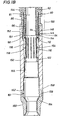
- Figure 1 is an elevational view in partial section of the zone isolation system of the present invention wherein fluid is allowed to pass into the well bore;
- Figure 2 is a perspective view of the shifting collet;
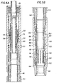
- Figure 3 is an elevational view in partial section of the initial movement of the shifting collet assembly through the shifting collet housing assembly;
- Figure 4 is an elevational view in partial section of the further movement of the shifting collet assembly through the shifting collet housing assembly;
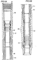
- Figure 5 is an elevational view in partial section of the zone isolation system in a second position wherein the flow fluid through the sand control production screen is prevented from flowing back the well bore; and
- Figure 6 is an elevational view in partial section of the zone isolation system with the shifting collet assembly removed therefrom.
- A still further understanding of the construction and operation of the
zone isolation system 10 of the present invention may be had by reference to the following discussion of the preferred embodiment as illustrated in the accompanying drawing figures. - In Figure 1, the
zone isolation system 10 of the present invention is shown positioned within aproduction piping assembly 12. Theproduction piping assembly 12 includes an upper polished bore receptacle orPBR 130 which is connected byexternal threads 134 at itsdistal end 132 tointernal threads 136 in theproximal end 138 of acollar 135. Thedistal end 139 of thecollar 135 is connected byinternal threads 137 toexternal threads 141 located on theproximal end 142 of a blank pipe andscreen assembly 140. The blank pipe andscreen assembly 140 is in turn threadably connected byexternal threads 145 on itsdistal end 146 tointernal threads 151 on theproximal end 152 on alower PBR 150. Thedistal end 158 of thelower PBR 150 is connected byexternal threads 159 tointernal threads 161 located on theproximal end 162 of abottom sub 160. - At the proximal end of the
production piping assembly 12 is located awashpipe 22, atop sub 30 and a shiftingcollet assembly 40. Thedistal end 21 of thewash pipe 22 is connected byexternal threads 26 tointernal threads 31 located on theproximal end 32 of thetop sub 30. Thedistal end 36 of thetop sub 30 is connected byinternal threads 38 toexternal threads 44 formed on theproximal end 43 of amandrel 42. Themandrel 42 carries the shiftingcollet 45 on itsexterior surface 41. If desired, holes or slots 50 (shown only in Figure 1) may be formed through themandrel 42 to prevent the buildup of sand in the space between the bottom of the flexible beam portions 51 (Figure 2) and theexterior surface 41 of themandrel 42. - The shifting
collet 45 itself is shown in Figure 2. It includes aninterior bore 46 for housing themandrel 42. Formed on theexterior surface 48 are a plurality ofproximal projections 52 and a plurality ofdistal projections 56. Theproximal projections 52 includes aramp 53 and ashoulder 54. Similarly, thedistal projections 56 include aramp 57 and ashoulder 58.Slots 49 are formed in the shiftingcollet 45 so that theprojections flexible beam 51 anchored at thesolid portions 59 either end of the shiftingcollet 45. The utilization of theflexible beam 51 portion of the shiftingcollet 45 will be explained below. - As shown by reference to Figure 3 and to Figure 4, the shifting
collet assembly 40 is sized to fit within a shiftingcollet housing assembly 60. Located on theexterior 61 of the shiftingcollet housing assembly 60 are a pair of O-rings 76 which form a proximalfluid seal assembly 77 against the interior 131 (Figure 5) of theupper PBR 130. Alternatively, bonded seals as explained below in the description of thelower collet assembly 110 may be used. - By reference back to Figure 1, it may be seen that the
distal end 78 of the shiftingcollet housing assembly 60 is threadably connected to theinternal threads 84 formed on theproximal end 82 of the isolationpipe string assembly 80. Theexternal threads 88 on thedistal end 86 of the isolationpipe string assembly 80 are threadably connected to theinternal threads 94 formed on theproximal end 92 of aseal sub 90. Surrounding theseal sub 90 at itsdistal end 96 is adistal seal 100 which forms a fluid seal against theinterior surface 155 of thelower PBR 150. - Connected to the
external threads 98 formed on thedistal end 96 of theseal sub 90 are theinternal threads 114 formed on theproximal end 112 of alower collet assembly 110. Thelower collet assembly 110 includesslots 116 through which fluids passing through the sandcontrol production screen 144 may flow. - By further reference to Figure 1, the flow path for fluids will be through sand
control production screen 144, thence through theannulus 143 between the blank pipe andproduction screen assembly 140 and the isolationpipe string assembly 80, past thedistal seal 100 and through theslots 116 in thelower collet assembly 110 and then upward through the interior bore 81 of the isolationpipe string assembly 80, through the interior bore 47 of themandrel 42, through thetop sub 30 and finally through thewash pipe 22. Travel of fluid through theannulus 143 between the isolationpipe string assembly 80 and the blank pipe andscreen assembly 140 is prevented by the proximal fluid seal 77 (Figure 3) between the shiftingcollet housing assembly 60 and theupper PBR 130. - When it is desired to prevent the flow of fluid through the interior 81 of the isolation
pipe string assembly 80 it is necessary to move the isolationpipe string assembly 80 into a lower or more distal position within the well bore 24. As may be seen in Figure 5, this lower or more distal position maintains the barrier to fluid flow formed by theproximal fluid seal 77 between the shiftingcollet housing assembly 60 and theinner bore 131 of theupper PBR 130. Thedistal seal 100 established by sealing contact between theseal assembly 100 and theinner bore 155 of thelower PBR 150 prevents fluid flow through thelower collet assembly 110. Thisdistal seal 100 is established by a pair of bondedseals ring seals screen 144 it is blocked from traveling upward through the well bore 24 by the proximalfluid seal assembly 77 formed against the interior bore 131 of theupper PBR 130 and it is blocked from traveling through theslots 116 in thelower collet assembly 110 by the distalfluid seal assembly 100 formed against theinterior wall 155 of thelower PBR 150. - The movement of the isolation
pipe string assembly 80 to its second or more distal position within the well bore 24 is a two stroke operation as shown in Figures 3, 4 and 5. First, the shiftingcollet assembly 40 is pulled upwardly through the isolationpipe string assembly 80 and through the shiftingcollet housing assembly 60. Such withdrawal of the shiftingcollet assembly 40 through the shiftingcollet housing assembly 60 causes theramps distal projections 56 emanating from theside 48 of the shifting collet 45 (Figure 2) to slide past theramp 71 formed on the bottom of the slidingrelease sleeve 72 and past theramp 65 formed on the bottom of theentry guide 64. - Once the shifting
collet assembly 40 has been pulled through the shiftingcollet housing assembly 60, it is reinserted into the shifting collet housing assembly as shown in Figure 3. It is at this time that any repairs or adjustments to the service tool, the production pipeline or any of the packing assemblies may be made. This reinsertion of the shiftingcollet assembly 40 into the shiftingcollet housing assembly 60 causes theproximal projections 52 on theexterior surface 48 of the shiftingcollet 45 to enter therecess 74 in the center portion of the slidingrelease sleeve 72. Theshoulders 54 on the bottom of theproximal projections 52 push against the bottom of therecess 74 and severs theshear screw 69 which, by threadable engagement withhole 70 has held the slidingrelease sleeve 72 in a proximal position with respect to the shiftingcollet housing assembly 60 as shown in Figure 1. - The movement of the sliding
release sleeve 72 after theshear screw 69 has been severed, as shown in Figure 3, accomplishes two things. First, thesnap ring 68 collapses inward as it no longer is held in its distended position by the proximal location of the sliding release sleeve 72 (Figure 1). The collapsed position of thesnap ring 68 prevents upward movement of the slidingrelease sleeve 72 back through the shiftingcollet housing assembly 60. Second, as shown in Figure 4, thebottom shoulder 75 of the slidingrelease sleeve 72 engages ashoulder 67 formed within the shiftingcollet housing assembly 60. The shiftingcollet 45 continues to pass through the shiftingcollet housing assembly 60. Theshoulders 58 on thedistal projections 56 of theexterior surface 48 of the shiftingcollet 45 ride downramp 62. This movement causes a downward movement of theflex beam 51 portion of the shiftingcollet 45 which draws theproximal projections 52 out of therecess 74 formed in the slidingrelease sleeve 72. Further travel of the shiftingcollet assembly 40 through the shiftingcollet housing assembly 60 will cause theshoulders 54 on theproximal projections 56 to move alongramp 62. - Once the shifting
collet assembly 40 has passed through the shifting collet housing assembly 60 a first time, the shiftingcollet assembly 40 is withdrawn back through the shiftingcollet housing assembly 60. The shiftingcollet assembly 40 is now caused to enter the shifting collet housing assembly 60 a second time. This re-entry of the shiftingcollet assembly 40 into the shiftingcollet housing assembly 60 is shown in Figure 5. Theshoulder 58 on the bottom of thedistal projection 56 engages theshoulder 73 on top of the slidingrelease sleeve 72. Continued downward force by theshoulder 58 on thedistal projection 56 against theshoulder 73 on top of the slidingrelease sleeve 72 will cause the entire isolationpipe string assembly 80 to move to the distal end of the well bore 24. - As may be seen by comparing Figure 1 to Figure 5, the downward movement of the isolation
pipe string assembly 80 within the well bore 24 can only be accomplished if theprojection 118 on the exterior of thelower collet assembly 110 is moved out of engagement withproximal recess 154 formed withinlower PBR 150. Such movement will allow thedistal seal assembly 100 to move from within the blank pipe andscreen assembly 140 to a position wherein sealing contact is formed against theinterior wall 155 of thelower PBR 150. Once the isolationpipe string assembly 80 is moved by the force ofshoulder 58 againstshoulder 73 theprojection 118 will move inward to slide along theinterior 155 of thelower PBR 150 and then move outward to enter thedistal recess 156 formed on thedistal end 158 of thelower PBR 150. Thedistal end 122 of thelower collet assembly 110 will come to rest against aslant shoulder 164 formed within the bore of theproximal end 162 of thebottom sub 160. - By reference to Figure 6 there is nothing to retain the shifting
collet assembly 40 within the shiftingcollet housing assembly 60, thus it may be easily removed as previously described. Passage of fluids from the formation surrounding the well bore 24 is accomplished by perforating the isolationpipe string assembly 80 or alternatively moving a sliding sleeve (not shown) which covers an opening formed in the isolationpipe string assembly 80. - The
zone isolation system 10 of the present invention is assembled by threadably connecting thelower PBR 150 to the blank pipe andscreen assembly 140. Next, thelower collet assembly 110 is threadably connected to theseal sub 90 which includes thedistal seal assembly 100. - Next the
lower collet assembly 110 is inserted into thelower PBR 150 so that theprojection 118 on the exterior of thelower collet assembly 110 engages theproximal recess 154 after sliding along the entry ramp 153 (Figure 5) formed on theproximal end 152 of thelower PBR 150. The shiftingcollet assembly 40 is then slid through the shiftingcollet housing assembly 60 so that theproximal projections 52 and thedistal projections 56 on theexterior 48 of the shiftingcollet assembly 40 enters the interior bore 81 of the isolationpipe string assembly 80. The shiftingcollet housing assembly 60 is then attached to the top of theisolation pipe assembly 80. Thewash pipe 22 is then threadably attached to thetop sub 30. Finally, theupper PBR 130 is threadably attached to the blank pipeend screen assembly 140. - When it is desired to activate the
zone isolation system 10 of the present invention to move the isolationpipe string assembly 80 further into the well bore 24 a service tool (not shown) is connected to thewash pipe 22 to pull the shiftingcollet assembly 40 out of the shiftingcollet housing assembly 60 so that the bottom of the shiftingcollet assembly 40 clears the top of the shiftingcollet housing assembly 60. - The next step is to apply a set-down weight on the shifting
collet assembly 40. Because thedistal projection 56 on the exterior of the shiftingcollet 45 is larger than theproximal projection 52, it slides past therecess 74 in the slidingrelease sleeve 72. When theproximal projections 52, which are sized to enter therecess 74 in the sliding release sleeve, thebeam 51 flexes outward. This outward flexing of thebeam 51 causes theshoulders 54 on theproximal projections 52 on the shiftingcollet assembly 45 to engage the bottom of therecess 74 in the slidingrelease sleeve 72. As previously indicated this causes theshear screw 69 to sever and the slidingrelease sleeve 72 to move downward into contact with ashoulder 67 within the shiftingcollet housing assembly 60. Thesnap ring 68 is now free to move inward to block the upward travel of the shiftingrelease sleeve 72. The inward flexing of thebeam portions 51 of the shiftingcollet 45 cause theproximal projections 52 to move out of therecess 73. This completes the first entry of the shiftingcollet assembly 40 into the shiftingcollet housing assembly 60. - The closing off the sand
control production screen 144 from the flow of fluid is accomplished by moving thedistal seal 100 into contact with theinterior surface 155 of thelower PBR 150. This movement is accomplished by a second insertion of the shiftingcollet assembly 40 into the shiftingcollet housing assembly 60. Theshoulders 58 on thedistal projections 56 engage the top of the slidingrelease sleeve 72 which causes the bottom of the slidingrelease sleeve 72 to push against ashoulder 67 formed within the shiftingcollet housing assembly 60. The area of surface engagement is sufficient to apply enough force on the shiftingcollet housing assembly 60 to move theprojections 118 on thelower collet assembly 110 inward so that they may travel along theinner bore 155 of thelower PBR 150 before moving outward intorecess 156. Because there are no threadable connections between the shiftingcollet assembly 40 and the shiftingcollet housing assembly 60, the shiftingcollet assembly 40 may be easily withdrawn back through the shiftingcollet housing assembly 60. The isolationpipe string assembly 80 is now in place behind the sandcontrol production screen 144 with theproximal seal 77 blocking the upward passage of fluid and thedistal seal 100 blocking the downward passage of fluid. - As the
zone isolation system 10 of the present invention has now been explained by reference to its preferred embodiment, it will be understood by those of ordinary skill in the art that other embodiments incorporating the same principles of construction and operation as found in the instant invention may be fabricated by those of ordinary skill in the art. Such other embodiments shall be included within the scope and meaning of the appended claims.
Claims (17)
- A zone isolation system (10) for use with a production pipe assembly (12), said zone isolation system (10) comprising:characterized in that said isolation pipe string assembly (80) includes:a substantially cylindrical sand control production screen (144);an isolation pipe string assembly (80) constructed and arranged to be movable within said substantially cylindrical sand control production screen (144); andwhereby in a first proximal position of said isolation pipe string assembly (80) with respect to the production pipe assembly (12), said proximal fluid seal (77) is in contact with the interior of said production pipe assembly (12), said distal fluid seal (100) is out of contact with the interior of said production pipe assembly (12), and fluid may travel through said lower slotted section (116) into the interior of said production pipe assembly (12); anda proximal fluid seal (77);a distal fluid seal (100);a lower slotted section (116) below said distal fluid seal (100); anda shifting collet assembly (40) constructed and arranged to be movable within said isolation pipe string assembly (80);
whereby said shifting collet assembly (40) is constructed and arranged to interact with the interior of said isolation pipe string assembly (80) to move said isolation pipe string assembly (80) into a second distal position with respect to the production pipe assembly (12) in which said proximal fluid seal (77) is in contact with the interior of said production pipe assembly (12) and said distal fluid seal (100) is in contact with the interior of said production pipe assembly (12) and fluid is prevented from traveling through said lower slotted section (116). - A zone isolation system (10) as claimed in claim 1, wherein said isolation pipe string assembly (80) includes a shifting collet housing assembly (60).
- A zone isolation system (10) as claimed in claim 2, wherein said shifting collet housing assembly (60) further includes a sliding release sleeve (72).
- A zone isolation system (10) as claimed in claim 3, wherein said shifting collet assembly (40) includes a projection (56) constructed and arranged to engage and move said sliding release sleeve (72).
- A zone isolation system (10) as claimed in claim 4, wherein said shifting collet housing assembly (60) includes a shoulder (58) engageable by said sliding release sleeve (72).
- A zone isolation system (10) as claimed in any preceding claim, wherein said shifting collet assembly (40) includes a shifting collet (45) and a mandrel (42) constructed and arranged to pass through said shifting collet assembly (40).
- A zone isolation system (10) as claimed in claim 6, wherein said shifting collet (45) further includes a plurality of flex beam portions (51) anchored to its ends.
- A zone isolation system (10) as claimed in claim 6 or 7, wherein the wall of the mandrel (42) includes holes (50) formed therethrough.
- A method for isolating a production pipe assembly (12) in a well bore from re-entry of fluids through a sand control production screen (144) comprising:(a) attaching a shifting collet housing assembly (60) to an isolation pipe string assembly (80);(b) inserting said isolation pipe string assembly (80) having said shifting collet housing assembly (60) into the production pipe assembly (12);(c) inserting a shifting collet assembly (40) so that said shifting collet assembly (40) engages the interior of said shining collet housing assembly (60);(d) imparting a downward force on said shifting collet assembly (40) to move said isolation pipe string assembly (80) into a position wherein said isolation pipe string assembly (80) is in sealing contact with the production pipe assembly (12) both above and below said sand control production screen (144).
- A method as claimed in claim 9, wherein said step (c) further includes moving a sliding release sleeve (72) toward the distal end of said shifting collet housing assembly (60).
- A method as claimed in claim 10, further including the step of retaining said sliding release sleeve (72) in place following its movement to the distal end of said shifting collet housing assembly (60).
- A method as claimed in claim 11, wherein the retention of said sliding release sleeve (72) in place is accomplished by the collapsing of a snap ring (68).
- A method as claimed in claim 10, 11 or 12, wherein said downward force on said shifting collet assembly (40) is transferred to said sliding release sleeve (72) within said shifting collet housing assembly (60).
- A method as claimed in any of claims claim 9 - 13, wherein said shifting collet assembly (40) is drawn back through said shifting collet housing assembly (60) prior to the commencement of step (d).
- A method as claimed in claim 14, wherein said downward force is applied to a sliding release sleeve (72) within the shifting collet assembly (40) and transferred thereby to said shifting collet housing assembly (60) to cause the movement of said isolation pipe string assembly (80).
- A method for converting a non-isolated production pipe assembly into an isolated production pipe assembly comprising:thereby converting said non-isolated production pipe (12) assembly into said isolated production pipe assembly, wherein said isolated production pipe assembly in the well bore is isolated from re-entry of fluids through said sand control production screen (144).(a) providing a non-isolated production pipe (12) assembly in a well bore, said non-isolated production pipe assembly (12) having a sand control production screen (144);(b) attaching a shifting collet housing assembly (60) to an isolation pipe string assembly (80);(c) inserting said isolation pipe string assembly (80) having the shifting collet housing assembly (60) attached thereto into said non-isolated production pipe assembly (12);(d) inserting a shifting collet assembly (40) so that said shifting collet assembly (40) engages the interior of said shifting collet housing assembly (60); and(e) imparting a downward force on said shifting collet assembly (40) to move said isolation pipe string assembly (80) into a position wherein said isolation pipe string assembly (80) is in sealing contact with the non-isolated production pipe assembly (12) both above and below said sand control production screen (144); and
- A method as claimed in claim 16, further comprising:wherein said downward force is applied to a sliding release sleeve (72) within the shifting collet assembly (40) and transferred thereby to said shifting collet housing assembly (60) to cause the movement of said isolation pipe string assembly (80).(f) drawing said shifting collet assembly (40) back through said shifting collet housing assembly (60) prior to the commencement of step (e),
Applications Claiming Priority (2)
| Application Number | Priority Date | Filing Date | Title |
|---|---|---|---|
| US918213 | 1997-08-25 | ||
| US08/918,213 US5988285A (en) | 1997-08-25 | 1997-08-25 | Zone isolation system |
Publications (3)
| Publication Number | Publication Date |
|---|---|
| EP0899419A2 EP0899419A2 (en) | 1999-03-03 |
| EP0899419A3 EP0899419A3 (en) | 2002-01-23 |
| EP0899419B1 true EP0899419B1 (en) | 2004-02-25 |
Family
ID=25439994
Family Applications (1)
| Application Number | Title | Priority Date | Filing Date |
|---|---|---|---|
| EP98202783A Expired - Lifetime EP0899419B1 (en) | 1997-08-25 | 1998-08-19 | System and method for isolating a zone in a borehole |
Country Status (3)
| Country | Link |
|---|---|
| US (1) | US5988285A (en) |
| EP (1) | EP0899419B1 (en) |
| DE (1) | DE69821841D1 (en) |
Families Citing this family (54)
| Publication number | Priority date | Publication date | Assignee | Title |
|---|---|---|---|---|
| US6302208B1 (en) * | 1998-05-15 | 2001-10-16 | David Joseph Walker | Gravel pack isolation system |
| US6253853B1 (en) * | 1998-10-05 | 2001-07-03 | Stellarton Energy Corporation | Fluid injection tubing assembly and method |
| US6695057B2 (en) * | 2001-05-15 | 2004-02-24 | Weatherford/Lamb, Inc. | Fracturing port collar for wellbore pack-off system, and method for using same |
| US6253856B1 (en) | 1999-11-06 | 2001-07-03 | Weatherford/Lamb, Inc. | Pack-off system |
| US6513595B1 (en) * | 2000-06-09 | 2003-02-04 | Weatherford/Lamb, Inc. | Port collar assembly for use in a wellbore |
| US7100690B2 (en) * | 2000-07-13 | 2006-09-05 | Halliburton Energy Services, Inc. | Gravel packing apparatus having an integrated sensor and method for use of same |
| US6575243B2 (en) * | 2001-04-16 | 2003-06-10 | Schlumberger Technology Corporation | Zonal isolation tool with same trip pressure test |
| US6494256B1 (en) | 2001-08-03 | 2002-12-17 | Schlumberger Technology Corporation | Apparatus and method for zonal isolation |
| US6719051B2 (en) | 2002-01-25 | 2004-04-13 | Halliburton Energy Services, Inc. | Sand control screen assembly and treatment method using the same |
| US6899176B2 (en) | 2002-01-25 | 2005-05-31 | Halliburton Energy Services, Inc. | Sand control screen assembly and treatment method using the same |
| US7096945B2 (en) * | 2002-01-25 | 2006-08-29 | Halliburton Energy Services, Inc. | Sand control screen assembly and treatment method using the same |
| US7055598B2 (en) * | 2002-08-26 | 2006-06-06 | Halliburton Energy Services, Inc. | Fluid flow control device and method for use of same |
| US6814139B2 (en) * | 2002-10-17 | 2004-11-09 | Halliburton Energy Services, Inc. | Gravel packing apparatus having an integrated joint connection and method for use of same |
| CN100453770C (en) * | 2002-12-23 | 2009-01-21 | 北京海能海特石油科技发展有限公司 | Screens with Flow Regulators |
| US6857476B2 (en) | 2003-01-15 | 2005-02-22 | Halliburton Energy Services, Inc. | Sand control screen assembly having an internal seal element and treatment method using the same |
| US6886634B2 (en) * | 2003-01-15 | 2005-05-03 | Halliburton Energy Services, Inc. | Sand control screen assembly having an internal isolation member and treatment method using the same |
| US6978840B2 (en) * | 2003-02-05 | 2005-12-27 | Halliburton Energy Services, Inc. | Well screen assembly and system with controllable variable flow area and method of using same for oil well fluid production |
| US6994170B2 (en) * | 2003-05-29 | 2006-02-07 | Halliburton Energy Services, Inc. | Expandable sand control screen assembly having fluid flow control capabilities and method for use of same |
| US7140437B2 (en) * | 2003-07-21 | 2006-11-28 | Halliburton Energy Services, Inc. | Apparatus and method for monitoring a treatment process in a production interval |
| US7191833B2 (en) * | 2004-08-24 | 2007-03-20 | Halliburton Energy Services, Inc. | Sand control screen assembly having fluid loss control capability and method for use of same |
| US7387165B2 (en) * | 2004-12-14 | 2008-06-17 | Schlumberger Technology Corporation | System for completing multiple well intervals |
| US7322417B2 (en) * | 2004-12-14 | 2008-01-29 | Schlumberger Technology Corporation | Technique and apparatus for completing multiple zones |
| US8505632B2 (en) | 2004-12-14 | 2013-08-13 | Schlumberger Technology Corporation | Method and apparatus for deploying and using self-locating downhole devices |
| US8056628B2 (en) | 2006-12-04 | 2011-11-15 | Schlumberger Technology Corporation | System and method for facilitating downhole operations |
| US8245782B2 (en) | 2007-01-07 | 2012-08-21 | Schlumberger Technology Corporation | Tool and method of performing rigless sand control in multiple zones |
| US20080283252A1 (en) * | 2007-05-14 | 2008-11-20 | Schlumberger Technology Corporation | System and method for multi-zone well treatment |
| US7918276B2 (en) * | 2007-06-20 | 2011-04-05 | Schlumberger Technology Corporation | System and method for creating a gravel pack |
| US7730949B2 (en) * | 2007-09-20 | 2010-06-08 | Schlumberger Technology Corporation | System and method for performing well treatments |
| US8511380B2 (en) * | 2007-10-10 | 2013-08-20 | Schlumberger Technology Corporation | Multi-zone gravel pack system with pipe coupling and integrated valve |
| US7624810B2 (en) * | 2007-12-21 | 2009-12-01 | Schlumberger Technology Corporation | Ball dropping assembly and technique for use in a well |
| US8096356B2 (en) * | 2008-01-25 | 2012-01-17 | Schlumberger Technology Corporation | System and method for preventing buckling during a gravel packing operation |
| US8002040B2 (en) * | 2008-04-23 | 2011-08-23 | Schlumberger Technology Corporation | System and method for controlling flow in a wellbore |
| WO2009148723A1 (en) * | 2008-06-04 | 2009-12-10 | Exxonmobil Upstream Research Company | Inter and intra-reservoir flow controls |
| US8496055B2 (en) * | 2008-12-30 | 2013-07-30 | Schlumberger Technology Corporation | Efficient single trip gravel pack service tool |
| US8371389B2 (en) * | 2010-03-17 | 2013-02-12 | Summit Downhole Dynamics, Ltd | Differential shifting tool and method of shifting |
| US9382790B2 (en) | 2010-12-29 | 2016-07-05 | Schlumberger Technology Corporation | Method and apparatus for completing a multi-stage well |
| US9371479B2 (en) | 2011-03-16 | 2016-06-21 | Schlumberger Technology Corporation | Controlled release biocides in oilfield applications |
| US8944171B2 (en) | 2011-06-29 | 2015-02-03 | Schlumberger Technology Corporation | Method and apparatus for completing a multi-stage well |
| US9752407B2 (en) | 2011-09-13 | 2017-09-05 | Schlumberger Technology Corporation | Expandable downhole seat assembly |
| US10364629B2 (en) | 2011-09-13 | 2019-07-30 | Schlumberger Technology Corporation | Downhole component having dissolvable components |
| US9033041B2 (en) | 2011-09-13 | 2015-05-19 | Schlumberger Technology Corporation | Completing a multi-stage well |
| US9534471B2 (en) | 2011-09-30 | 2017-01-03 | Schlumberger Technology Corporation | Multizone treatment system |
| US9394752B2 (en) | 2011-11-08 | 2016-07-19 | Schlumberger Technology Corporation | Completion method for stimulation of multiple intervals |
| US9238953B2 (en) | 2011-11-08 | 2016-01-19 | Schlumberger Technology Corporation | Completion method for stimulation of multiple intervals |
| US9279306B2 (en) | 2012-01-11 | 2016-03-08 | Schlumberger Technology Corporation | Performing multi-stage well operations |
| US8844637B2 (en) | 2012-01-11 | 2014-09-30 | Schlumberger Technology Corporation | Treatment system for multiple zones |
| US9650851B2 (en) | 2012-06-18 | 2017-05-16 | Schlumberger Technology Corporation | Autonomous untethered well object |
| US9528336B2 (en) | 2013-02-01 | 2016-12-27 | Schlumberger Technology Corporation | Deploying an expandable downhole seat assembly |
| US9631468B2 (en) | 2013-09-03 | 2017-04-25 | Schlumberger Technology Corporation | Well treatment |
| US9587477B2 (en) | 2013-09-03 | 2017-03-07 | Schlumberger Technology Corporation | Well treatment with untethered and/or autonomous device |
| US10487625B2 (en) | 2013-09-18 | 2019-11-26 | Schlumberger Technology Corporation | Segmented ring assembly |
| US9644452B2 (en) | 2013-10-10 | 2017-05-09 | Schlumberger Technology Corporation | Segmented seat assembly |
| CA2996174A1 (en) | 2015-08-21 | 2017-03-02 | Schlumberger Canada Limited | Environmentally acceptable surfactant in aqueous-based stimulation fluids |
| US10538988B2 (en) | 2016-05-31 | 2020-01-21 | Schlumberger Technology Corporation | Expandable downhole seat assembly |
Family Cites Families (5)
| Publication number | Priority date | Publication date | Assignee | Title |
|---|---|---|---|---|
| US4401158A (en) * | 1980-07-21 | 1983-08-30 | Baker International Corporation | One trip multi-zone gravel packing apparatus |
| US4858690A (en) * | 1988-07-27 | 1989-08-22 | Completion Services, Inc. | Upward movement only actuated gravel pack system |
| US5333688A (en) * | 1993-01-07 | 1994-08-02 | Mobil Oil Corporation | Method and apparatus for gravel packing of wells |
| US5609204A (en) * | 1995-01-05 | 1997-03-11 | Osca, Inc. | Isolation system and gravel pack assembly |
| US5579844A (en) * | 1995-02-13 | 1996-12-03 | Osca, Inc. | Single trip open hole well completion system and method |
-
1997
- 1997-08-25 US US08/918,213 patent/US5988285A/en not_active Expired - Lifetime
-
1998
- 1998-08-19 DE DE69821841T patent/DE69821841D1/en not_active Expired - Lifetime
- 1998-08-19 EP EP98202783A patent/EP0899419B1/en not_active Expired - Lifetime
Also Published As
| Publication number | Publication date |
|---|---|
| EP0899419A2 (en) | 1999-03-03 |
| US5988285A (en) | 1999-11-23 |
| EP0899419A3 (en) | 2002-01-23 |
| DE69821841D1 (en) | 2004-04-01 |
Similar Documents
| Publication | Publication Date | Title |
|---|---|---|
| EP0899419B1 (en) | System and method for isolating a zone in a borehole | |
| US6575243B2 (en) | Zonal isolation tool with same trip pressure test | |
| US6769490B2 (en) | Downhole surge reduction method and apparatus | |
| EP0430389B1 (en) | Gravel packing assembly | |
| US5871050A (en) | Well completion method | |
| US5180016A (en) | Apparatus and method for placing and for backwashing well filtration devices in uncased well bores | |
| CA2444005C (en) | Disconnect for use in a wellbore | |
| US5865251A (en) | Isolation system and gravel pack assembly and uses thereof | |
| US5810084A (en) | Gravel pack apparatus | |
| US7798212B2 (en) | System and method for forming downhole connections | |
| US6302208B1 (en) | Gravel pack isolation system | |
| US6378609B1 (en) | Universal washdown system for gravel packing and fracturing | |
| US7980311B2 (en) | Devices, systems and methods for equalizing pressure in a gas well | |
| JPS6236119B2 (en) | ||
| US11542795B2 (en) | Mechanical isolation plugs for inflow control devices | |
| EP0424452B1 (en) | Plug for well logging operations | |
| GB2280462A (en) | Setting apparatus | |
| US3990510A (en) | Releasable well anchor tool | |
| US4655298A (en) | Annulus pressure firer mechanism with releasable fluid conduit force transmission means | |
| US6978844B2 (en) | Filling and circulating apparatus for subsurface exploration | |
| US5732775A (en) | Multiple casing segment cementing system | |
| US4105074A (en) | Cementing staging tool | |
| US7198109B2 (en) | Double-pin radial flow valve | |
| US5219025A (en) | Method and apparatus for gravel packing a well through a tubing string | |
| US3827491A (en) | Apparatus for selectively receiving and releasing well tools |
Legal Events
| Date | Code | Title | Description |
|---|---|---|---|
| PUAI | Public reference made under article 153(3) epc to a published international application that has entered the european phase |
Free format text: ORIGINAL CODE: 0009012 |
|
| AK | Designated contracting states |
Kind code of ref document: A2 Designated state(s): AT BE CH CY DE DK ES FI FR GB GR IE IT LI LU MC NL PT SE Kind code of ref document: A2 Designated state(s): DE DK FR GB IT NL |
|
| AX | Request for extension of the european patent |
Free format text: AL;LT;LV;MK;RO;SI |
|
| PUAL | Search report despatched |
Free format text: ORIGINAL CODE: 0009013 |
|
| AK | Designated contracting states |
Kind code of ref document: A3 Designated state(s): AT BE CH CY DE DK ES FI FR GB GR IE IT LI LU MC NL PT SE |
|
| AX | Request for extension of the european patent |
Free format text: AL;LT;LV;MK;RO;SI |
|
| 17P | Request for examination filed |
Effective date: 20020405 |
|
| AKX | Designation fees paid |
Free format text: DE DK FR GB IT NL |
|
| 17Q | First examination report despatched |
Effective date: 20011022 |
|
| GRAP | Despatch of communication of intention to grant a patent |
Free format text: ORIGINAL CODE: EPIDOSNIGR1 |
|
| GRAS | Grant fee paid |
Free format text: ORIGINAL CODE: EPIDOSNIGR3 |
|
| GRAA | (expected) grant |
Free format text: ORIGINAL CODE: 0009210 |
|
| AK | Designated contracting states |
Kind code of ref document: B1 Designated state(s): DE DK FR GB IT NL |
|
| PG25 | Lapsed in a contracting state [announced via postgrant information from national office to epo] |
Ref country code: NL Free format text: LAPSE BECAUSE OF FAILURE TO SUBMIT A TRANSLATION OF THE DESCRIPTION OR TO PAY THE FEE WITHIN THE PRESCRIBED TIME-LIMIT Effective date: 20040225 Ref country code: IT Free format text: LAPSE BECAUSE OF FAILURE TO SUBMIT A TRANSLATION OF THE DESCRIPTION OR TO PAY THE FEE WITHIN THE PRESCRIBED TIME-LIMIT;WARNING: LAPSES OF ITALIAN PATENTS WITH EFFECTIVE DATE BEFORE 2007 MAY HAVE OCCURRED AT ANY TIME BEFORE 2007. THE CORRECT EFFECTIVE DATE MAY BE DIFFERENT FROM THE ONE RECORDED. Effective date: 20040225 |
|
| REG | Reference to a national code |
Ref country code: GB Ref legal event code: FG4D |
|
| REG | Reference to a national code |
Ref country code: IE Ref legal event code: FG4D |
|
| REF | Corresponds to: |
Ref document number: 69821841 Country of ref document: DE Date of ref document: 20040401 Kind code of ref document: P |
|
| PG25 | Lapsed in a contracting state [announced via postgrant information from national office to epo] |
Ref country code: DK Free format text: LAPSE BECAUSE OF FAILURE TO SUBMIT A TRANSLATION OF THE DESCRIPTION OR TO PAY THE FEE WITHIN THE PRESCRIBED TIME-LIMIT Effective date: 20040525 |
|
| PG25 | Lapsed in a contracting state [announced via postgrant information from national office to epo] |
Ref country code: DE Free format text: LAPSE BECAUSE OF FAILURE TO SUBMIT A TRANSLATION OF THE DESCRIPTION OR TO PAY THE FEE WITHIN THE PRESCRIBED TIME-LIMIT Effective date: 20040526 |
|
| NLV1 | Nl: lapsed or annulled due to failure to fulfill the requirements of art. 29p and 29m of the patents act | ||
| ET | Fr: translation filed | ||
| PLBE | No opposition filed within time limit |
Free format text: ORIGINAL CODE: 0009261 |
|
| STAA | Information on the status of an ep patent application or granted ep patent |
Free format text: STATUS: NO OPPOSITION FILED WITHIN TIME LIMIT |
|
| 26N | No opposition filed |
Effective date: 20041126 |
|
| REG | Reference to a national code |
Ref country code: IE Ref legal event code: MM4A |
|
| PGFP | Annual fee paid to national office [announced via postgrant information from national office to epo] |
Ref country code: GB Payment date: 20070815 Year of fee payment: 10 |
|
| PGFP | Annual fee paid to national office [announced via postgrant information from national office to epo] |
Ref country code: FR Payment date: 20070808 Year of fee payment: 10 |
|
| GBPC | Gb: european patent ceased through non-payment of renewal fee |
Effective date: 20080819 |
|
| REG | Reference to a national code |
Ref country code: FR Ref legal event code: ST Effective date: 20090430 |
|
| PG25 | Lapsed in a contracting state [announced via postgrant information from national office to epo] |
Ref country code: FR Free format text: LAPSE BECAUSE OF NON-PAYMENT OF DUE FEES Effective date: 20080901 |
|
| PG25 | Lapsed in a contracting state [announced via postgrant information from national office to epo] |
Ref country code: GB Free format text: LAPSE BECAUSE OF NON-PAYMENT OF DUE FEES Effective date: 20080819 |