EP0899073A2 - Process for manufacturing an air flow valve - Google Patents
Process for manufacturing an air flow valve Download PDFInfo
- Publication number
- EP0899073A2 EP0899073A2 EP98114874A EP98114874A EP0899073A2 EP 0899073 A2 EP0899073 A2 EP 0899073A2 EP 98114874 A EP98114874 A EP 98114874A EP 98114874 A EP98114874 A EP 98114874A EP 0899073 A2 EP0899073 A2 EP 0899073A2
- Authority
- EP
- European Patent Office
- Prior art keywords
- disc
- bore
- shaft
- process according
- throttle body
- Prior art date
- Legal status (The legal status is an assumption and is not a legal conclusion. Google has not performed a legal analysis and makes no representation as to the accuracy of the status listed.)
- Granted
Links
Images


Classifications
-
- B—PERFORMING OPERATIONS; TRANSPORTING
- B29—WORKING OF PLASTICS; WORKING OF SUBSTANCES IN A PLASTIC STATE IN GENERAL
- B29C—SHAPING OR JOINING OF PLASTICS; SHAPING OF MATERIAL IN A PLASTIC STATE, NOT OTHERWISE PROVIDED FOR; AFTER-TREATMENT OF THE SHAPED PRODUCTS, e.g. REPAIRING
- B29C65/00—Joining or sealing of preformed parts, e.g. welding of plastics materials; Apparatus therefor
- B29C65/56—Joining or sealing of preformed parts, e.g. welding of plastics materials; Apparatus therefor using mechanical means or mechanical connections, e.g. form-fits
- B29C65/60—Riveting or staking
- B29C65/606—Riveting or staking the rivets being integral with one of the parts to be joined, i.e. staking
-
- B—PERFORMING OPERATIONS; TRANSPORTING
- B29—WORKING OF PLASTICS; WORKING OF SUBSTANCES IN A PLASTIC STATE IN GENERAL
- B29C—SHAPING OR JOINING OF PLASTICS; SHAPING OF MATERIAL IN A PLASTIC STATE, NOT OTHERWISE PROVIDED FOR; AFTER-TREATMENT OF THE SHAPED PRODUCTS, e.g. REPAIRING
- B29C35/00—Heating, cooling or curing, e.g. crosslinking or vulcanising; Apparatus therefor
- B29C35/02—Heating or curing, e.g. crosslinking or vulcanizing during moulding, e.g. in a mould
- B29C35/08—Heating or curing, e.g. crosslinking or vulcanizing during moulding, e.g. in a mould by wave energy or particle radiation
- B29C35/0805—Heating or curing, e.g. crosslinking or vulcanizing during moulding, e.g. in a mould by wave energy or particle radiation using electromagnetic radiation
-
- B—PERFORMING OPERATIONS; TRANSPORTING
- B29—WORKING OF PLASTICS; WORKING OF SUBSTANCES IN A PLASTIC STATE IN GENERAL
- B29C—SHAPING OR JOINING OF PLASTICS; SHAPING OF MATERIAL IN A PLASTIC STATE, NOT OTHERWISE PROVIDED FOR; AFTER-TREATMENT OF THE SHAPED PRODUCTS, e.g. REPAIRING
- B29C35/00—Heating, cooling or curing, e.g. crosslinking or vulcanising; Apparatus therefor
- B29C35/02—Heating or curing, e.g. crosslinking or vulcanizing during moulding, e.g. in a mould
- B29C35/08—Heating or curing, e.g. crosslinking or vulcanizing during moulding, e.g. in a mould by wave energy or particle radiation
- B29C35/0888—Heating or curing, e.g. crosslinking or vulcanizing during moulding, e.g. in a mould by wave energy or particle radiation using transparant moulds
-
- B—PERFORMING OPERATIONS; TRANSPORTING
- B29—WORKING OF PLASTICS; WORKING OF SUBSTANCES IN A PLASTIC STATE IN GENERAL
- B29C—SHAPING OR JOINING OF PLASTICS; SHAPING OF MATERIAL IN A PLASTIC STATE, NOT OTHERWISE PROVIDED FOR; AFTER-TREATMENT OF THE SHAPED PRODUCTS, e.g. REPAIRING
- B29C43/00—Compression moulding, i.e. applying external pressure to flow the moulding material; Apparatus therefor
- B29C43/02—Compression moulding, i.e. applying external pressure to flow the moulding material; Apparatus therefor of articles of definite length, i.e. discrete articles
- B29C43/18—Compression moulding, i.e. applying external pressure to flow the moulding material; Apparatus therefor of articles of definite length, i.e. discrete articles incorporating preformed parts or layers, e.g. compression moulding around inserts or for coating articles
-
- B—PERFORMING OPERATIONS; TRANSPORTING
- B29—WORKING OF PLASTICS; WORKING OF SUBSTANCES IN A PLASTIC STATE IN GENERAL
- B29C—SHAPING OR JOINING OF PLASTICS; SHAPING OF MATERIAL IN A PLASTIC STATE, NOT OTHERWISE PROVIDED FOR; AFTER-TREATMENT OF THE SHAPED PRODUCTS, e.g. REPAIRING
- B29C43/00—Compression moulding, i.e. applying external pressure to flow the moulding material; Apparatus therefor
- B29C43/32—Component parts, details or accessories; Auxiliary operations
- B29C43/36—Moulds for making articles of definite length, i.e. discrete articles
- B29C43/361—Moulds for making articles of definite length, i.e. discrete articles with pressing members independently movable of the parts for opening or closing the mould, e.g. movable pistons
-
- B—PERFORMING OPERATIONS; TRANSPORTING
- B29—WORKING OF PLASTICS; WORKING OF SUBSTANCES IN A PLASTIC STATE IN GENERAL
- B29C—SHAPING OR JOINING OF PLASTICS; SHAPING OF MATERIAL IN A PLASTIC STATE, NOT OTHERWISE PROVIDED FOR; AFTER-TREATMENT OF THE SHAPED PRODUCTS, e.g. REPAIRING
- B29C66/00—General aspects of processes or apparatus for joining preformed parts
- B29C66/01—General aspects dealing with the joint area or with the area to be joined
- B29C66/05—Particular design of joint configurations
- B29C66/10—Particular design of joint configurations particular design of the joint cross-sections
- B29C66/11—Joint cross-sections comprising a single joint-segment, i.e. one of the parts to be joined comprising a single joint-segment in the joint cross-section
- B29C66/112—Single lapped joints
- B29C66/1122—Single lap to lap joints, i.e. overlap joints
-
- B—PERFORMING OPERATIONS; TRANSPORTING
- B29—WORKING OF PLASTICS; WORKING OF SUBSTANCES IN A PLASTIC STATE IN GENERAL
- B29C—SHAPING OR JOINING OF PLASTICS; SHAPING OF MATERIAL IN A PLASTIC STATE, NOT OTHERWISE PROVIDED FOR; AFTER-TREATMENT OF THE SHAPED PRODUCTS, e.g. REPAIRING
- B29C66/00—General aspects of processes or apparatus for joining preformed parts
- B29C66/01—General aspects dealing with the joint area or with the area to be joined
- B29C66/05—Particular design of joint configurations
- B29C66/20—Particular design of joint configurations particular design of the joint lines, e.g. of the weld lines
- B29C66/21—Particular design of joint configurations particular design of the joint lines, e.g. of the weld lines said joint lines being formed by a single dot or dash or by several dots or dashes, i.e. spot joining or spot welding
-
- B—PERFORMING OPERATIONS; TRANSPORTING
- B29—WORKING OF PLASTICS; WORKING OF SUBSTANCES IN A PLASTIC STATE IN GENERAL
- B29C—SHAPING OR JOINING OF PLASTICS; SHAPING OF MATERIAL IN A PLASTIC STATE, NOT OTHERWISE PROVIDED FOR; AFTER-TREATMENT OF THE SHAPED PRODUCTS, e.g. REPAIRING
- B29C66/00—General aspects of processes or apparatus for joining preformed parts
- B29C66/40—General aspects of joining substantially flat articles, e.g. plates, sheets or web-like materials; Making flat seams in tubular or hollow articles; Joining single elements to substantially flat surfaces
- B29C66/47—Joining single elements to sheets, plates or other substantially flat surfaces
-
- B—PERFORMING OPERATIONS; TRANSPORTING
- B29—WORKING OF PLASTICS; WORKING OF SUBSTANCES IN A PLASTIC STATE IN GENERAL
- B29C—SHAPING OR JOINING OF PLASTICS; SHAPING OF MATERIAL IN A PLASTIC STATE, NOT OTHERWISE PROVIDED FOR; AFTER-TREATMENT OF THE SHAPED PRODUCTS, e.g. REPAIRING
- B29C66/00—General aspects of processes or apparatus for joining preformed parts
- B29C66/50—General aspects of joining tubular articles; General aspects of joining long products, i.e. bars or profiled elements; General aspects of joining single elements to tubular articles, hollow articles or bars; General aspects of joining several hollow-preforms to form hollow or tubular articles
- B29C66/51—Joining tubular articles, profiled elements or bars; Joining single elements to tubular articles, hollow articles or bars; Joining several hollow-preforms to form hollow or tubular articles
- B29C66/52—Joining tubular articles, bars or profiled elements
- B29C66/526—Joining bars
-
- B—PERFORMING OPERATIONS; TRANSPORTING
- B29—WORKING OF PLASTICS; WORKING OF SUBSTANCES IN A PLASTIC STATE IN GENERAL
- B29C—SHAPING OR JOINING OF PLASTICS; SHAPING OF MATERIAL IN A PLASTIC STATE, NOT OTHERWISE PROVIDED FOR; AFTER-TREATMENT OF THE SHAPED PRODUCTS, e.g. REPAIRING
- B29C66/00—General aspects of processes or apparatus for joining preformed parts
- B29C66/50—General aspects of joining tubular articles; General aspects of joining long products, i.e. bars or profiled elements; General aspects of joining single elements to tubular articles, hollow articles or bars; General aspects of joining several hollow-preforms to form hollow or tubular articles
- B29C66/51—Joining tubular articles, profiled elements or bars; Joining single elements to tubular articles, hollow articles or bars; Joining several hollow-preforms to form hollow or tubular articles
- B29C66/53—Joining single elements to tubular articles, hollow articles or bars
- B29C66/532—Joining single elements to the wall of tubular articles, hollow articles or bars
- B29C66/5326—Joining single elements to the wall of tubular articles, hollow articles or bars said single elements being substantially flat
-
- B—PERFORMING OPERATIONS; TRANSPORTING
- B29—WORKING OF PLASTICS; WORKING OF SUBSTANCES IN A PLASTIC STATE IN GENERAL
- B29C—SHAPING OR JOINING OF PLASTICS; SHAPING OF MATERIAL IN A PLASTIC STATE, NOT OTHERWISE PROVIDED FOR; AFTER-TREATMENT OF THE SHAPED PRODUCTS, e.g. REPAIRING
- B29C70/00—Shaping composites, i.e. plastics material comprising reinforcements, fillers or preformed parts, e.g. inserts
- B29C70/68—Shaping composites, i.e. plastics material comprising reinforcements, fillers or preformed parts, e.g. inserts by incorporating or moulding on preformed parts, e.g. inserts or layers, e.g. foam blocks
- B29C70/84—Shaping composites, i.e. plastics material comprising reinforcements, fillers or preformed parts, e.g. inserts by incorporating or moulding on preformed parts, e.g. inserts or layers, e.g. foam blocks by moulding material on preformed parts to be joined
- B29C70/845—Shaping composites, i.e. plastics material comprising reinforcements, fillers or preformed parts, e.g. inserts by incorporating or moulding on preformed parts, e.g. inserts or layers, e.g. foam blocks by moulding material on preformed parts to be joined by moulding material on a relative small portion of the preformed parts
-
- F—MECHANICAL ENGINEERING; LIGHTING; HEATING; WEAPONS; BLASTING
- F16—ENGINEERING ELEMENTS AND UNITS; GENERAL MEASURES FOR PRODUCING AND MAINTAINING EFFECTIVE FUNCTIONING OF MACHINES OR INSTALLATIONS; THERMAL INSULATION IN GENERAL
- F16K—VALVES; TAPS; COCKS; ACTUATING-FLOATS; DEVICES FOR VENTING OR AERATING
- F16K27/00—Construction of housing; Use of materials therefor
- F16K27/02—Construction of housing; Use of materials therefor of lift valves
- F16K27/0209—Check valves or pivoted valves
- F16K27/0218—Butterfly valves
-
- F—MECHANICAL ENGINEERING; LIGHTING; HEATING; WEAPONS; BLASTING
- F16—ENGINEERING ELEMENTS AND UNITS; GENERAL MEASURES FOR PRODUCING AND MAINTAINING EFFECTIVE FUNCTIONING OF MACHINES OR INSTALLATIONS; THERMAL INSULATION IN GENERAL
- F16K—VALVES; TAPS; COCKS; ACTUATING-FLOATS; DEVICES FOR VENTING OR AERATING
- F16K27/00—Construction of housing; Use of materials therefor
- F16K27/02—Construction of housing; Use of materials therefor of lift valves
- F16K27/029—Electromagnetically actuated valves
-
- B—PERFORMING OPERATIONS; TRANSPORTING
- B29—WORKING OF PLASTICS; WORKING OF SUBSTANCES IN A PLASTIC STATE IN GENERAL
- B29C—SHAPING OR JOINING OF PLASTICS; SHAPING OF MATERIAL IN A PLASTIC STATE, NOT OTHERWISE PROVIDED FOR; AFTER-TREATMENT OF THE SHAPED PRODUCTS, e.g. REPAIRING
- B29C43/00—Compression moulding, i.e. applying external pressure to flow the moulding material; Apparatus therefor
- B29C43/32—Component parts, details or accessories; Auxiliary operations
- B29C43/36—Moulds for making articles of definite length, i.e. discrete articles
- B29C43/361—Moulds for making articles of definite length, i.e. discrete articles with pressing members independently movable of the parts for opening or closing the mould, e.g. movable pistons
- B29C2043/3615—Forming elements, e.g. mandrels or rams or stampers or pistons or plungers or punching devices
- B29C2043/3618—Forming elements, e.g. mandrels or rams or stampers or pistons or plungers or punching devices plurality of counteracting elements
-
- B—PERFORMING OPERATIONS; TRANSPORTING
- B29—WORKING OF PLASTICS; WORKING OF SUBSTANCES IN A PLASTIC STATE IN GENERAL
- B29C—SHAPING OR JOINING OF PLASTICS; SHAPING OF MATERIAL IN A PLASTIC STATE, NOT OTHERWISE PROVIDED FOR; AFTER-TREATMENT OF THE SHAPED PRODUCTS, e.g. REPAIRING
- B29C65/00—Joining or sealing of preformed parts, e.g. welding of plastics materials; Apparatus therefor
- B29C65/02—Joining or sealing of preformed parts, e.g. welding of plastics materials; Apparatus therefor by heating, with or without pressure
- B29C65/08—Joining or sealing of preformed parts, e.g. welding of plastics materials; Apparatus therefor by heating, with or without pressure using ultrasonic vibrations
-
- B—PERFORMING OPERATIONS; TRANSPORTING
- B29—WORKING OF PLASTICS; WORKING OF SUBSTANCES IN A PLASTIC STATE IN GENERAL
- B29L—INDEXING SCHEME ASSOCIATED WITH SUBCLASS B29C, RELATING TO PARTICULAR ARTICLES
- B29L2031/00—Other particular articles
- B29L2031/748—Machines or parts thereof not otherwise provided for
- B29L2031/7506—Valves
-
- F—MECHANICAL ENGINEERING; LIGHTING; HEATING; WEAPONS; BLASTING
- F02—COMBUSTION ENGINES; HOT-GAS OR COMBUSTION-PRODUCT ENGINE PLANTS
- F02D—CONTROLLING COMBUSTION ENGINES
- F02D9/00—Controlling engines by throttling air or fuel-and-air induction conduits or exhaust conduits
- F02D9/08—Throttle valves specially adapted therefor; Arrangements of such valves in conduits
- F02D9/10—Throttle valves specially adapted therefor; Arrangements of such valves in conduits having pivotally-mounted flaps
- F02D9/107—Manufacturing or mounting details
-
- Y—GENERAL TAGGING OF NEW TECHNOLOGICAL DEVELOPMENTS; GENERAL TAGGING OF CROSS-SECTIONAL TECHNOLOGIES SPANNING OVER SEVERAL SECTIONS OF THE IPC; TECHNICAL SUBJECTS COVERED BY FORMER USPC CROSS-REFERENCE ART COLLECTIONS [XRACs] AND DIGESTS
- Y10—TECHNICAL SUBJECTS COVERED BY FORMER USPC
- Y10T—TECHNICAL SUBJECTS COVERED BY FORMER US CLASSIFICATION
- Y10T428/00—Stock material or miscellaneous articles
- Y10T428/21—Circular sheet or circular blank
Definitions
- This invention concerns techniques for manufacturing assemblies of molded parts.
- the engine air intake system is one example in which the intake manifold and air induction ducts and air flow throttle valve are now commonly constructed of molded parts, whereas formerly those parts were constructed of cast and machined metal.
- Air flow valves include a flow control blade or disc fit into a bore in the throttle housing body defining the air flow passage.
- the disc is pivoted on a shaft to open and close the flow passage, and must fit accurately to be able to rotate between a closed position allowing a low flow of air and open positions. With machined or stamped metal parts, a sufficiently accurate fit has been obtained by a technique of centering the disc at assembly.
- the centering of the disc within the bore has in the past been accomplished during assembly by rotating the disc to a closed position to center the disc in the bore, and then fixedly attaching it to the mounting shaft as with screws or by a staking operation.
- valve body and the valve disc are both molded, a difficult manufacturing problem is encountered due to the close tolerances required for a proper fit.
- a complex mold configuration is required involving movable inserts, etc., as well as multistaged molding steps.
- valve disc is separately made as by molding to a size less than the final size such that it can be fit into the throttle body bore with a clearance space.
- the disc is then assembled onto the mounting shaft and within the throttle body bore.
- the shaft is then positioned so that the disc is at a small angle from the fully closed position within the bore.
- the disc is of a deformable material so as to able to be resized by being subjected to a secondary reshaping operation in which a tool is inserted into each end of the air flow valve from each end to engage the opposite faces of the disc to squeeze the disc and cause outward flow of material.
- Heat energy is applied to cause the disc perimeter to be heated while pressure is exerted on opposite radial faces of the disc by the tools, extruding the disc material out into contact with the surrounding bore walls.
- the shaft angle is adjusted to set a fully closed position inclined a few degrees greater than the thermoform press fitting position of the disc.
- the disc is accurately sized and centered with respect to the bore with a slight chamfer about its peripheral edge for accommodating its slightly angled closed position.
- Figure 1 sets out the steps of the process according to the invention. According to this concept, the parts including the housing throttle body 10 ( Figure 2), the support shaft 12, and disc or blade 14 are molded separately using conventional techniques, the disc being molded to be substantially undersized from the size of the bore 16 in the throttle body 10.
- the shaft 12 is then assembled to the throttle body housing 10 (with bearings 18) and the disc 14 is then assembled to the shaft 12 with the shaft 12 at a low angle, i.e., 6° after being centered by touching the bore 16 at an outermost point.
- the disc is preferably fixedly attached at this time by heat staking plug bosses 15 ( Figures 6 and 7).
- the details of a preferred heat staked connection are set forth in copending allowed application U. S. Serial No. 08/596,017, filed February 6, 1997, now U. S. Patent No. 5,666,988 issued September 16, 1997, assigned to the same assignee as the present application.
- the bosses 15 extend through respective chamfered holes 21 when the disc 12 is laid onto a flat surface 13 formed into the shaft 12.
- the blade or disc 14 is finally sized by being thermoformed while in this position, causing the disc material to be forced outwardly or extruded into contact with the bore wall to be precisely sized and centered within the bore 16.
- the disc 14 can be left loosely assembled to the shaft 12 during the final sizing operation by leaving the bosses 15 unstaked.
- the shaft 12 is thereafter rotated in the closing direction to center the disc 15 in the bore 16, the plugs 15 thereafter heat staked to fixedly attach the disc 14 to the shaft 12.
- the disc material can be of a lower melting point material than that of the throttle body housing 10 so as to prevent sticking.
- Nylon 6 could be used for the disc, Nylon 66 for the body 10.
- the shaft closed angle is set at a slightly greater angle to allow idle air allow, the slight perimeter chamfer formed during the thermoforming operation allowing a slight open angle.
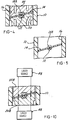
- FIG. 3 shows in simplified form an apparatus for carrying out the thermoforming of the disc 14.
- the apparatus includes a fixed support 20 inserted into the bore 16 from below the disc 14, and a movable piston 22 inserted from above, after lowering the throttle body 10 so as to position the underside.
- the support 20 and piston 22 are adapted to be heated as by the flow of heated fluid from a source 24, 26 into cavities 28, 30 (or by an electrical heater coil disposed therein).
- the piston 22 is able to be advanced as by an actuator 32 during operation.
- the support 20 has an inclined upper surface 34 relieved at 36 to accommodate the shaft 12, and initially the underside of the disc 14 rests on the surface 34 as the throttle body housing 10 is lowered onto the support 20.
- the piston 22 has a corresponding inclined surface 38 relieved at 40 to accommodate the shaft 12. The piston 22 is advanced to engage the disc 14 and exert a squeezing pressure on the upper surface of the disc 14.
- Heat conducted from the piston 22 and support 20 causes the material of the disc 14 to be slightly extruded radially outwardly as shown in Figure 4 until it engages the wall of the bore 16. This may create a slight annular bulge at the perimeter of the disc 14.
- Detection of the slightly increased resistance to movement of the piston 22 can be used as a control signal to discontinue the piston advance at this stage.
- the support 20 and piston 22 are then allowed to cool, which may be speeded by active cooling prior to withdrawal of the piston 22 and removal of the assembly from the support 20.
- Figures 8 and 9 show details of a refined version of the support 20A, which has narrow curving segments 42A, 42, either semi-circular or semi-elliptical in shape, corresponding to the disc shape.
- the segments 42A, 42B are affixed on either side of a relieved area 36A to create a raised area recessed in from the outer perimeter of the support 20A.
- the ring segments 42A, 42B concentrate the extruding pressure in a narrow annular area adjacent the outer perimeter of the disc 14.
- An outer heat insulating jacket 44 may also be provided.
- a suitably configured inner cavity 46 may also be provided to provide a proper rate of cool down after each forming cycle.
- Alternate ways of heating the disc 14 can be employed, such as by using one or more laser sources 48 shown in Figure 10, which generate laser beams passing through piston 22B and support 20B, which are made of a material transparent to the particular laser beam frequency for this purpose to impinge and heat the outer perimeter of the disc 14. This causes appropriate heating of the disc 14 to cause softening sufficient to carry out the extruding process described.
- Ultrasonic energy may alternatively be utilized for carrying out the heating process.
Landscapes
- Engineering & Computer Science (AREA)
- Mechanical Engineering (AREA)
- Health & Medical Sciences (AREA)
- Physics & Mathematics (AREA)
- General Engineering & Computer Science (AREA)
- Toxicology (AREA)
- Electromagnetism (AREA)
- Oral & Maxillofacial Surgery (AREA)
- Thermal Sciences (AREA)
- Chemical & Material Sciences (AREA)
- Composite Materials (AREA)
- Lift Valve (AREA)
- Control Of Throttle Valves Provided In The Intake System Or In The Exhaust System (AREA)
Abstract
Description
Claims (15)
- A process for manufacturing an air flow throttle valve comprised of a throttle body formed with an air flow passage comprising a bore extending along an axis through said throttle body, and a valve disc mounted on a pivoted shaft extending across said bore, said process comprising the steps of:making said throttle body, disc and shaft as separate parts, with said disc constructed of a deformable material and undersized with respect to said bore;assembling said shaft to said throttle body so as to extend across said bore of said throttle body, and assembling said disc to said shaft within said bore;finally sizing said disc by deforming said disc to cause said disc material to flow radially outward to a wall defining said throttle body bore.
- The process according to claim 1 wherein said disc is constructed of a thermoformable material and wherein said deforming step includes the step of heating said disc.
- The process according to claim 1 further including the step of positioning said shaft and disc so as to orient said disc extending across said bore at a small angle away from normal to said bore axis prior to final sizing of said disc.
- The process according to claim 2 further including the step of applying pressure to opposite faces of said disc while heating said disc to cause said disc material to be squeezed radially outward to be exactly sized to the inside of said bore, and the step of cooling said disc after being sized.
- The process according to claim 3 further including the step of setting a closed shaft position at a slightly greater angle than the angle at which said disc is resized.
- The process according to claim 4 wherein said step of applying pressure to said disc, tools are inserted from opposite ends of said bore and into contact with an opposite radial face of said disc.
- The process according to claim 6 wherein said step of heating said disc is carried out by heating said tools.
- The process according to claim 1 wherein said step of heating said disc is carried out by directing a laser beam at the perimeter of said disc.
- The process according to claim 1 wherein said throttle body is formed by being molded from plastic.
- The process according to claim 9 wherein said throttle body is molded from a plastic having a higher melting temperature than said disc.
- The process according to claim 1 wherein said tool pressure is discontinued upon sensing an increase in resistance as said disc material contacts said bore wall.
- The process according to claim 1 wherein said step of heating said disc includes the step of applying ultrasonic energy to the perimeter of said disc.
- The process according to claim 1 wherein said disc is fixedly attached to said shaft prior to said final sizing step, whereby said disc is also centered in said bore when being thermoformed to size.
- The process according to claim 3 wherein said disc is loosely assembled to said shaft during said final sizing step, said shaft is rotated towards a closed position to center said disc, and said disc is thereafter fixedly attached to said shaft to secure said centered position.
- The air flow throttle valve made by the process of claim 1.
Applications Claiming Priority (2)
| Application Number | Priority Date | Filing Date | Title |
|---|---|---|---|
| US08/921,920 US5902426A (en) | 1997-08-27 | 1997-08-27 | Process for manufacturing an air flow valve |
| US921920 | 1997-08-27 |
Publications (3)
| Publication Number | Publication Date |
|---|---|
| EP0899073A2 true EP0899073A2 (en) | 1999-03-03 |
| EP0899073A3 EP0899073A3 (en) | 2001-05-16 |
| EP0899073B1 EP0899073B1 (en) | 2004-04-07 |
Family
ID=25446185
Family Applications (1)
| Application Number | Title | Priority Date | Filing Date |
|---|---|---|---|
| EP98114874A Expired - Lifetime EP0899073B1 (en) | 1997-08-27 | 1998-08-07 | Process for manufacturing an air flow valve |
Country Status (4)
| Country | Link |
|---|---|
| US (1) | US5902426A (en) |
| EP (1) | EP0899073B1 (en) |
| KR (1) | KR100310516B1 (en) |
| DE (1) | DE69822944T2 (en) |
Cited By (8)
| Publication number | Priority date | Publication date | Assignee | Title |
|---|---|---|---|---|
| WO2001026877A1 (en) * | 1999-10-12 | 2001-04-19 | Siemens Automotive Inc | Process to evenly form an air flow valve |
| EP1065361A3 (en) * | 1999-06-29 | 2001-05-30 | Siemens Canada Limited | Throttle shaft and butterfly construction |
| EP1083316A3 (en) * | 1999-09-08 | 2001-09-12 | Siemens Canada limited | Throttle shaft and plate assembly |
| WO2002075120A3 (en) * | 2001-03-15 | 2002-11-21 | Bosch Gmbh Robert | Valve assembly for an internal combustion engine and method of manufacturing |
| EP1096124A3 (en) * | 1999-11-01 | 2003-01-29 | Denso Corporation | Valve system for intake air controller for internal combustion engine and manufacturing the same |
| WO2003019053A1 (en) * | 2001-08-23 | 2003-03-06 | Siemens Aktiengesellschaft | Butterfly valve connection piece for an internal combustion engine |
| EP1231370A3 (en) * | 2001-02-07 | 2003-12-10 | Delphi Technologies, Inc. | Laser welded air control valve and method |
| EP1095751A3 (en) * | 1999-11-01 | 2004-06-09 | Siemens Canada Limited | Thermoforming fixture for an air flow valve within a curved air flow bore |
Families Citing this family (11)
| Publication number | Priority date | Publication date | Assignee | Title |
|---|---|---|---|---|
| DE10023348A1 (en) * | 2000-05-12 | 2001-12-13 | Mannesmann Vdo Ag | Method for producing a housing for a throttle valve assembly and throttle valve assembly |
| US7044439B2 (en) * | 2001-03-03 | 2006-05-16 | Oechsler Aktiengesellschaft | Motor driven value |
| JP2003159752A (en) * | 2001-11-27 | 2003-06-03 | Ykk Corp | Method and apparatus for welding synthetic resin body by high frequency or ultrasonic heating |
| DE10240910A1 (en) * | 2002-09-04 | 2004-03-18 | Siemens Ag | Method for closing a butterfly valve casing comprises attaching lower section of flap to shaft, edge sections to this and upper section to all three sections, space between them then being filled with foam |
| CN1914026B (en) * | 2004-02-03 | 2011-06-29 | 日本发条株式会社 | Ultrasonic welding structure and ultrasonic welding method |
| JP4080492B2 (en) * | 2005-03-31 | 2008-04-23 | 日本発条株式会社 | Bonded body and bonding method |
| DE102006009155A1 (en) * | 2006-02-24 | 2007-08-30 | Mahle International Gmbh | Switching valve and associated manufacturing method |
| DE102006039827A1 (en) * | 2006-08-25 | 2008-02-28 | Mahle International Gmbh | Switching device for controlling a gas flow |
| US20110127693A1 (en) * | 2009-11-05 | 2011-06-02 | Denso Corporation | Method of manufacturing throttle valves and throttle bodies |
| US8453621B2 (en) | 2010-10-22 | 2013-06-04 | Magneti Marelli Powertrain Usa, Llc | Integrated throttle body for electronic fuel injection system and method of manufacture |
| US9627948B2 (en) * | 2014-04-11 | 2017-04-18 | Remy Technologies Llc | Electric machine with combined insulator and terminal assembly |
Family Cites Families (8)
| Publication number | Priority date | Publication date | Assignee | Title |
|---|---|---|---|---|
| US4647325A (en) * | 1984-07-12 | 1987-03-03 | Presto Products, Incorporated | Ultrasonic spot welding tip assembly and method for using the same |
| JPH0613193B2 (en) * | 1987-03-16 | 1994-02-23 | 富士写真フイルム株式会社 | Method for laminating thermoplastic resin member |
| US4859378A (en) * | 1988-10-28 | 1989-08-22 | Branson Ultrasonics Corporation | Method of ultrasonically assembling workpieces |
| DE69020567C5 (en) * | 1990-10-24 | 2007-08-16 | Volvo Car Corp. | Valve assembly. |
| AT400422B (en) * | 1992-02-14 | 1995-12-27 | Pollmann Uhr & App Ernst | METHOD AND DEVICE FOR ADAPTING COMPONENTS |
| FR2687601A1 (en) * | 1992-02-26 | 1993-08-27 | Plastic Omnium Cie | Method of manufacturing a butterfly valve, device for implementing it and butterfly valve obtained by this method |
| EP0567426B1 (en) * | 1992-04-21 | 1997-01-08 | Emerson Electric Co. | Ultrasonic welding method |
| US5658408A (en) * | 1992-04-21 | 1997-08-19 | Branson Ultrasonics Corporation | Method for processing workpieces by ultrasonic energy |
-
1997
- 1997-08-27 US US08/921,920 patent/US5902426A/en not_active Expired - Lifetime
-
1998
- 1998-08-07 DE DE69822944T patent/DE69822944T2/en not_active Expired - Lifetime
- 1998-08-07 EP EP98114874A patent/EP0899073B1/en not_active Expired - Lifetime
- 1998-08-27 KR KR1019980034771A patent/KR100310516B1/en not_active Expired - Fee Related
Cited By (13)
| Publication number | Priority date | Publication date | Assignee | Title |
|---|---|---|---|---|
| EP1065361A3 (en) * | 1999-06-29 | 2001-05-30 | Siemens Canada Limited | Throttle shaft and butterfly construction |
| US6354567B1 (en) | 1999-06-29 | 2002-03-12 | Siemens Canada Limited | Throttle shaft and butterfly construction |
| EP1083316A3 (en) * | 1999-09-08 | 2001-09-12 | Siemens Canada limited | Throttle shaft and plate assembly |
| WO2001026877A1 (en) * | 1999-10-12 | 2001-04-19 | Siemens Automotive Inc | Process to evenly form an air flow valve |
| US6572795B1 (en) | 1999-10-12 | 2003-06-03 | Siemens Vdo Automotive Inc. | Process and apparatus to evenly form an air flow valve |
| US6766580B2 (en) | 1999-11-01 | 2004-07-27 | Denso Corporation | Method for assembling a valve in a passage in a valve system |
| EP1096124A3 (en) * | 1999-11-01 | 2003-01-29 | Denso Corporation | Valve system for intake air controller for internal combustion engine and manufacturing the same |
| EP1095751A3 (en) * | 1999-11-01 | 2004-06-09 | Siemens Canada Limited | Thermoforming fixture for an air flow valve within a curved air flow bore |
| US6565067B1 (en) | 1999-11-01 | 2003-05-20 | Denso Corporation | Valve system for intake air controller for internal combustion engine and manufacturing the same |
| EP1231370A3 (en) * | 2001-02-07 | 2003-12-10 | Delphi Technologies, Inc. | Laser welded air control valve and method |
| WO2002075120A3 (en) * | 2001-03-15 | 2002-11-21 | Bosch Gmbh Robert | Valve assembly for an internal combustion engine and method of manufacturing |
| WO2003019053A1 (en) * | 2001-08-23 | 2003-03-06 | Siemens Aktiengesellschaft | Butterfly valve connection piece for an internal combustion engine |
| US7143996B2 (en) | 2001-08-23 | 2006-12-05 | Siemens Ag | Throttle connection fitting for an internal combustion engine |
Also Published As
| Publication number | Publication date |
|---|---|
| DE69822944T2 (en) | 2005-04-07 |
| EP0899073B1 (en) | 2004-04-07 |
| KR100310516B1 (en) | 2001-12-17 |
| DE69822944D1 (en) | 2004-05-13 |
| KR19990023917A (en) | 1999-03-25 |
| EP0899073A3 (en) | 2001-05-16 |
| US5902426A (en) | 1999-05-11 |
Similar Documents
| Publication | Publication Date | Title |
|---|---|---|
| US5902426A (en) | Process for manufacturing an air flow valve | |
| US2982999A (en) | Method of molding shaft seals | |
| EP0355589B1 (en) | Mold for molding optical disk base | |
| US5901772A (en) | Method for casting pistons | |
| KR100419127B1 (en) | Disc-molding mold | |
| EP1560688B1 (en) | Tire mold and method for making a tire mold | |
| EP2992210B1 (en) | Wax actuator with high cycle life | |
| CN114696521B (en) | Permanent magnet synchronous motor and control method thereof | |
| EP1220742B1 (en) | Process and tool for evenly forming an air flow valve | |
| JPH0544893B2 (en) | ||
| US6007746A (en) | Method for manufacturing preforms used in molding optical elements and method for manufacturing and molding optical elements | |
| CN109676843B (en) | Mold and mold manufacturing method | |
| JP3580119B2 (en) | Forging die equipment | |
| CN114901449B (en) | Insert sintered part and method for manufacturing same | |
| JP3936651B2 (en) | Mold for molding disk substrate | |
| JP3524595B2 (en) | Injection mold | |
| GB2193270A (en) | Shaft seal | |
| CN224051579U (en) | Vulcanizing equipment simulating oil seal lip structure | |
| CN220382890U (en) | Motor signal magnetic ring | |
| JPS62189150A (en) | Manufacture of tape reel | |
| JPH07256385A (en) | Method for forging housing for ball joint | |
| EP1095751A2 (en) | Thermoforming fixture for an air flow valve within a curved air flow bore | |
| US4397627A (en) | Apparatus for molding a recorded disc | |
| JPS63224919A (en) | Stamper holding structure in disk molding machine | |
| JP2536797Y2 (en) | Closed forging die equipment |
Legal Events
| Date | Code | Title | Description |
|---|---|---|---|
| PUAI | Public reference made under article 153(3) epc to a published international application that has entered the european phase |
Free format text: ORIGINAL CODE: 0009012 |
|
| AK | Designated contracting states |
Kind code of ref document: A2 Designated state(s): DE FR GB IT |
|
| AX | Request for extension of the european patent |
Free format text: AL;LT;LV;MK;RO;SI |
|
| 17P | Request for examination filed |
Effective date: 19990809 |
|
| PUAL | Search report despatched |
Free format text: ORIGINAL CODE: 0009013 |
|
| AK | Designated contracting states |
Kind code of ref document: A3 Designated state(s): AT BE CH CY DE DK ES FI FR GB GR IE IT LI LU MC NL PT SE |
|
| AX | Request for extension of the european patent |
Free format text: AL;LT;LV;MK;RO;SI |
|
| RIC1 | Information provided on ipc code assigned before grant |
Free format text: 7B 29C 43/02 A, 7B 29C 43/18 B, 7F 16K 27/02 B, 7B 29C 43/36 B, 7B 29C 65/60 - |
|
| AKX | Designation fees paid |
Free format text: DE FR GB IT |
|
| 17Q | First examination report despatched |
Effective date: 20020318 |
|
| RAP1 | Party data changed (applicant data changed or rights of an application transferred) |
Owner name: SIEMENS VDO AUTOMOTIVE CORPORATION |
|
| GRAP | Despatch of communication of intention to grant a patent |
Free format text: ORIGINAL CODE: EPIDOSNIGR1 |
|
| GRAS | Grant fee paid |
Free format text: ORIGINAL CODE: EPIDOSNIGR3 |
|
| GRAA | (expected) grant |
Free format text: ORIGINAL CODE: 0009210 |
|
| AK | Designated contracting states |
Kind code of ref document: B1 Designated state(s): DE FR GB IT |
|
| PG25 | Lapsed in a contracting state [announced via postgrant information from national office to epo] |
Ref country code: IT Free format text: LAPSE BECAUSE OF FAILURE TO SUBMIT A TRANSLATION OF THE DESCRIPTION OR TO PAY THE FEE WITHIN THE PRE;WARNING: LAPSES OF ITALIAN PATENTS WITH EFFECTIVE DATE BEFORE 2007 MAY HAVE OCCURRED AT ANY TIME BEFORE 2007. THE CORRECT EFFECTIVE DATE MAY BE DIFFERENT FROM THE ONE RECORDED.SCRIBED TIME-LIMIT Effective date: 20040407 Ref country code: FR Free format text: LAPSE BECAUSE OF FAILURE TO SUBMIT A TRANSLATION OF THE DESCRIPTION OR TO PAY THE FEE WITHIN THE PRESCRIBED TIME-LIMIT Effective date: 20040407 |
|
| REG | Reference to a national code |
Ref country code: GB Ref legal event code: FG4D |
|
| REF | Corresponds to: |
Ref document number: 69822944 Country of ref document: DE Date of ref document: 20040513 Kind code of ref document: P |
|
| PG25 | Lapsed in a contracting state [announced via postgrant information from national office to epo] |
Ref country code: GB Free format text: LAPSE BECAUSE OF NON-PAYMENT OF DUE FEES Effective date: 20040807 |
|
| PLBE | No opposition filed within time limit |
Free format text: ORIGINAL CODE: 0009261 |
|
| STAA | Information on the status of an ep patent application or granted ep patent |
Free format text: STATUS: NO OPPOSITION FILED WITHIN TIME LIMIT |
|
| EN | Fr: translation not filed | ||
| 26N | No opposition filed |
Effective date: 20050110 |
|
| GBPC | Gb: european patent ceased through non-payment of renewal fee |
Effective date: 20040807 |
|
| PGFP | Annual fee paid to national office [announced via postgrant information from national office to epo] |
Ref country code: DE Payment date: 20120831 Year of fee payment: 15 |
|
| PG25 | Lapsed in a contracting state [announced via postgrant information from national office to epo] |
Ref country code: DE Free format text: LAPSE BECAUSE OF NON-PAYMENT OF DUE FEES Effective date: 20140301 |
|
| REG | Reference to a national code |
Ref country code: DE Ref legal event code: R119 Ref document number: 69822944 Country of ref document: DE Effective date: 20140301 |