EP0898435A2 - Digital cordless telephone system - Google Patents
Digital cordless telephone system Download PDFInfo
- Publication number
- EP0898435A2 EP0898435A2 EP98110276A EP98110276A EP0898435A2 EP 0898435 A2 EP0898435 A2 EP 0898435A2 EP 98110276 A EP98110276 A EP 98110276A EP 98110276 A EP98110276 A EP 98110276A EP 0898435 A2 EP0898435 A2 EP 0898435A2
- Authority
- EP
- European Patent Office
- Prior art keywords
- connection
- central unit
- portable part
- telephone system
- cordless telephone
- Prior art date
- Legal status (The legal status is an assumption and is not a legal conclusion. Google has not performed a legal analysis and makes no representation as to the accuracy of the status listed.)
- Ceased
Links
Images
Classifications
-
- H—ELECTRICITY
- H04—ELECTRIC COMMUNICATION TECHNIQUE
- H04W—WIRELESS COMMUNICATION NETWORKS
- H04W84/00—Network topologies
- H04W84/02—Hierarchically pre-organised networks, e.g. paging networks, cellular networks, WLAN [Wireless Local Area Network] or WLL [Wireless Local Loop]
- H04W84/10—Small scale networks; Flat hierarchical networks
- H04W84/16—WPBX [Wireless Private Branch Exchange]
-
- H—ELECTRICITY
- H04—ELECTRIC COMMUNICATION TECHNIQUE
- H04M—TELEPHONIC COMMUNICATION
- H04M1/00—Substation equipment, e.g. for use by subscribers
- H04M1/72—Mobile telephones; Cordless telephones, i.e. devices for establishing wireless links to base stations without route selection
- H04M1/725—Cordless telephones
- H04M1/72502—Cordless telephones with one base station connected to a single line
- H04M1/72505—Radio link set-up procedures
Definitions
- the invention relates to a digital cordless telephone system according to the Preamble of claim 1.
- Cordless telephone systems are telephone systems with a central unit and usually a plurality of end devices to which telephone calls arrive or from which telephone connections can be made.
- a Such a terminal is usually a mobile radio telephone, the portable Part, which has a radio station, the Fix Part, with the central unit connected is. At rest, the portable part is usually in one Charging station, e.g. for charging the batteries.
- a radio channel is assigned from the fixed part to the portable part; the connection is then from the fix part to the central unit via a data line switched through.
- the central unit manages the Connection via an outside interface to an external switching center, one node further. The connection to the external device is established made in a known manner.
- From the portable part can over the Central unit also an internal connection to another terminal be switched, e.g. if the cordless phone system as In-house telephone system is used.
- the terminal is either another Radio telephone that has a fix part with a free radio channel and sufficient field strength is connected to the central unit, or a ordinary phone.
- the reverse connection from one Terminal device for the portable part takes place accordingly via the central unit and the fix part assigned to the portable part.
- Fix Part and Portable Part act as senders and receivers of Information in a digital transmission format via a Radio link with a range of about 50 to 300 meters. It can to disturbances in the data transmission between fix part and portable part and thereby to bit errors in the entire transmission channel Movable and static influences come from the transmitter emitted alternating electromagnetic field can influence, as well due to system-related disturbances and influences. Furthermore, the Data transmission disrupted when the end user moves to the edge of the The sending and receiving area of the fix part is approaching.
- the central unit of the cordless telephone system monitors with one Bit error monitoring module the bit errors in the transmission channel and breaks the connection to the portable part with a certain number of bit errors.
- the connection to the conversation partner i.e. to another external or internal terminal, is then defined by the central processing unit dismantled, which leads to unwanted termination of calls. Also builds the central unit disconnects when one of the participants hangs up. For this purpose, the central unit has a shutdown monitoring module.
- a disadvantage of known digital cordless telephone systems is that the interruption of the transmission due to the susceptibility of the Area between fix part and portable part often uncontrollable and conversations get lost unintentionally.
- the invention is therefore based on the object of a cordless telephone system to create, at which unwanted dropouts are largely avoided.
- the task is solved by a cordless telephone system according to the The preamble of claim 1, which has an evaluation unit which is able to recognize whether the connection between the central unit and Portable part due to shutdown or transmission errors was interrupted, the central unit in the event of a fault Transfer the connection between the central unit and one holds another terminal in a hold memory and the new one Connection establishment to the portable part after a predetermined Automatically initiates the time interval.
- the central unit preferably selects in the event of a transmission error Disconnection to the portable part at a predetermined drop target, when restoring the original connection to the portable Part does not succeed within a certain time.
- This target is for example, another terminal of the cordless system that the user of the unreachable portable part to find out To continue the conversation. It is also advantageous if the terminal is on Answering machine is on which the other party is one Can leave message.
- the selection of multiple dropping targets is preferred by the Central unit provided.
- the central unit tries to connect to one further dropping target, e.g. an answering machine. Only after unsuccessful selection of all predetermined launch targets will Connection to the waiting conversation partner of the Portible Part user mined by definition.
- each portable part There is preferably at least one drop target for each portable part individually adjustable. This enables the user of the A portable part in the event of an unwanted termination of a call can look up to him and continue the conversation there.
- the call partner is preferably called by the central unit an announcement about the unwanted connection breakdown and the Attempted to reconnect informed and asked not hanging up. There remains the restoration of the connection to the portable Part or the transfer to a dropping target unsuccessful, the Central unit to the interlocutor with an announcement that the Overall connection is now cleared down.
- Digital cordless systems can be made essential by the invention be made more user-friendly because unwanted system crashes, especially due to temporary transmission problems, largely avoided.
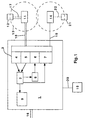
- FIG. 1 is a block diagram of a cordless telephone system according to the invention shown. It is only those essential to the invention Components shown.
- the telephone system consists of a central unit 1 with three terminals 12, 21 and 15.
- the terminals 12 and 21 are Radio telephones, portable parts, each of which has a fixed radio unit, the Fix Part 11 or 14.
- the terminal 15 is a fixed one ordinary telephone or answering machine.
- Fix Part 11.14 is over a data line 18 or 19 is permanently connected to the central unit 1.
- This Radio station can provide one or more radio channels and illuminates a certain space, which is a circle around the Fix Part 11 or 14 is shown. Between the Fix Part 11 and the Portable Part 12 can be within this range 13, marked by the dashed line Circle, data are transmitted over a radio link 17 network-bound.
- the central unit in this way there is a partially network-connected telephone connection between the central unit 1 and the portable part 12 via the fix part 11 producible.
- the central unit in turn, can use an outside interface 16 connections via the outside line or internally to other end devices enter within the cordless system. Accordingly, between the fix part 14 and the portable part 21 data over a radio link 22 be transmitted.
- connection is from an external caller via the central office interface 16 at the central unit 1.
- the Connection control unit 3 mediates the connection within the Cordless systems via the data line 18 to the Fix Part 11 and monitors the connection.
- the fix part connects with the Interlocutor at portable part 12 via radio link 17.
- the central unit 1 of the cordless telephone system can advantageously between wanted by the user of the Portable Part 12 and unintended breakdown of the connection between Distinguish central unit 1 and portable part 12.
- the Evaluation unit 2 both the bit error monitoring module 4 and that Shutdown monitoring module 5.
- Has the shutdown monitoring module 5 an intentional shutdown of the connection from the central unit 1 to If portable part 12 is identified, evaluation unit 2 gives the connection to the external end user for dismantling as defined.
- Bit error monitoring module 4 the connection between Central unit and portable part triggered due to transmission interference, this detects the evaluation unit 2 and causes the connection is placed in a latch 9 for the external end user.
- the Central unit 1 via the connection control unit 3 the redial of the Portable Part 12. This is done by means of a redial unit 6. If the problem that caused the connection to be terminated was to have a temporary influence, the Portable Part user can usually be reached again after this time interval.
- connection control unit 3 tries during a predetermined one Time interval to reconnect to the portable part. If this does not succeed within this time, e.g. because the portable's battery Part 12 is unloaded or all radio channels are busy, so choose the Connection control unit 3 by means of a release unit 7 another End device as a predetermined drop target.
- a release unit 7 another End device as a predetermined drop target.
- the drop targets are preferably individual for the each portable part can be set and selected one after the other, until a connection is made. Then the external connection is off taken from the memory 9 and automatically to the now activated Terminal 21, 15 switched through. The external call partner can then the conversation with the user of the respective drop target 21 or 15 resume or leave a message.
- the central unit 1 also causes the external An announcement text is played when the connection is broken, which alerts him to the attempt to reconnect and asks him not to hang up. After unsuccessful re-or This is also forwarded to the caller via an announcement text communicated.
Landscapes
- Engineering & Computer Science (AREA)
- Computer Networks & Wireless Communication (AREA)
- Signal Processing (AREA)
- Mobile Radio Communication Systems (AREA)
- Noise Elimination (AREA)
Abstract
Description
Die Erfindung betrifft ein digitales Cordless-Telefonsystem gemäß dem
Oberbegriff von Anspruch 1.The invention relates to a digital cordless telephone system according to the
Preamble of
Cordless-Telefonsysteme sind Telefonsysteme mit einer Zentraleinheit und meist einer Mehrzahl von Endgeräten, an denen Telefonanrufe ankommen bzw. von denen aus Telefonverbindungen hergestellt werden können. Ein derartiges Endgerät ist in der Regel ein mobiles Funktelefon, der Portible Part, welches über eine Funkstation, den Fix Part, mit der Zentraleinheit verbunden ist. Im Ruhefall befindet sich der Portible Part meist in einer Ladestation, z.B. zur Aufladung der Batterien. Bei einer Telefonverbindung wird vom Fix Part zum Portible Part ein Funkkanal belegt; die Verbindung wird dann vom Fix Part über eine Datenleitung zur Zentraleinheit durchgeschaltet. Zur Herstellung einer Verbindung über die Amtsleitung mit einem externen Telefonanschluß leitet die Zentraleinheit die Verbindung über eine Amtsschnittstelle an eine externe Vermittlungsstelle, einen Netzknoten weiter. Der Verbindungsaufbau zum externen Gerät wird in bekannter Weise vorgenommen. Vom Portible Part kann über die Zentraleinheit auch eine interne Verbindung zu einem weiteren Endgerät geschaltet werden, z.B. wenn das Cordless-Telefonsystem als Haustelefonanlage verwendet wird. Das Endgerät ist entweder ein weiteres Funktelefon, das über einen Fix Part mit freiem Funkkanal und ausreichender Feldstärke mit der Zentraleinheit verbunden ist, oder ein gewöhnliches Telefon. Der umgekehrte Verbindungsaufbau von einem Endgerät zum Portible Part erfolgt entsprechend über die Zentraleinheit und den dem Portible Part zugeordneten Fix Part.Cordless telephone systems are telephone systems with a central unit and usually a plurality of end devices to which telephone calls arrive or from which telephone connections can be made. A Such a terminal is usually a mobile radio telephone, the portable Part, which has a radio station, the Fix Part, with the central unit connected is. At rest, the portable part is usually in one Charging station, e.g. for charging the batteries. With a telephone connection a radio channel is assigned from the fixed part to the portable part; the connection is then from the fix part to the central unit via a data line switched through. To establish a connection via the outside line with an external telephone connection, the central unit manages the Connection via an outside interface to an external switching center, one node further. The connection to the external device is established made in a known manner. From the portable part can over the Central unit also an internal connection to another terminal be switched, e.g. if the cordless phone system as In-house telephone system is used. The terminal is either another Radio telephone that has a fix part with a free radio channel and sufficient field strength is connected to the central unit, or a ordinary phone. The reverse connection from one Terminal device for the portable part takes place accordingly via the central unit and the fix part assigned to the portable part.
Fix Part und Portible Part fungieren als Sender und Empfänger von Informationen in einem digitalen Übertragungsformat über eine Funkstrecke mit einer Reichweite von etwa 50 bis 300 Metern. Dabei kann es zu Störungen der Datenübermittlung zwischen Fix Part und Portible Part und dadurch zu Bitfehlern im gesamten Übertragungskanal durch bewegliche und statische Einflüsse kommen, welche das vom Sender ausgestrahlte elektromagnetische Wechselfeld beeinflussen können, sowie durch systembedingte Störungen und Beeinflussungen. Weiterhin wird die Datenübermittlung gestört, wenn sich der Endbenutzer dem Rand des Sende- und Empfangsbereichs des Fix Part nähert. Fix Part and Portable Part act as senders and receivers of Information in a digital transmission format via a Radio link with a range of about 50 to 300 meters. It can to disturbances in the data transmission between fix part and portable part and thereby to bit errors in the entire transmission channel Movable and static influences come from the transmitter emitted alternating electromagnetic field can influence, as well due to system-related disturbances and influences. Furthermore, the Data transmission disrupted when the end user moves to the edge of the The sending and receiving area of the fix part is approaching.
Die Zentraleinheit des Cordless-Telefonsystems überwacht mit einem Bitfehler-Überwachungsmodul die Bitfehler im Übertragungskanal und bricht die Verbindung zum Portible Part bei einer gewissen Bitfehlerzahl ab. Die Verbindung zum Gesprächspartner, d.h. zu einem weiteren externen oder internen Endgerät, wird dann von der Zentraleinheit nach Definition abgebaut, was zu ungewünschten Gesprächsabbrüchen führt. Ebenso baut die Zentraleinheit die Verbindung ab, wenn einer der Teilnehmer auflegt. Dazu weist die Zentraleinheit ein Abschalt-Überwachungsmodul auf.The central unit of the cordless telephone system monitors with one Bit error monitoring module the bit errors in the transmission channel and breaks the connection to the portable part with a certain number of bit errors. The connection to the conversation partner, i.e. to another external or internal terminal, is then defined by the central processing unit dismantled, which leads to unwanted termination of calls. Also builds the central unit disconnects when one of the participants hangs up. For this purpose, the central unit has a shutdown monitoring module.
Nachteilig an bekannten digitalen Cordless-Telefonsystemen ist, daß durch die Unterbrechung der Übertragung aufgrund der Störanfälligkeit des Bereichs zwischen Fix Part und Portible Part häufig unkontrollierbar und ungewollt Gespräche verloren gehen.A disadvantage of known digital cordless telephone systems is that the interruption of the transmission due to the susceptibility of the Area between fix part and portable part often uncontrollable and conversations get lost unintentionally.
Der Erfindung liegt daher die Aufgabe zugrunde, ein Cordless-Telefonsystem zu schaffen, bei welchem ungewollte Gesprächsabbrüche weitestgehend vermieden werden.The invention is therefore based on the object of a cordless telephone system to create, at which unwanted dropouts are largely avoided.
Die Aufgabe wird gelöst durch ein Cordless-Telefonsystem gemäß dem
Oberbegriff von Anspruch 1, das eine Auswerteeinheit aufweist, welche zu
erkennen imstande ist, ob die Verbindung zwischen Zentraleinheit und
Portible Part durch Abschalten oder durch Übertragungsfehler
unterbrochen wurde, wobei die Zentraleinheit im Fall der fehlerhaften
Übertragung die Verbindung zwischen der Zentraleinheit und einem
weiteren Endgerät in einem Haltespeicher hält und den erneuten
Verbindungsaufbau zum Portible Part nach einem vorbestimmten
Zeitintervall automatisch einleitet.The task is solved by a cordless telephone system according to the
The preamble of
Weitere vorteilhafte Ausgestaltungen der Erfindung sind in den Unteransprüchen gekennzeichnet.Further advantageous embodiments of the invention are in the Subclaims marked.
Vorzugsweise wählt die Zentraleinheit bei übertragungsfehlerbedingtem Verbindungsabbruch zum Portible Part ein vorbestimmtes Abwurfziel an, wenn die Wiederherstellung der ursprünglichen Verbindung zum Portible Part innerhalb einer gewissen Zeit nicht gelingt. Dieses Abwurfziel ist beispielsweise ein weiteres Endgerät des Cordless-Systems, das der Benutzer des nicht mehr erreichbaren Portible Part aufsuchen kann, um das Gespräch fortzusetzen. Vorteilhaft ist auch, wenn das Endgerät ein Anrufbeantworter ist, auf dem der andere Gesprächsteilnehmer eine Nachricht hinterlassen kann.The central unit preferably selects in the event of a transmission error Disconnection to the portable part at a predetermined drop target, when restoring the original connection to the portable Part does not succeed within a certain time. This target is for example, another terminal of the cordless system that the user of the unreachable portable part to find out To continue the conversation. It is also advantageous if the terminal is on Answering machine is on which the other party is one Can leave message.
Vorzugsweise ist die Anwahl mehrerer Abwurfziele durch die Zentraleinheit vorgesehen. In dem Fall, daß die Verbindung zum ersten Abwurfziel, z.B. einem Telefonapparat, innerhalb einer gewissen Zeit nicht herstellbar ist, versucht die Zentraleinheit, eine Verbindung zu einem weiteren Abwurfziel, z.B. einem Anrufbeantworter, herzustellen. Erst nach erfolgloser Anwahl sämtlicher vorbestimmter Abwurfziele wird die Verbindung zum wartenden Gesprächspartner des Portible Part-Benutzers definitionsgemäß abgebaut.The selection of multiple dropping targets is preferred by the Central unit provided. In the event that the connection to the first Drop target, e.g. a telephone, not within a certain time can be established, the central unit tries to connect to one further dropping target, e.g. an answering machine. Only after unsuccessful selection of all predetermined launch targets will Connection to the waiting conversation partner of the Portible Part user mined by definition.
Vorzugsweise ist für jeden Portible Part wenigstens ein Abwurfziel individuell einstellbar. Dadurch wird ermöglicht, daß der Benutzer des Portible Part bei ungewolltem Gesprächsabbruch gezielt ein Endgerät in seiner Nähe aufsuchen und das Gespräch dort fortsetzen kann.There is preferably at least one drop target for each portable part individually adjustable. This enables the user of the A portable part in the event of an unwanted termination of a call can look up to him and continue the conversation there.
Der Gesprächspartner wird vorzugsweise von der Zentraleinheit mittels eines Ansagetextes über den ungewollten Verbindungsabbruch und den Versuch der Wiederherstellung der Verbindung informiert und gebeten, nicht aufzulegen. Bleibt die Wiederherstellung der Verbindung zum Portible Part bzw. die Weitervermittlung an ein Abwurfziel erfolglos, teilt die Zentraleinheit dem Gesprächspartner durch einen Ansagetext mit, daß die Gesamtverbindung nunmehr abgebaut wird.The call partner is preferably called by the central unit an announcement about the unwanted connection breakdown and the Attempted to reconnect informed and asked not hanging up. There remains the restoration of the connection to the portable Part or the transfer to a dropping target unsuccessful, the Central unit to the interlocutor with an announcement that the Overall connection is now cleared down.
Durch die Erfindung können digitale Cordless-Systems wesentlich anwendungsfreundlicher gemacht werden, da ungewollte Systemabbrüche, insbesondere aufgrund vorübergehender Übertragunsgstörungen, weitgehend vermieden werden.Digital cordless systems can be made essential by the invention be made more user-friendly because unwanted system crashes, especially due to temporary transmission problems, largely avoided.
Ein Beispiel der Erfindung ist in der Zeichnung dargestellt und im folgenden beschrieben.An example of the invention is shown in the drawing and in described below.
In Figur 1 ist ein Blockschaltbild eines erfindungsgemäßen Cordless-Telefonsystems
dargestellt. Es sind nur die erfindungswesentlichen
Komponenten gezeigt. Das Telefonsystem besteht aus einer Zentraleinheit 1
mit drei Endgeräten 12, 21 und 15. Die Endgeräte 12 und 21 sind
Funktelefone, Portible Parts, denen jeweils eine ortsfeste Funkeinheit, der
Fix Part 11 bzw. 14, zugeordnet ist. Das Endgerät 15 ist eine ortsfestes
gewöhnliches Telefon oder ein Anrufbeantworter. Der Fix Part 11,14 ist über
eine Datenleitung 18 bzw. 19 fest mit der Zentraleineit 1 verbunden. Diese
Funkstation kann einen oder mehrere Funkkanäle zur Verfügung stellen
und leuchtet einen gewissen Raum aus, der als Kreis um den Fix Part 11
bzw. 14 dargestellt ist. Zwischen dem Fix Part 11 und dem Portible Part 12
können innerhalb dieser Reichweite 13, markiert durch den gestrichelten
Kreis, Daten über eine Funkstrecke 17 netzungebunden übertragen werden.
Auf diese Weise ist eine teilweise netzungebundene Telefonverbindung
zwischen der Zentraleinheit 1 und dem Portible Part 12 über den Fix Part 11
herstellbar. Die Zentraleinheit wiederum kann über eine Amtsschnittstelle
16 Verbindungen über die Amtsleitung oder intern zu weiteren Endgeräten
innerhalb des Cordless-Systems eingehen. Entsprechend können zwischen
dem Fix part 14 und dem Portible Part 21 Daten über eine Funkstrecke 22
übermittelt werden.In Figure 1 is a block diagram of a cordless telephone system according to the invention
shown. It is only those essential to the invention
Components shown. The telephone system consists of a
Ein Beispiel für eine Verbindung mit dem Portible Part 12 ist in Figur 1
gepunktet eingezeichnet. Die Verbindung geht von einem externen Anrufer
über die Amtsschnittstelle 16 bei der Zentraleinheit 1 ein. Die
Verbindungskontroll-Einheit 3 vermittelt die Verbindung innerhalb des
Cordless-Systems über die Datenleitung 18 an den Fix Part 11 und
überwacht die Verbindung. Der Fix Part stellt die Verbindung mit dem
Gesprächspartner am Portible Part 12 über die Funkstrecke 17 her.An example of a connection with the
Durch statische oder bewegliche Einflüsse innerhalb der Reichweite des Fix
Part-Senders wie auch dadurch, daß der Portible Part 12 die Reichweite 13
verläßt, kann die Datenübertragung zwischen Fix Part 11 und Portible Part
12 und damit der gesamte Übertragungskanal zwischen Portible Part 12 und
Zentraleinheit 1 gestört werden. Mittels eines Bitfehler-Überwachungsmoduls
4 erkennt die Verbindungskontroll-Einheit 3 eine
störungsbedingt erhöhte Bitfehlerrate im Übertragungskanal und löst die
Verbindung zwischen Zentraleinheit 1 und Portible Part 12 auf. Ebenso
erkennt die Verbindungskontroll-Einheit 3 mittels des Abschalt-Überwachungsmoduls
5 ein gewolltes Unterbechen der Verbindung durch
Auflegen seitens des Portible Part-Benutzers.Due to static or moving influences within the reach of the Fix
Part transmitter as well as the fact that the
Die Zentraleinheit 1 des Cordless-Telefonsystems kann in vorteilhafter Weise
zwischen vom Benutzer des Portible Part 12 gewollten und
störungsbedingtem ungewollten Abbruch der Verbindung zwischen
Zentraleinheit 1 und Portible Part 12 unterscheiden. Dazu überwacht die
Auswerteeinheit 2 sowohl das Bitfehler-Überwachungsmodul 4 als auch das
Abschalt-Überwachungsmodul 5. Hat das Abschalt-Überwachungsmodul 5
ein gewolltes Abschalten der Verbindung von der Zentraleinheit 1 zum
Portible Part 12 identifiziert, so gibt die Auswerteeinheit 2 die Verbindung
zum externen Endbenutzer zum Abbau nach Definition frei. Hat jedoch das
Bitfehler-Überwachungsmodul 4 den Abbruch der Verbindung zwischen
Zentraleinheit und Portible Part wegen Übertragungsstörungen ausgelöst,
so erkennt dies die Auswerteeinheit 2 und veranlaßt, daß die Verbindung
zum externen Endbenutzer in einen Haltespeicher 9 gelegt wird.The
Nach einem mit einem Timer 8 einstellbaren Zeitintervall leitet die
Zentraleinheit 1 über die Verbindungskontroll-Einheit 3 die Wiederanwahl
des Portible Part 12 ein. Dies geschieht mittels eine Wiederanwahl-Einheit 6.
Handelte es sich bei der Störung, die zum Abbruch der Verbindung führte,
um einen vorübergehenden Einfluß, so kann der Portible Part-Benutzer
meist nach diesem Zeitintervall wieder erreicht werden.After a time interval that can be set with a
Die Verbindungskontroll-Einheit 3 versucht während eines vorbestimmten
Zeitintervalls, die Verbindung zum Portible Part wiederherzustellen.
Gelingt dies nicht innerhalb dieser Zeit, z.B. weil die Batterie des Portible
Part 12 entladen ist oder alle Funkkanäle besetzt sind, so wählt die
Verbindungskontroll-Einheit 3 mittels einer Abwurf-Einheit 7 ein weiteres
Endgerät als vorbestimmtes Abwurfziel an. Dies ist hier beispielsweise ein
weiterer Portible Part 21, ein gewöhnliches Telefon oder ein
Anrufbeantworter 15. Die Abwurfziele sind vorzugsweise individuell für den
jeweiligen Portible Part einstellbar und werden nacheinander angewählt,
bis eine Verbindung hergestellt ist. Dann wird die externe Verbindung aus
dem Haltespeicher 9 genommen und automatisch zum nunmehr aktivierten
Endgerät 21, 15 durchgeschaltet. Der externe Gesprächspartner kann dann
das Gespräch mit dem Benutzer des jeweiligen Abwurfziels 21 bzw. 15
wieder aufnehmen bzw. eine Nachricht hinterlassen.The
Die Zentraleinheit 1 veranlaßt weiterhin, daß dem externen
Gesprächspartner bei Verbindungsabbruch ein Ansagetext vorgespielt wird,
welcher ihn auf den Versuch, die Verbindung wiederherzustellen, hinweist
und ihn bittet, nicht aufzulegen. Nach erfolgloser Wieder- oder
Weiterverbindung wird dies dem Anrufer ebenfalls über einen Ansagetext
mitgeteilt.The
Claims (8)
eine Auswerteeinheit (2), welche zu erkennen imstande ist, ob die Verbindung zwischen Zentraleinheit (1) und Portible Part (12) durch Abschalten oder durch Übertragungsfehler unterbrochen wurde, wobei die Zentraleinheit (1) im Fall der fehlerhaften Übertragung die Verbindung zwischen der Zentraleinheit und einem weiteren Endgerät in einem Haltespeicher (9) hält und den erneuten Verbindungsaufbau zum Portible Part (12) nach einem vorbestimmten Zeitintervall automatisch einleitet.Digital cordless telephone system, consisting of a central unit (1), which is connected via a data line (18, 19), in particular an ISDN line, to at least one fixed radio unit, the fix part (11, 14), and at least one The mobile part assigned to the fix part (11, 14), the portable part (12, 21), which can be controlled by the fix part for network-connected digital data transmission via a radio link (17, 22), with a connection arriving at the central unit (1) via the data line (18, 19) to the fixed part (11, 14) and possibly via the radio link (17, 22) to the portable part (12, 21) and vice versa a part of the portable part (12, 21) network-connected connection to the central unit (1) and from there to another terminal can be established, and wherein the central unit (1) clears the connection to the portable part (12, 21) if the transmission is faulty or if the connection on the part of the portable part (12) is interrupted by switching off, characterized by
an evaluation unit (2) which is able to recognize whether the connection between the central unit (1) and the portable part (12) was interrupted by switching off or by transmission errors, the central unit (1) in the event of incorrect transmission the connection between the central unit and holds a further terminal in a hold memory (9) and automatically initiates the re-establishment of the connection to the portable part (12) after a predetermined time interval.
daß die Zentraleinheit bei übertragungsfehlerbedingtem Verbindungsabbruch zum Portible Part (12) ein vorbestimmtes Abwurfziel (21, 15), z.B. einen weiteren Portible Part (21), anwählt, wenn die Wiederherstellung der ursprünglichen Verbindung zum Portible Part (12) mißlingt.Digital cordless telephone system according to claim 1, characterized in
that the central unit selects a predetermined drop target (21, 15), for example another portable part (21), if the connection to the portable part (12) is interrupted due to a transmission error, if the restoration of the original connection to the portable part (12) fails.
daß wenigstens ein weiteres Abwurfziel (21, 15) einstellbar ist, welches angewählt wird, wenn die Wiederherstellung der ursprünglichen Verbindung zum Portible Part (12) und die Verbindungsherstellung zum ersten Abwurfziel mißlingt. Digital cordless telephone system according to claim 2, characterized in
that at least one further drop target (21, 15) can be set, which is selected if the restoration of the original connection to the portable part (12) and the connection to the first drop target fails.
daß für jeden Portible Part (12) wenigstens ein Abwurfziel (21, 15) individuell einstellbar ist.Digital cordless telephone system according to claim 2 or 3, characterized in
that for each portable part (12) at least one drop target (21, 15) can be set individually.
daß die Zentraleinheit (1) nach innerhalb einer vorbestimmten Zeitspanne erfolgloser Weitervermittlung der Verbindung an den Portible Part (12) oder ein Abwurfziel (21, 15) die Verbindung zum Endgerät nach Definition abbaut.Digital cordless telephone system according to one of claims 2 to 4, characterized in that
that the central unit (1) clears the connection to the terminal according to the definition after unsuccessful forwarding of the connection to the portable part (12) or a drop target (21, 15) within a predetermined time period.
daß die Zentraleinheit (1) nach übertragungsfehlerbedingtem Verbindungsabbruch zum Portible Part (12) eine automatische Ansage in die Verbindung zum Endgerät einspielt, über die dem Gesprächspartner mitgeteilt wird, daß das System die Wiederherstellung der Verbindung versucht.Digital cordless telephone system according to one of the preceding claims, characterized in that
that the central unit (1), after a connection error to the portable part (12) due to a transmission error, plays an automatic announcement into the connection to the terminal, via which the call partner is informed that the system is trying to reestablish the connection.
daß die Zentraleinheit (1) nach erfolgloser Weitervermittlung der Verbindung an den Portible Part (12) oder ein Abwurfziel (21, 15) den Verbindungsabbruch dem Gesprächspartner über eine automatische Ansage mitteilt.Digital cordless telephone system according to claim 6, characterized in
that the central unit (1) after unsuccessful transfer of the connection to the portable part (12) or a drop target (21, 15) notifies the caller of the call partner via an automatic announcement.
daß das Abwurfziel (21, 15) ein Anrufbeantworter ist.Digital cordless telephone system according to one of the preceding claims, characterized in that
that the dropping target (21, 15) is an answering machine.
Applications Claiming Priority (2)
| Application Number | Priority Date | Filing Date | Title |
|---|---|---|---|
| DE19735473 | 1997-08-16 | ||
| DE19735473A DE19735473C2 (en) | 1997-08-16 | 1997-08-16 | Digital cordless phone system |
Publications (2)
| Publication Number | Publication Date |
|---|---|
| EP0898435A2 true EP0898435A2 (en) | 1999-02-24 |
| EP0898435A3 EP0898435A3 (en) | 2000-02-09 |
Family
ID=7839113
Family Applications (1)
| Application Number | Title | Priority Date | Filing Date |
|---|---|---|---|
| EP98110276A Ceased EP0898435A3 (en) | 1997-08-16 | 1998-06-05 | Digital cordless telephone system |
Country Status (2)
| Country | Link |
|---|---|
| EP (1) | EP0898435A3 (en) |
| DE (1) | DE19735473C2 (en) |
Citations (5)
| Publication number | Priority date | Publication date | Assignee | Title |
|---|---|---|---|---|
| EP0475348A2 (en) * | 1990-09-11 | 1992-03-18 | Nec Corporation | Cordless key telephone system having zone switching function |
| US5280541A (en) * | 1991-10-24 | 1994-01-18 | Motorola, Inc. | Cordless telephone communication system link re-establishment protocol |
| JPH06334600A (en) * | 1993-05-20 | 1994-12-02 | Sanyo Electric Co Ltd | Cordless telephone device |
| US5440613A (en) * | 1992-12-30 | 1995-08-08 | At&T Corp. | Architecture for a cellular wireless telecommunication system |
| US5566236A (en) * | 1994-02-16 | 1996-10-15 | Priority Call Management, Inc. | System and method for re-establishing a disconnected telephone communication |
-
1997
- 1997-08-16 DE DE19735473A patent/DE19735473C2/en not_active Expired - Fee Related
-
1998
- 1998-06-05 EP EP98110276A patent/EP0898435A3/en not_active Ceased
Patent Citations (5)
| Publication number | Priority date | Publication date | Assignee | Title |
|---|---|---|---|---|
| EP0475348A2 (en) * | 1990-09-11 | 1992-03-18 | Nec Corporation | Cordless key telephone system having zone switching function |
| US5280541A (en) * | 1991-10-24 | 1994-01-18 | Motorola, Inc. | Cordless telephone communication system link re-establishment protocol |
| US5440613A (en) * | 1992-12-30 | 1995-08-08 | At&T Corp. | Architecture for a cellular wireless telecommunication system |
| JPH06334600A (en) * | 1993-05-20 | 1994-12-02 | Sanyo Electric Co Ltd | Cordless telephone device |
| US5566236A (en) * | 1994-02-16 | 1996-10-15 | Priority Call Management, Inc. | System and method for re-establishing a disconnected telephone communication |
Non-Patent Citations (1)
| Title |
|---|
| PATENT ABSTRACTS OF JAPAN vol. 1995, no. 03, 28. April 1995 (1995-04-28) & JP 06 334600 A (SANYO ELECTRIC CO LTD), 2. Dezember 1994 (1994-12-02) * |
Also Published As
| Publication number | Publication date |
|---|---|
| DE19735473C2 (en) | 1999-09-02 |
| DE19735473A1 (en) | 1999-02-18 |
| EP0898435A3 (en) | 2000-02-09 |
Similar Documents
| Publication | Publication Date | Title |
|---|---|---|
| DE69532629T2 (en) | SYSTEM AND METHOD FOR PRIORITY-CONTROLLED CALLING OF REMOTE TALKS TO PARTICIPANTS | |
| EP0893933B1 (en) | Method for controlling the routing of calls | |
| EP0712230B1 (en) | Communication system | |
| EP0544100B1 (en) | Method for enabling controlled listening-in to cordless telephone | |
| EP1286526A1 (en) | Transmission of a short message signal on non-availability of a telecommunications subscriber | |
| EP0008695B1 (en) | Circuit arrangement for telephonic switching systems, particularly private branch exchanges, with auxiliary data traffic, e.g. with teleprinters | |
| DE60211843T2 (en) | Automatic transmission of an information response signal | |
| DE60035874T2 (en) | METHOD AND SYSTEM FOR NOTIFYING A CALL FOR THE AVAILABILITY OF A MOBILE TELEPHONE TELE | |
| EP0898435A2 (en) | Digital cordless telephone system | |
| DE4215033C2 (en) | Telephone exchange | |
| EP2392127B1 (en) | Method for establishing and managing a connection of a mobile communication terminal to a private branch exchange | |
| EP0360891B1 (en) | Call coverage method | |
| EP0018941A1 (en) | Installation for wireless transmission of telephonic communications with a number of radio channels inferior to the number of subscriber stations | |
| DE19615563C2 (en) | Method for operating a telecommunications system and telecommunications system in which the method can be used | |
| DE1925054A1 (en) | Method for the exchange of calls between fixed telephone stations and mobile radio stations with an unknown location | |
| DE663155C (en) | Circuit for sub-exchanges | |
| DE19811430C1 (en) | Telecommunication extension system with fax switch, fax machine, answering machine and one or more telephones | |
| DE2432529C3 (en) | Special telephone system, in particular home telephone system, with intercom stations that can be connected via two wires | |
| DE3427140C1 (en) | Device for transmitting data via a telephone line | |
| DE19821049C2 (en) | Call forwarding | |
| EP1289321A2 (en) | Method for notification of the arrival of information at a telecommunications terminal | |
| AT406815B (en) | Method for communicating calls | |
| DE3216785C2 (en) | Method for switching off voting converting devices in telecommunication systems, in particular telephone systems | |
| DE2852758C2 (en) | Arrangement for a telephone system with the call numbers of unsuccessful calling stations receiving memory | |
| DE2228327C3 (en) | Method for establishing a voice connection between a fixed telephone station and a mobile radio telephone station at an unknown location |
Legal Events
| Date | Code | Title | Description |
|---|---|---|---|
| PUAI | Public reference made under article 153(3) epc to a published international application that has entered the european phase |
Free format text: ORIGINAL CODE: 0009012 |
|
| AK | Designated contracting states |
Kind code of ref document: A2 Designated state(s): AT BE CH DE FR GB LI LU |
|
| AX | Request for extension of the european patent |
Free format text: AL;LT;LV;MK;RO;SI |
|
| PUAL | Search report despatched |
Free format text: ORIGINAL CODE: 0009013 |
|
| RIC1 | Information provided on ipc code assigned before grant |
Free format text: 7H 04Q 7/26 A, 7H 04M 1/72 B |
|
| AK | Designated contracting states |
Kind code of ref document: A3 Designated state(s): AT BE CH CY DE DK ES FI FR GB GR IE IT LI LU MC NL PT SE |
|
| AX | Request for extension of the european patent |
Free format text: AL;LT;LV;MK;RO;SI |
|
| 17P | Request for examination filed |
Effective date: 20000809 |
|
| AKX | Designation fees paid |
Free format text: AT BE CH DE FR GB LI LU |
|
| 17Q | First examination report despatched |
Effective date: 20001010 |
|
| STAA | Information on the status of an ep patent application or granted ep patent |
Free format text: STATUS: THE APPLICATION HAS BEEN REFUSED |
|
| 18R | Application refused |
Effective date: 20030728 |